ACURA NSX 1991 Service Repair Manual
Manufacturer: ACURA, Model Year: 1991, Model line: NSX, Model: ACURA NSX 1991Pages: 1640, PDF Size: 60.48 MB
Page 1291 of 1640
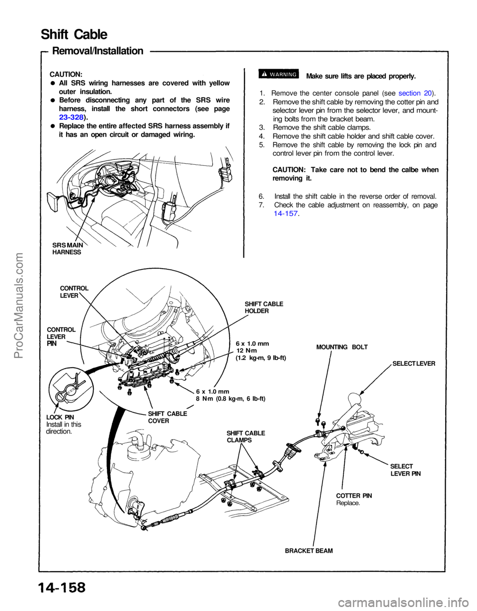
BRACKET BEAM
COTTER PIN
Replace.
SELECT
LEVER PIN SELECT LEVER
MOUNTING BOLT
SHIFT CABLE
HOLDER
6 x 1.0 mm
12 N .
m
(1.2 kg-m, 9 Ib-ft)
6 x 1.0 mm
8 N .
m (0.8 kg-m, 6 Ib-ft)
SHIFT CABLECLAMPS
SHIFT CABLE
COVER
LOCK PIN
Install in this
direction. CONTROL
LEVER
LEVER
CONTROL
SRS MAIN
HARNESS Make sure lifts are placed properly.
1. Remove the center console panel (see section 20).
2. Remove the shift cable by removing the cotter pin and
selector lever pin from the selector lever, and mount-
ing bolts from the bracket beam.
3. Remove the shift cable clamps.
4. Remove the shift cable holder and shift cable cover.
5. Remove the shift cable by removing the lock pin and
control lever pin from the control lever.
CAUTION: Take care not to bend the calbe when
removing it.
6. Install the shift cable in the reverse order of removal.
7. Check the cable adjustment on reassembly, on page
14-157.
Shift Cable
Removal/Installation
All SRS wiring harnesses are covered with yellow
outer insulation.Before disconnecting any part of the SRS wire
harness, install the short connectors (see page
23-328).
Replace the entire affected SRS harness assembly if
it has an open circuit or damaged wiring.
CAUTION:
PINProCarManuals.com
Page 1292 of 1640
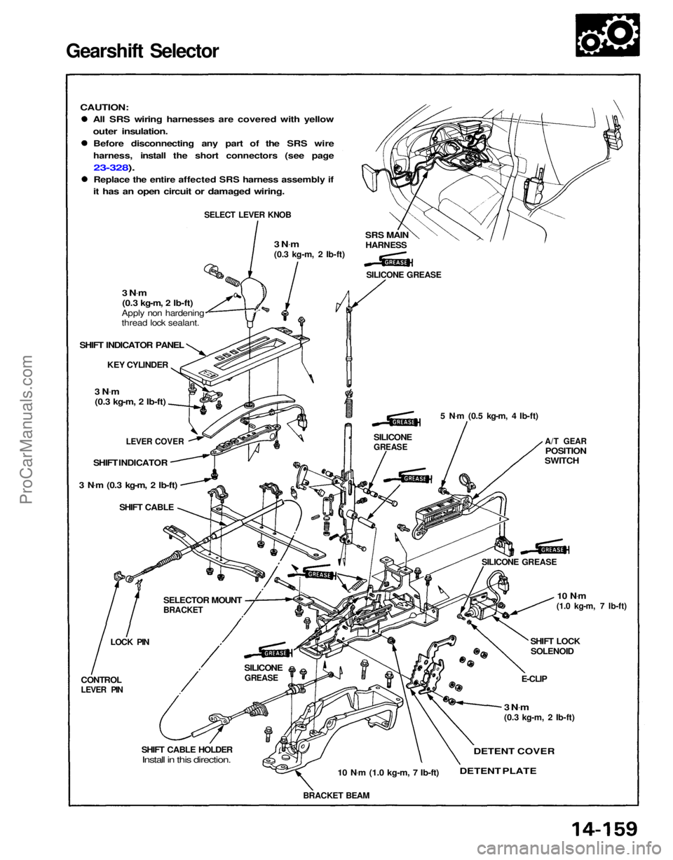
Gearshift Selector
All SRS wiring harnesses are covered with yellow
outer insulation.
Before disconnecting any part of the SRS wire
harness, install the short connectors (see page
23-328).
Replace the entire affected SRS harness assembly if
it has an open circuit or damaged wiring.
CAUTION:
SELECT LEVER KNOB
3 N.
m
(0.3 kg-m, 2 Ib-ft)
SRS MAIN
HARNESS
SILICONE GREASE
3 N .
m
(0.3 kg-m, 2 Ib-ft)
Apply non hardening
thread lock sealant.
SHIFT INDICATOR PANEL
KEY CYLINDER
3 N .
m
(0.3 kg-m, 2 Ib-ft)
5 N.
m (0.5 kg-m, 4 Ib-ft)
A/T GEAR
POSITION
SWITCH
SILICONE
GREASE
LEVER COVER
SHIFT INDICATOR
3 N .
m (0.3 kg-m, 2 Ib-ft)
SHIFT CABLE
SILICONE GREASE
10 N.
m
(1.0 kg-m, 7 Ib-ft)
SHIFT LOCK
SOLENOID
E-CLIP
3 N .
m
(0.3 kg-m, 2 Ib-ft)
DETENT COVER
DETENT
PLATE
10 N
.
m (1.0 kg-m, 7 Ib-ft)
BRACKET BEAM
SHIFT CABLE HOLDER
Install in this direction.
CONTROL
LEVER PIN
LOCK PIN
SELECTOR MOUNT
BRACKET
SILICONE
GREASEProCarManuals.com
Page 1293 of 1640
INDEX MARK
SHIFT INDICATOR
PANEL
SRS MAIN
HARNESS
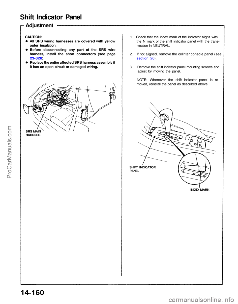
1. Check that the index mark of the indicator aligns with
the N mark of the shift indicator panel with the trans-mission in NEUTRAL.
2. If not aligned, remove the cellnter console panel (see section 20).
3. Remove the shift indicator panel mounting screws and adjust by moving the panel.
NOTE: Whenever the shift indicator panel is re-
moved, reinstall the panel as described above.
All SRS wiring harnesses are covered with yellow
outer insulation.
Before disconnecting any part of the SRS wire
harness, install the short connectors (see page
23-328).
Replace the entire affected SRS harness assembly if
it has an open circuit or damaged wiring.
CAUTION:
Adjustment
Shift Indicator PanelProCarManuals.com
Page 1294 of 1640
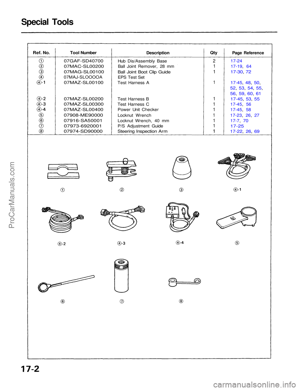
Special Tools
Ref.
No.
Tool Number
07GAF-SD40700
07MAC-SL00200
07MAG-SL00100
07MAJ-SLOOOOA
07MAZ-SL00100
07MAZ-SL00200
07MAZ-SL00300
07MAZ-SL00400
07908-ME90000
07916-SA50001
07973-6920001
07974-SD90000
Description
Hub Dis/Assembly Base Ball Joint Remover, 28 mm
Ball Joint Boot Clip Guide
EPS Test Set
Test Harness A
Test Harness B
Test Harness C Power Unit Checker
Locknut Wrench
Locknut Wrench, 40 mm
P/S Adjustment Guide
Steering Inspection Arm
Qty
2
1
1
1
1
1
1
1
1
1
1
Page Reference
17-24 17-19, 64
17-30, 72
1
7-45,
48, 50,
52, 53, 54, 55,
56, 59, 60, 61
17-45, 53, 55
17-45, 56
17-45, 58
17-23, 26, 27 17-7,
70
17-25
17-22, 26, 69ProCarManuals.com
Page 1295 of 1640
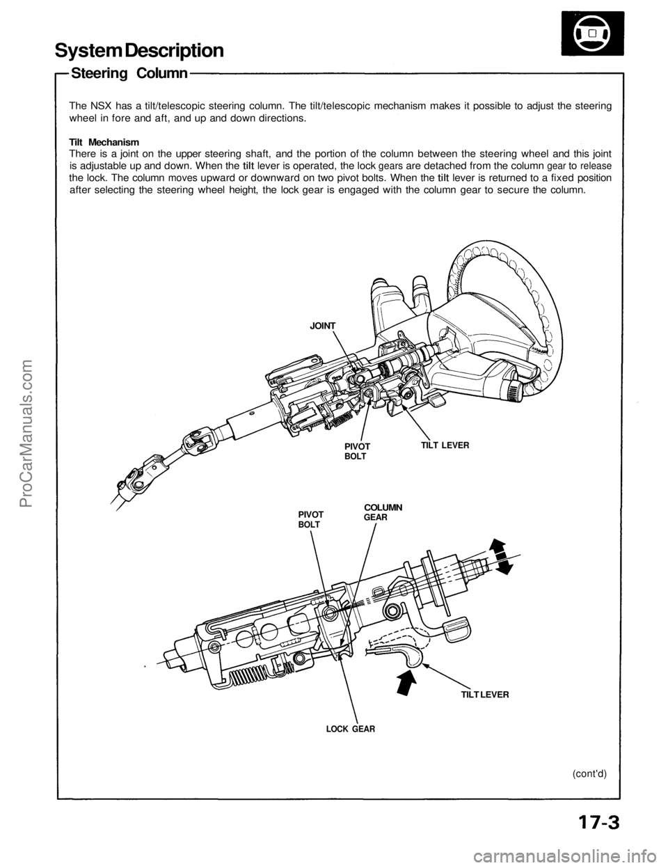
System Description
Steering Column
The NSX has a tilt/telescopic steering column. The tilt/telescopic mechanism makes it possible to adjust the steering
wheel in fore and aft, and up and down directions.
Tilt Mechanism
There is a joint on the upper steering shaft, and the portion of the column between the steering wheel and this joint
is
adjustable
up and
down. When
the
tilt
lever
is
operated,
the
lock
gears
are
detached from
the
column
gear
to
release
the
lock.
The
column
moves
upward
or
downward
on two
pivot bolts. When
the
tilt
lever
is
returned
to a
fixed position
after selecting the steering wheel height, the lock gear is engaged with the column gear to secure the column.
PIVOT
BOLT
TILT LEVER
COLUMN
GEAR
PIVOT
BOLT
LOCK GEAR
TILT LEVER
(cont'd)
JOINTProCarManuals.com
Page 1296 of 1640
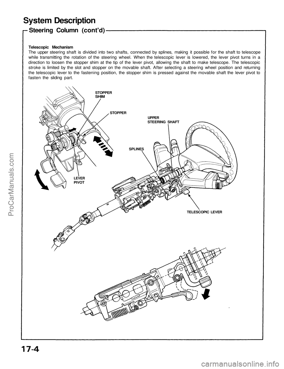
System Description
Steering Column (cont'd)
Telescopic Mechanism
The upper steering shaft is divided into two shafts, connected by splines, making it possible for the shaft to telescope
while transmitting the rotation of the steering wheel. When the telescopic lever is lowered, the lever pivot turns in a
direction to loosen the stopper shim at the tip of the lever pivot, allowing the shaft to make telescope. The telescopic
stroke is limited by the slot and stopper on the movable shaft. After selecting a steering wheel position and returning
the telescopic lever to the fastening position, the stopper shim is pressed against the movable shaft the lever pivot to
fasten the sliding part.
STOPPER
SHIM
STOPPER
UPPER
STEERING SHAFT
SPLINES
LEVER
PIVOT
TELESCOPIC LEVERProCarManuals.com
Page 1297 of 1640
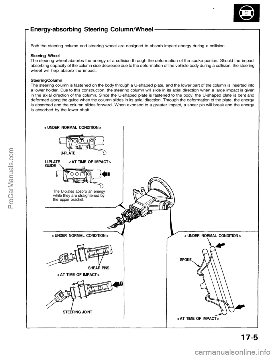
Energy-absorbing Steering Column/Wheel
Both the steering column and steering wheel are designed to absorb impact energy during a collision.
Steering Wheel
The steering wheel absorbs the energy of a collision through the deformation of the spoke portion. Should the impact
absorbing capacity of the column side decrease due to the deformation of the vehicle body during a collision, the steering
wheel will help absorb the impact.
Steering Column
The steering column is fastened on the body through a U-shaped plate, and the lower part of the column is inserted into
a lower holder. Due to this construction, the steering column will slide in its axial direction when a large impact is given
in the axial direction of the column. Since the U-shaped plate is fastened to the body, the U-shaped plate is bent and
deformed along the guide when the column slides in its axial direction. Through the deformation of the plate, the energy
is absorbed and the column slides forward. When exposed to a greater impact, a shear pin will break and the energy
is absorbed by the lower shaft.
< UNDER NORMAL CONDITION >
U-PLATE
< AT TIME OF IMPACT >
U-PLATE
GUIDE
The U-plates absorb an energy
while they are straightened by
the upper bracket.
< UNDER NORMAL CONDITION >
SHEAR PINS
< AT TIME OF IMPACT >
STEERING JOINT
< UNDER NORMAL CONDITION >
SPOKE
< AT TIME OF IMPACT >ProCarManuals.com
Page 1298 of 1640
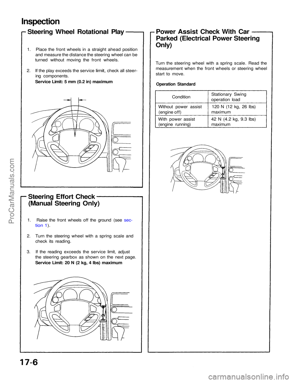
Inspection
Steering Wheel Rotational Play
1. Place the front wheels in a straight ahead position and measure the distance the steering wheel can be
turned without moving the front wheels.
2. If the
play
exceeds
the
service
limit,
check
all
steer- ing components.
Service Limit: 5 mm (0.2 in) maximum
Steering Effort Check (Manual Steering Only)
Operation Standard
Turn the steering wheel with a spring scale. Read the
measurement when the front wheels or steering wheel
start to move.Power Assist Check With Car
Parked (Electrical Power Steering
Only)
1. Raise the front wheels off the ground (see sec-
tion 1).
2. Turn the steering wheel with a spring scale and check its reading.
3. If the reading exceeds the service limit, adjust the steering gearbox as shown on the next page.
Service Limit: 20 N (2 kg, 4 Ibs) maximum Condition
Without power assist (engine off)
With power assist (engine running) Stationary Swing
operation load
120 N (12 kg, 26
Ibs)
maximum
42 N
(4.2
kg, 9.3
Ibs) maximumProCarManuals.com
Page 1299 of 1640
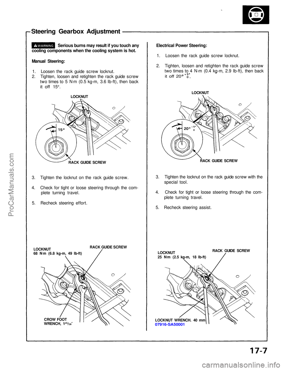
Steering Gearbox Adjustment
Serious burns may result if you touch any
cooling components when the cooling system is hot.
Manual Steering:
1. Loosen the rack guide screw locknut.
2. Tighten, loosen and retighten the rack guide screw
two times to 5 N .
m (0.5 kg-m, 3.6 Ib-ft), then back
it off
15°.
RACK GUIDE SCREW
3. Tighten the locknut on the rack guide screw.
4. Check for tight or loose steering through the com- plete turning travel.
5. Recheck steering effort.
RACK GUIDE SCREW
LOCKNUT
68 N ·
m (6.8 kg-m, 49 Ib-ft)
CROW FOOT LOCKNUT
Electrical Power Steering:
1. Loosen the rack guide screw locknut.
2. Tighten, loosen and retighten the rack guide screw two times to 4 N·m (0.4 kg-m, 2.9 Ib-ft), then back
LOCKNUT
RACK GUIDE SCREW
3. Tighten the locknut on the rack guide screw with the special tool.
4. Check for tight or loose steering through the com- plete turning travel.
5. Recheck steering assist.
LOCKNUT
25 N .
m (2.5 kg-m, 18 Ib-ft) RACK GUIDE SCREW
LOCKNUT WRENCH. 40 mm
07916-SA50001
it off 20
WRENCH,ProCarManuals.com
Page 1300 of 1640
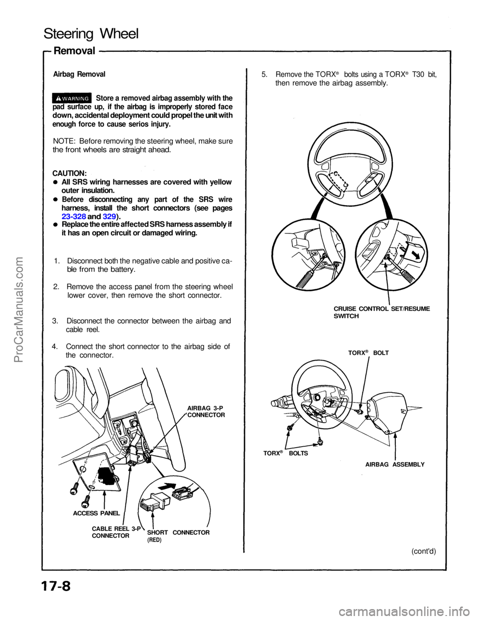
Steering Wheel
Removal
Airbag Removal
Store a removed airbag assembly with the
pad surface up, if the airbag is improperly stored face
down, accidental deployment could propel the unit with
enough force to cause serios injury.
NOTE: Before removing the steering wheel, make sure
the front wheels are straight ahead.
CAUTION:
All SRS wiring harnesses are covered with yellow
outer insulation.
Before disconnecting any part of the SRS wire
harness, install the short connectors (see pages
23-328 and 329).
Replace the entire affected SRS harness assembly if
it has an open circuit or damaged wiring.
1. Disconnect both the negative cable and positive ca-
ble from the battery.
2. Remove the access panel from the steering wheel lower cover, then remove the short connector.
3. Disconnect the connector between the airbag and cable reel.
4. Connect the short connector to the airbag side of the connector.
AIRBAG 3-PCONNECTOR
SHORT CONNECTOR
(RED)
CABLE REEL 3-P
CONNECTOR
ACCESS PANEL
CRUISE CONTROL SET/RESUME
SWITCH
TORX ®
BOLT
AIRBAG ASSEMBLY (cont'd)
5. Remove the TORX
®
bolts using a TORX ®
T30 bit,
then remove the airbag assembly.
TORX ®
BOLTSProCarManuals.com