ACURA NSX 1991 Service Repair Manual
Manufacturer: ACURA, Model Year: 1991,
Model line: NSX,
Model: ACURA NSX 1991
Pages: 1640, PDF Size: 60.48 MB
ACURA NSX 1991 Service Repair Manual
NSX 1991
ACURA
ACURA
https://www.carmanualsonline.info/img/32/56988/w960_56988-0.png
ACURA NSX 1991 Service Repair Manual
Trending: open hood, dimensions, ESP, wheel bolts, electrical wiring, clock setting, lug pattern
Page 1601 of 1640
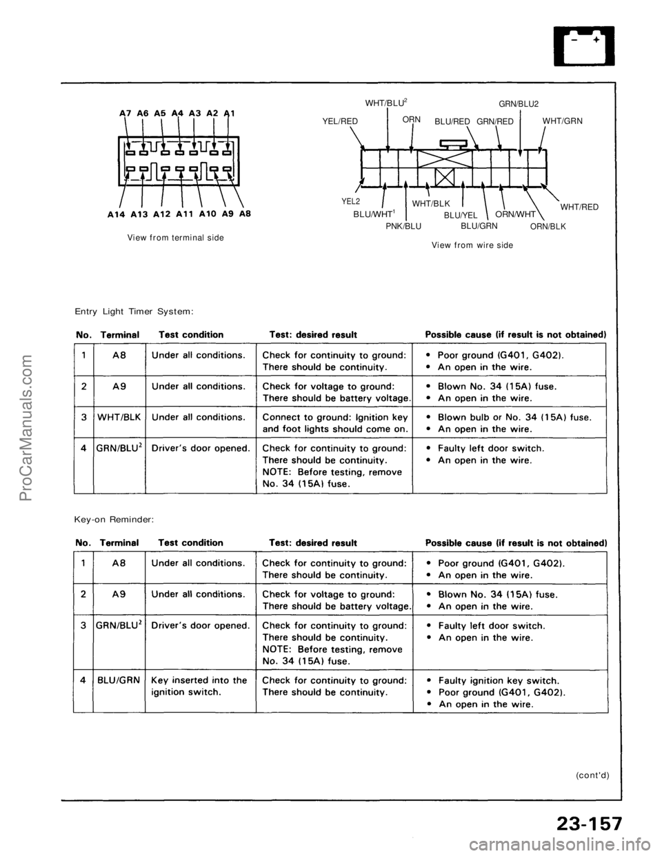
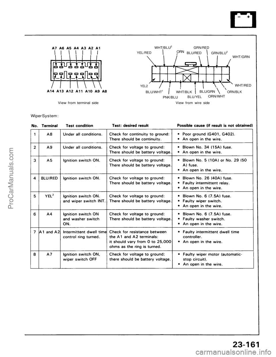
YEL/RED
WHT/BLU2
ORN
BLU/RED
GRN/RED
GRN/BLU2
WHT/GRN
YEL2
BLU/WHT1
WHT/BLK
BLU/YEL
BLU/GRN
ORN/WHT
ORN/BLK
WHT/RED
View from wire side
PNK/BLU
View from terminal side
Entry Light Timer System:
Key-on Reminder:
(cont'd)ProCarManuals.com
Page 1602 of 1640
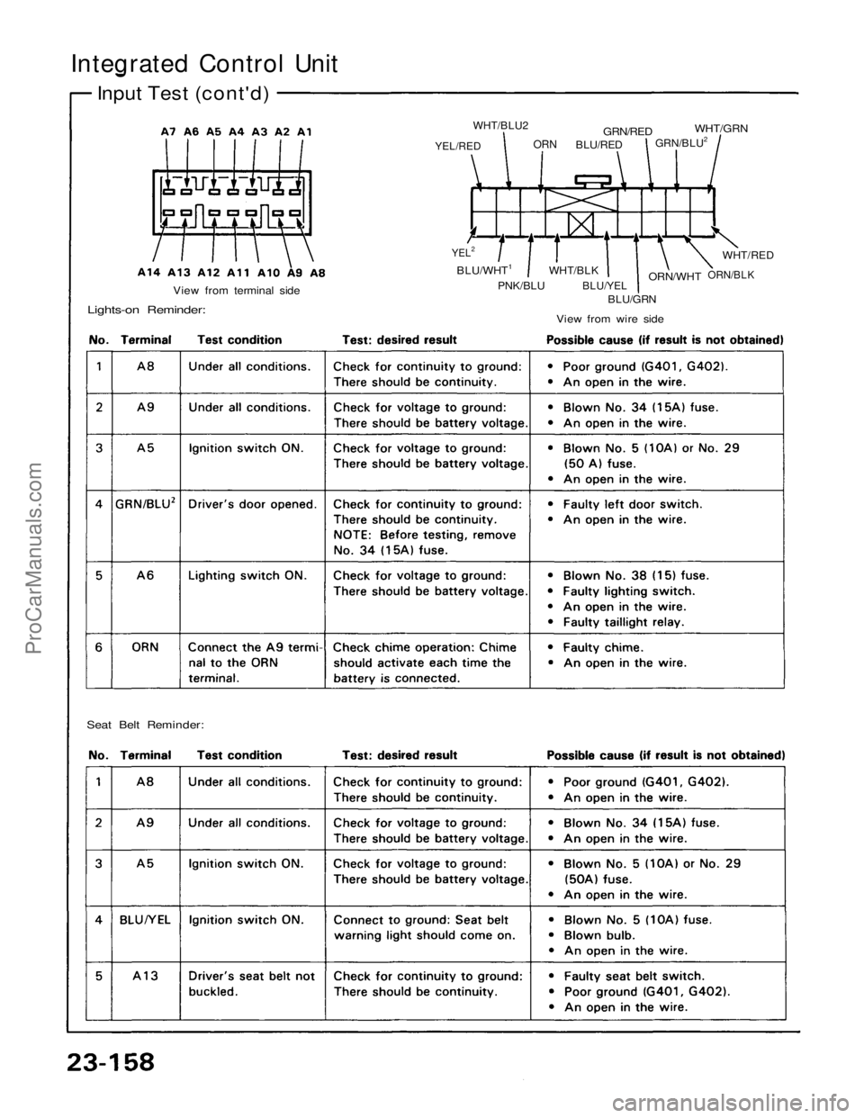
Integrated Control Unit
Input Test (cont'd)
YEL/RED
WHT/BLU2
ORN
BLU/RED
GRN/RED
GRN/BLU2
WHT/GRN
YEL2
BLU/WHT1
PNK/BLU
WHT/BLK
BLU/YEL
BLU/GRN
ORN/WHT
ORN/BLK
WHT/RED
View from wire side
View from terminal side
Lights-on Reminder:
Seat Belt Reminder:ProCarManuals.com
Page 1603 of 1640
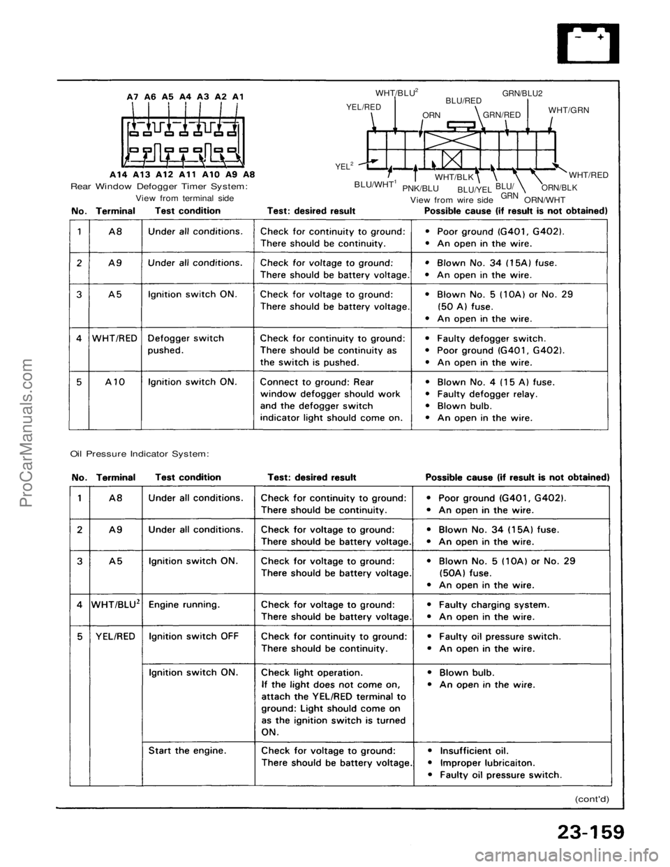
Rear Window Defogger Timer System:
View from terminal side
YEL/RED
WHT/BLU2
ORN
BLU/RED
GRN/RED
GRN/BLU2
WHT/GRN
YEL2
BLU/WHT1
PNK/BLU
WHT/BLK
BLU/YEL
BLU/
GRN
ORN/WHT
ORN/BLK
WHT/RED
View from wire side
Oil Pressure Indicator System:
(cont'd)ProCarManuals.com
Page 1604 of 1640
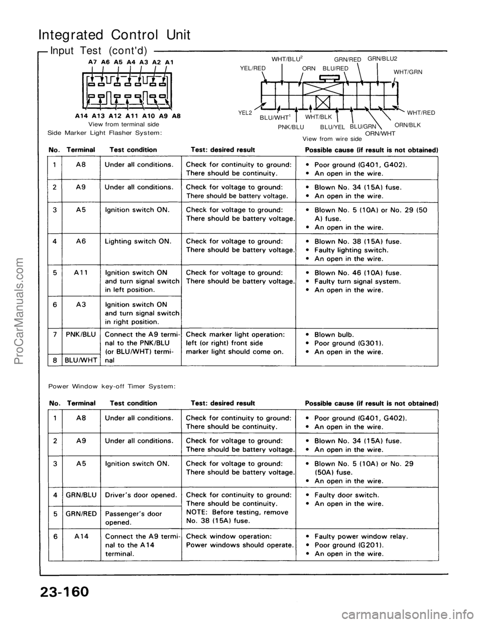
Integrated Control Unit
Input Test (cont'd)
View from terminal side
Side Marker Light Flasher System:
YEL/RED
WHT/BLU2
ORN
BLU/RED
GRN/RED
GRN/BLU2
WHT/GRN
YEL2
BLU/WHT1
PNK/BLU
WHT/BLK
BLU/YEL
BLU/GRN
ORN/WHT
ORN/BLK
WHT/RED
View from wire side
Power Window key-off Timer System:ProCarManuals.com
Page 1605 of 1640
YEL/RED
WHT/BLU2
ORN
BLU/RED
GRN/RED
GRN/BLU2
WHT/GRN
YEL2
BLU/WHT1
PNK/BLU
WHT/BLK
BLU/YEL
BLU/GRN
ORN/WHT
ORN/BLK
WHT/RED
View from wire side
View from terminal side
Wiper System:ProCarManuals.com
Page 1606 of 1640
Lighting System
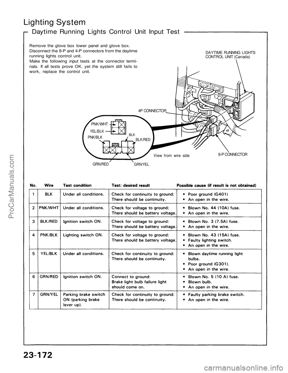
Daytime Running Lights Control Unit Input Test
Remove the glove box lower panel and glove box.
Disconnect the 8-P and 4-P connectors from the daytime
running lights control unit.
Make the following input tests at the connector termi-
nals. If all tests prove OK, yet the system still fails to
work, replace the control unit.
4P CONNECTOR
PNK/WHT
YEL/BLK
PNK/BLK
BLK
BLK/RED
GRN/RED
GRN/YEL
View from wire side
8-P CONNECTOR
DAYTIME RUNNING LIGHTS
CONTROL UNIT (Canada)ProCarManuals.com
Page 1607 of 1640
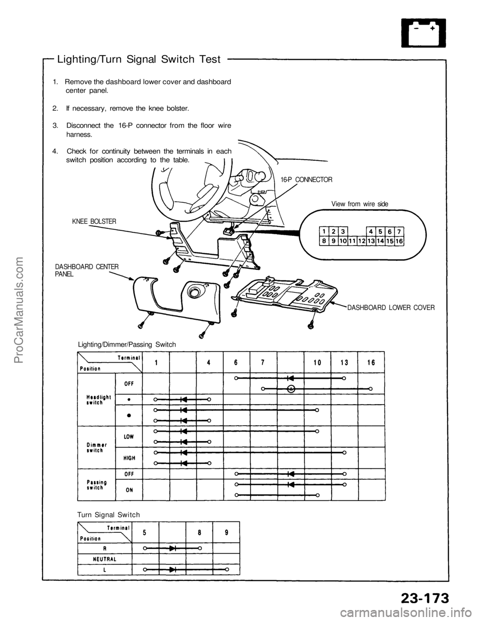
Lighting/Turn Signal Switch Test
1. Remove the dashboard lower cover and dashboard center panel.
2. If necessary, remove the knee bolster. 3. Disconnect the 16-P connector from the floor wire
harness.
4. Check for continuity between the terminals in each switch position according to the table.
KNEE BOLSTER
DASHBOARD CENTER
PANEL
Lighting/Dimmer/Passing Switch
Turn Signal Switch
DASHBOARD LOWER COVER
View from wire side
16-P CONNECTORProCarManuals.com
Page 1608 of 1640
Lighting System
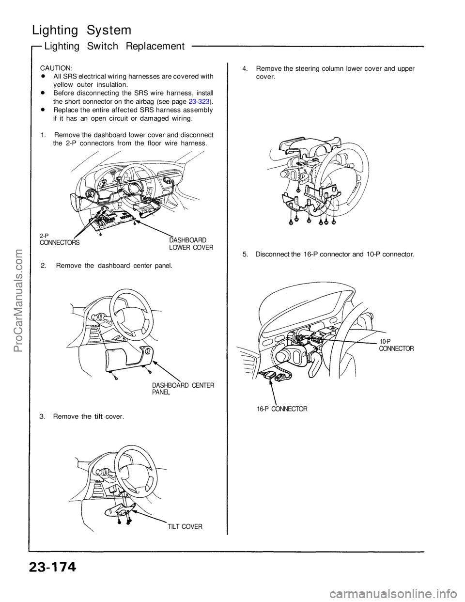
Lighting Switch Replacement
CAUTION: All SRS electrical wiring harnesses are covered with
yellow outer insulation.
Before disconnecting the SRS wire harness, install
the short connector on the airbag (see page 23-323). Replace the entire affected SRS harness assembly
if it has an open circuit or damaged wiring.
1. Remove the dashboard lower cover and disconnect the 2-P connectors from the floor wire harness.
2-P
CONNECTORS
DASHBOARD
LOWER COVER
2. Remove the dashboard center panel.
DASHBOARD CENTER
PANEL
3.
Remove
the
tilt
cover.
TILT COVER
4. Remove the steering column lower cover and upper
cover.
5. Disconnect the 16-P connector and 10-P connector.
10-P
CONNECTOR
16-P CONNECTORProCarManuals.com
Page 1609 of 1640
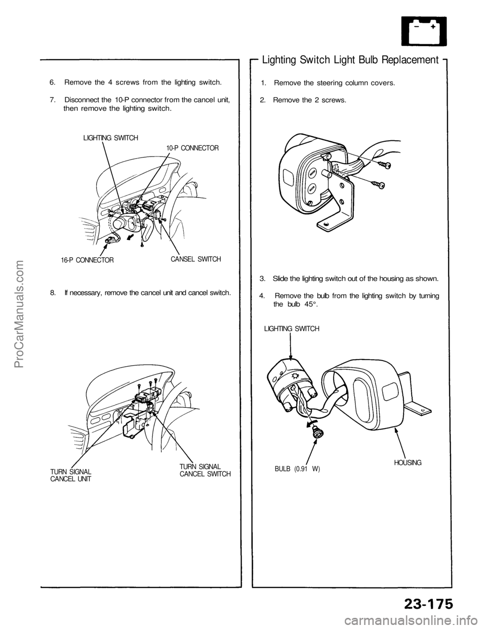
6. Remove the 4 screws from the lighting switch.
7. Disconnect the 10-P connector from the cancel unit,
then remove the lighting switch.
Lighting Switch Light Bulb Replacement
1. Remove the steering column covers.
2. Remove the 2 screws.
3. Slide the lighting switch out of the housing as shown.
4. Remove the bulb from the lighting switch by turning
the bulb 45°.
BULB (0.91 W)
HOUSING
LIGHTING SWITCH
10-P CONNECTOR
16-P CONNECTOR
CANSEL SWITCH
8. If necessary, remove the cancel unit and cancel switch.
TURN SIGNAL
CANCEL UNIT
TURN SIGNAL
CANCEL SWITCH
LIGHTING SWITCHProCarManuals.com
Page 1610 of 1640
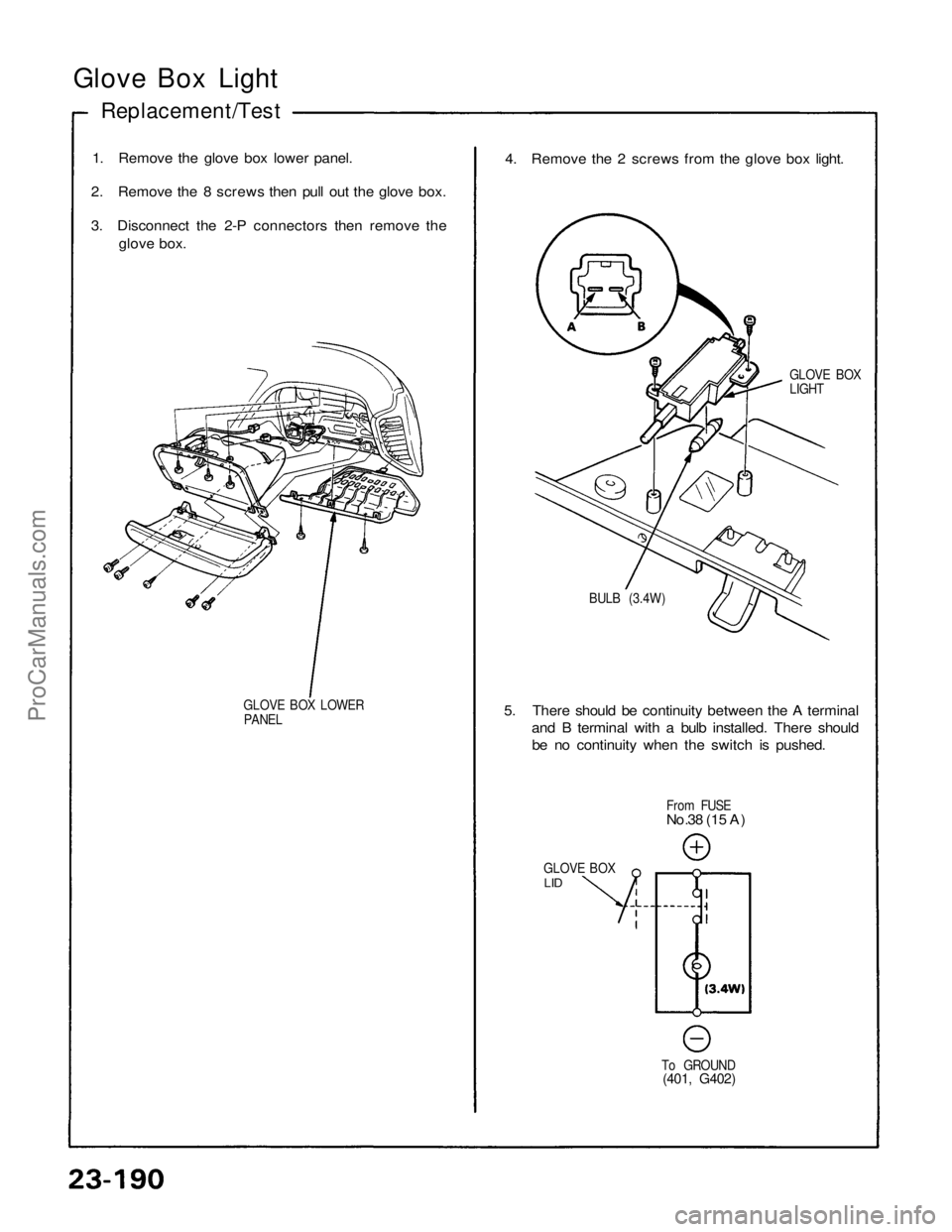
Glove Box Light
Replacement/Test
1. Remove the glove box lower panel.
2. Remove the 8 screws then pull out the glove box.
3. Disconnect the 2-P connectors then remove the
glove box.
GLOVE BOX LOWER
PANEL
4. Remove the 2 screws from the glove box light.
GLOVE BOX
LIGHT
BULB (3.4W)
5. There should be continuity between the A terminal
and B terminal with a bulb installed. There should
be no continuity when the switch is pushed.
From FUSE
No.38 (15 A)
GLOVE BOX
LID
To GROUND
(401, G402)ProCarManuals.com
Trending: buttons, CD changer, spark plugs, tire type, towing, suspension, clock reset
