ACURA NSX 1991 Service Repair Manual
Manufacturer: ACURA, Model Year: 1991, Model line: NSX, Model: ACURA NSX 1991Pages: 1640, PDF Size: 60.48 MB
Page 1581 of 1640
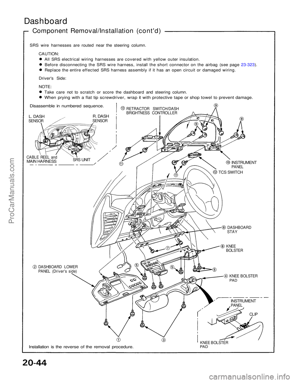
Dashboard
Component Removal/Installation (cont'd)
SRS wire harnesses are routed near the steering column. CAUTION: All SRS electrical wiring harnesses are covered with yellow outer insulation.
Before disconnecting the SRS wire harness, install the short connector on the airbag (see page 23-323).
Replace the entire effected SRS harness assembly if it has an open circuit or damaged wiring.
Driver's Side:
NOTE: Take care not to scratch or score the dashboard and steering column.
When prying with a flat tip screwdriver, wrap it with protective tape or shop towel to prevent damage.
Disassemble in numbered sequence.
L. DASH
SENSOR
R. DASH
SENSOR
CABLE REEL and
MAIN HARNESS
SRS
UNIT
RETRACTOR SWITCH/DASH
BRIGHTNESS CONTROLLER
INSTRUMENT
PANEL
TCS SWITCH
DASHBOARD
STAY
KNEE
BOLSTER
DASHBOARD LOWER
PANEL (Driver's side) KNEE BOLSTER
PAD
INSTRUMENT
PANEL
CLIP
KNEE BOLSTER
PAD
Installation is the reverse of the removal procedure.ProCarManuals.com
Page 1582 of 1640
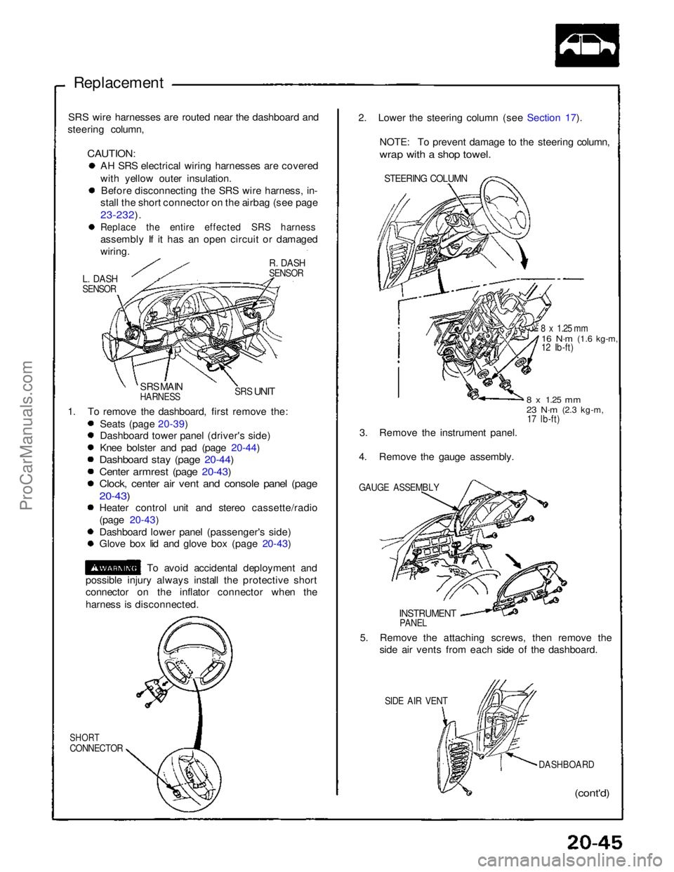
Replacement
SRS wire harnesses are routed near the dashboard and
steering column,
CAUTION:
AH SRS electrical wiring harnesses are covered
with yellow outer insulation.
Before disconnecting the SRS wire harness, in-
stall the short connector on the airbag (see page
23-232).
Replace the entire effected SRS harness
assembly If it has an open circuit or damaged
wiring.
R. DASH
SENSOR
L. DASH
SENSOR
SRS MAIN
HARNESS
SRS
UNIT
1. To remove the dashboard, first remove the: Seats (page 20-39)
Dashboard tower panel (driver's side)
Knee bolster and pad (page 20-44)
Dashboard stay (page 20-44)
Center armrest (page 20-43)
Clock, center air vent and console panel (page
20-43)
Heater control unit and stereo cassette/radio
(page 20-43)
Dashboard lower panel (passenger's side)
Glove box lid and glove box (page 20-43)
To avoid accidental deployment and
possible injury always install the protective short
connector on the inflator connector when the
harness is disconnected.
SHORT
CONNECTOR
(cont'd)
DASHBOARD
SIDE AIR VENT
5. Remove the attaching screws, then remove the
side air vents from each side of the dashboard.
INSTRUMENT
PANEL
GAUGE ASSEMBLY
3. Remove the instrument panel.
4. Remove the gauge assembly.
8 x
1.25
mm
23 N·m
(2.3 kg-m,
17 lb-ft)
8 x 1.25 mm
16 N·m
(1.6 kg-m,
12 Ib-ft)
STEERING COLUMN
2. Lower the steering column (see Section 17).
NOTE: To prevent damage to the steering column,
wrap with a shop towel.ProCarManuals.com
Page 1583 of 1640
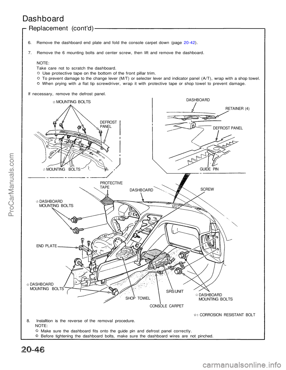
6. Remove the dashboard end plate and fold the console carpet down (page 20-42).
7. Remove the 6 mounting bolts and center screw, then lift and remove the dashboard.
NOTE:
Take care not to scratch the dashboard.
Use protective tape on the bottom of the front pillar trim.
To prevent damage to the change lever (M/T) or selecter lever and indicator panel (A/T), wrap with a shop towel. When prying with a flat tip screwdriver, wrap it with protective tape or shop towel to prevent damage.
If necessary, remove the defrost panel.
MOUNTING BOLTS
DASHBOARD
RETAINER (4)
DASHBOARD
MOUNTING BOLTS
END PLATE
DASHBOARD
MOUNTING BOLTS CONSOLE CARPETDASHBOARD
MOUNTING BOLTS
CORROSION RESISTANT BOLT
8. Installtion is the reverse of the removal procedure.
NOTE:
Make sure the dashboard fits onto the guide pin and defrost panel correctly. Before tightening the dashboard bolts, make sure the dashboard wires are not pinched.
Dashboard
Replacement (cont'd)
DEFROST PANEL
PROTECTIVE
TAPE SCREW
DASHBOARD
SHOP TOWEL GUIDE PIN
DEFROST
PANEL
MOUNTING BOLTS
SRS UNITProCarManuals.com
Page 1584 of 1640
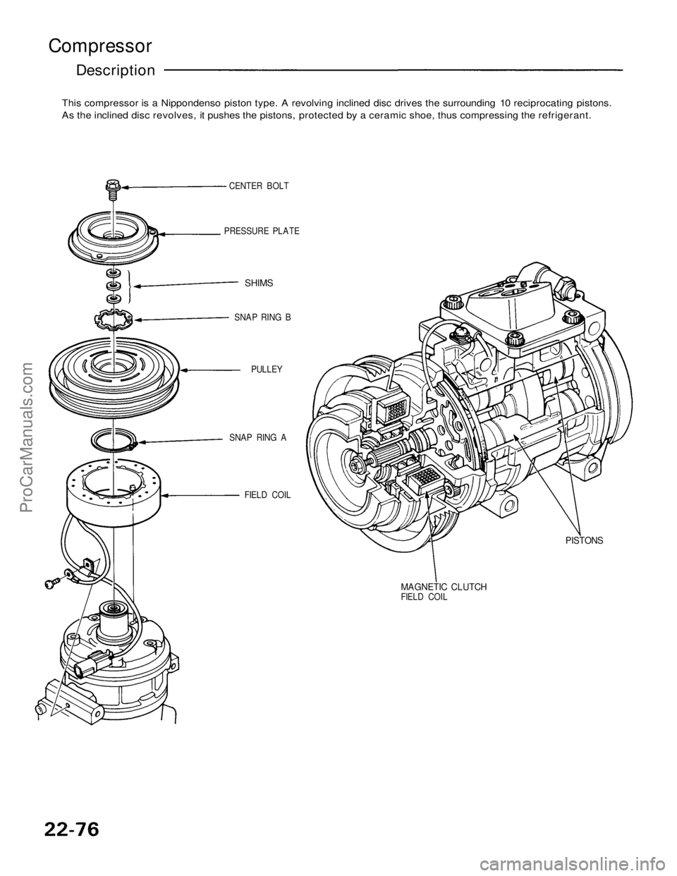
Compressor
Description
This compressor is a Nippondenso piston type. A revolving inclined disc drives the surrounding 10 reciprocating pistons.
As the inclined disc revolves, it pushes the pistons, protected by a ceramic shoe, thus compressing the refrigerant.
CENTER BOLT
PRESSURE PLATE
SHIMS
SNAP RING B
PULLEY
SNAP RING A
FIELD COIL
MAGNETIC CLUTCH
FIELD COIL
PISTONSProCarManuals.com
Page 1585 of 1640
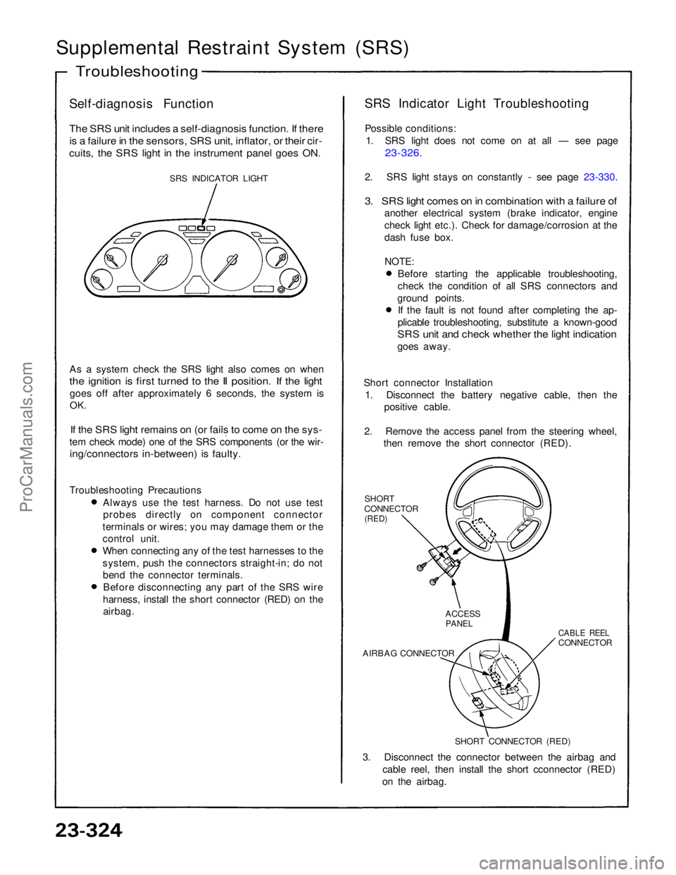
Supplemental Restraint System (SRS)
Self-diagnosis Function
The SRS unit includes a self-diagnosis function. If there
is a failure in the sensors, SRS unit, inflator, or their cir-
cuits, the SRS light in the instrument panel goes ON.
SRS INDICATOR LIGHT
As a system check the SRS light also comes on when
the ignition is first turned to the II position. If the light
goes off after approximately 6 seconds, the system is
OK.
If the SRS light remains on (or fails to come on the sys-
tem check mode) one of the SRS components (or the wir-
ing/connectors in-between) is faulty.
Troubleshooting Precautions Always use the test harness. Do not use test
probes directly on component connector
terminals or wires; you may damage them or the
control unit. When connecting any of the test harnesses to the
system, push the connectors straight-in; do not
bend the connector terminals. Before disconnecting any part of the SRS wire
harness, install the short connector (RED) on the airbag. SRS Indicator Light Troubleshooting
Possible conditions: 1. SRS light does not come on at all — see page
23-326.
2. SRS light stays on constantly - see page 23-330.
3. SRS light comes on in combination with a failure of
another electrical system (brake indicator, engine
check light etc.). Check for damage/corrosion at the
dash fuse box.
NOTE:
Before starting the applicable troubleshooting,
check the condition of all SRS connectors and
ground points. If the fault is not found after completing the ap-
plicable troubleshooting, substitute a known-good
SRS unit and check whether the light indication
goes away.
Short connector Installation 1. Disconnect the battery negative cable, then the positive cable.
2. Remove the access panel from the steering wheel, then remove the short connector (RED).
SHORT
CONNECTOR
(RED)
3. Disconnect the connector between the airbag and cable reel, then install the short cconnector (RED)
on the airbag.
Troubleshooting
SHORT CONNECTOR (RED)
AIRBAG CONNECTOR
CABLE REEL
CONNECTOR
ACCESS
PANELProCarManuals.com
Page 1586 of 1640
Under-Dash Fuse Box
Removal/Installation
CAUTION;
Be sure to install the SRS wiring so that it is not
pinched or interfering with other car parts.
Always keep the short connector on the airbag con-
nector when the harness is disconnected.
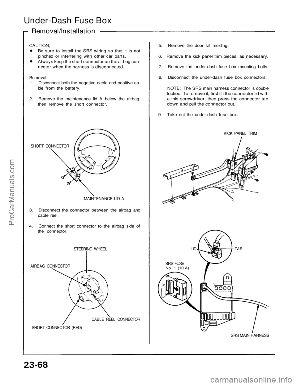
Removal:
1. Disconnect both the negative cable and positive ca-
ble from the battery.
2. Remove the maintenance lid A below the airbag,
then remove the short connector.
SHORT CONNECTOR
MAINTENANCE LID A
3. Disconnect the connector between the airbag and
cable reel.
4. Connect the short connector to the airbag side of
the connector.
STEERING WHEEL
AIRBAG CONNECTOR
CABLE REEL CONNECTOR
SHORT CONNECTOR (RED)
5. Remove the door sill molding.
6. Remove the kick panel trim pieces, as necessary.
7. Remove the under-dash fuse box mounting bolts.
8. Disconnect the under-dash fuse box connectors.
NOTE: The SRS main harness connector is double
locked. To remove it, first lift the connector lid with
a thin screwdriver, then press the connector tab
down and pull the connector out.
9. Take out the under-dash fuse box.
TAB
SRS FUSE
No. 1 (10 A)
SRS MAIN HARNESS
KICK PANEL TRIM
LIDProCarManuals.com
Page 1587 of 1640
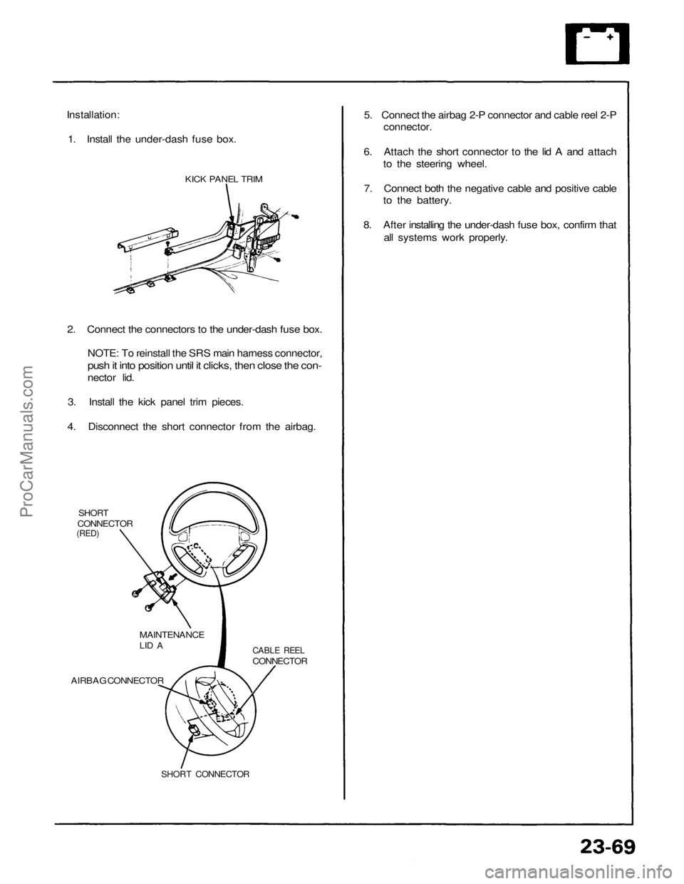
Installation:
1. Install the under-dash fuse box.
KICK PANEL TRIM
2. Connect the connectors to the under-dash fuse box.
NOTE: To reinstall the SRS main harness connector,
push it into position until it clicks, then close the con-
nector lid.
3. Install the kick panel trim pieces.
4. Disconnect the short connector from the airbag.
SHORT
CONNECTOR
(RED)
MAINTENANCE
LID A
CABLE REEL
CONNECTOR
AIRBAG CONNECTOR
SHORT CONNECTOR
5. Connect the airbag 2-P connector and cable reel 2-P
connector.
6. Attach the short connector to the lid A and attach
to the steering wheel.
7. Connect both the negative cable and positive cable
to the battery.
8. After installing the under-dash fuse box, confirm that
all systems work properly.ProCarManuals.com
Page 1588 of 1640
Steering Lock Replacement
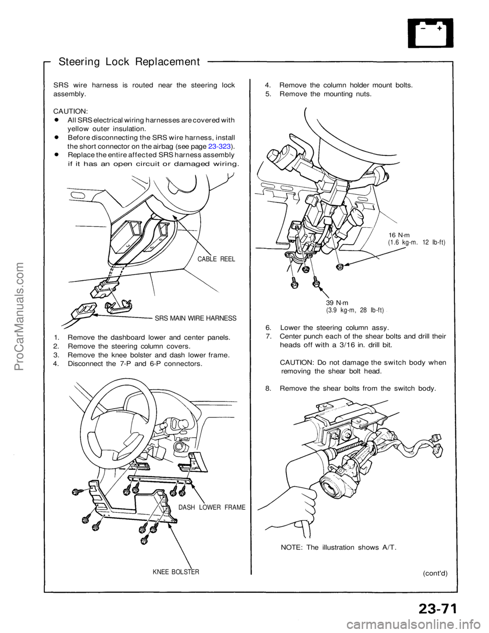
SRS wire harness is routed near the steering lock
assembly.
CAUTION:
All SRS electrical wiring harnesses are covered with
yellow outer insulation.Before disconnecting the SRS wire harness, install
the short connector on the airbag (see page 23-323). Replace the entire affected SRS harness assembly
if it has an open circuit or damaged wiring.
CABLE REEL
SRS MAIN WIRE HARNESS
1. Remove the dashboard lower and center panels.
2. Remove the steering column covers. 3. Remove the knee bolster and dash lower frame.
4. Disconnect the 7-P and 6-P connectors.
DASH LOWER FRAME
KNEE BOLSTER
(cont'd)
NOTE: The illustration shows A/T.
6. Lower the steering column assy.
7. Center punch each of the shear bolts and drill their
heads off with a 3/16 in. drill bit.
CAUTION: Do not damage the switch body when
removing the shear bolt head.
8. Remove the shear bolts from the switch body.
39 N·m
(3.9 kg-m, 28 Ib-ft)
16 N·m
(1.6 kg-m. 12 Ib-ft)
4. Remove the column holder mount bolts.
5. Remove the mounting nuts.ProCarManuals.com
Page 1589 of 1640
Ignition Switch
Steering Lock Replacement (cont'd)
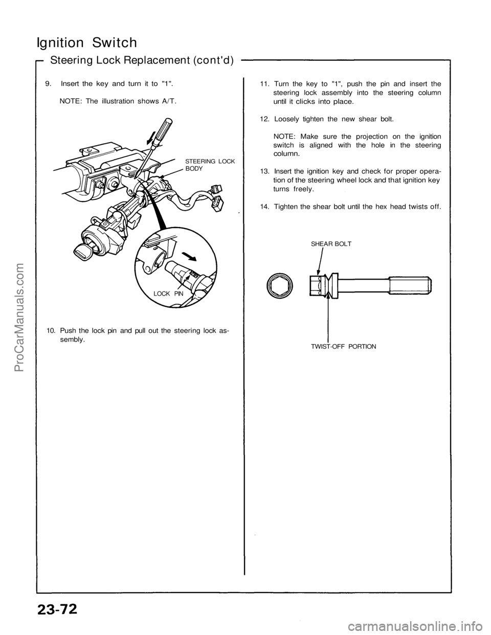
9. Insert the key and turn it to "1".
NOTE: The illustration shows A/T.
STEERING LOCK
BODY
LOCK PIN
10. Push the lock pin and pull out the steering lock as-
sembly.
TWIST-OFF PORTION
SHEAR BOLT
11. Turn the key to "1", push the pin and insert the
steering lock assembly into the steering column
until it clicks into place.
12. Loosely tighten the new shear bolt.
NOTE: Make sure the projection on the ignition
switch is aligned with the hole in the steering
column.
13. Insert the ignition key and check for proper opera-
tion of the steering wheel lock and that ignition key
turns freely.
14. Tighten the shear bolt until the hex head twists off.ProCarManuals.com
Page 1590 of 1640
Radiator and Condenser Fan Controls
Description
Fan control system:
The cooling fan system is comprised of radiator fan, condenser fan (left, right), engine compartment fan, radiator fan
low relay, radiator fan high relay, condenser fan relay, engine room fan relay, radiator fan resistor, coolant temperature
sensor, A/C pressure switch, cooling fan control unit, climate control unit, and PGM-FI ECU.
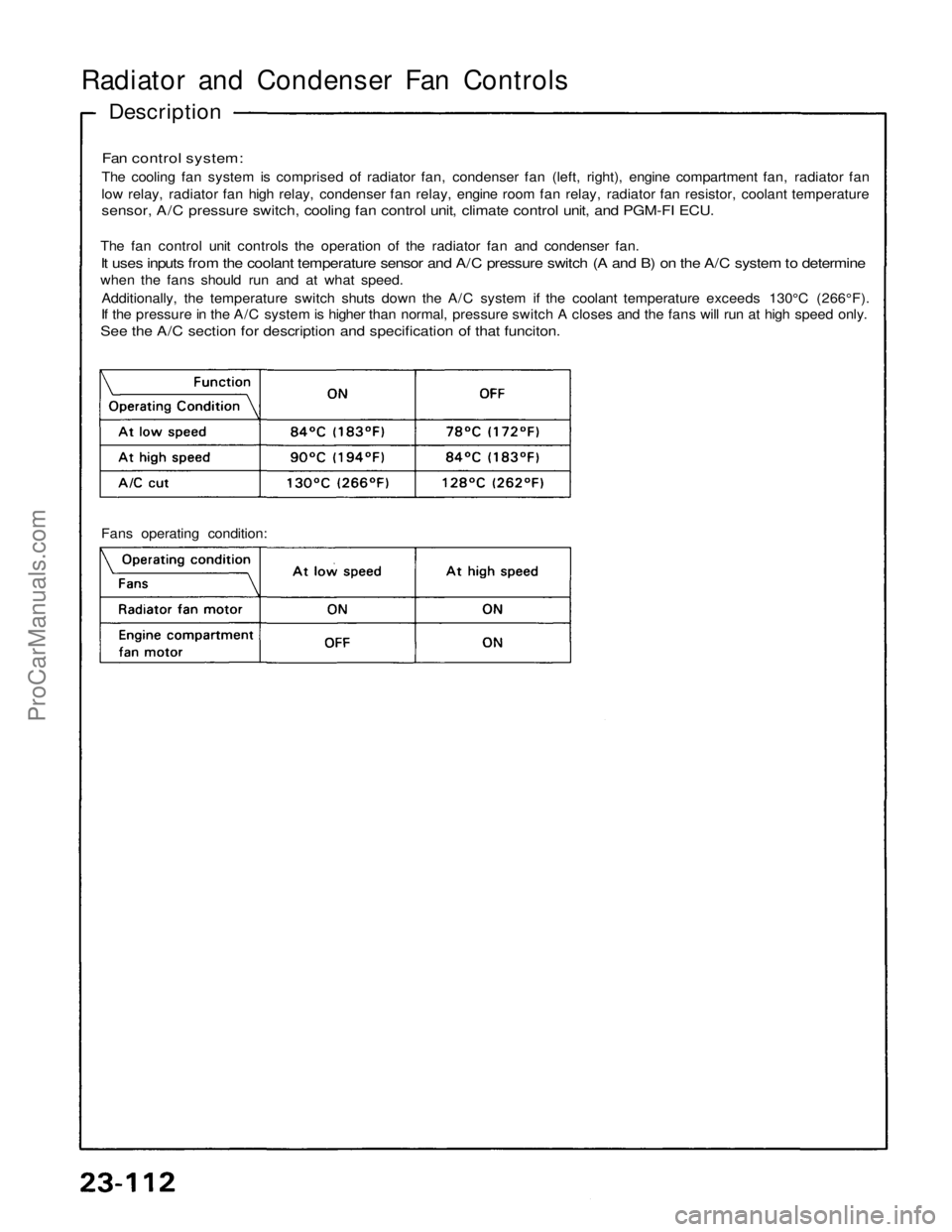
The fan control unit controls the operation of the radiator fan and condenser fan.
It uses inputs from the coolant temperature sensor and A/C pressure switch (A and B) on the A/C system to determine
when the fans should run and at what speed.
Additionally, the temperature switch shuts down the A/C system if the coolant temperature exceeds 130°C (266°F).
If the pressure in the A/C system is higher than normal, pressure switch A closes and the fans will run at high speed only.
See the A/C section for description and specification of that funciton.
Fans operating condition:ProCarManuals.com