ACURA NSX 1991 Service Repair Manual
Manufacturer: ACURA, Model Year: 1991,
Model line: NSX,
Model: ACURA NSX 1991
Pages: 1640, PDF Size: 60.48 MB
ACURA NSX 1991 Service Repair Manual
NSX 1991
ACURA
ACURA
https://www.carmanualsonline.info/img/32/56988/w960_56988-0.png
ACURA NSX 1991 Service Repair Manual
Trending: steering wheel, headlights, warning lights, stop start, wheel bolt torque, heating, fuse box location
Page 1591 of 1640
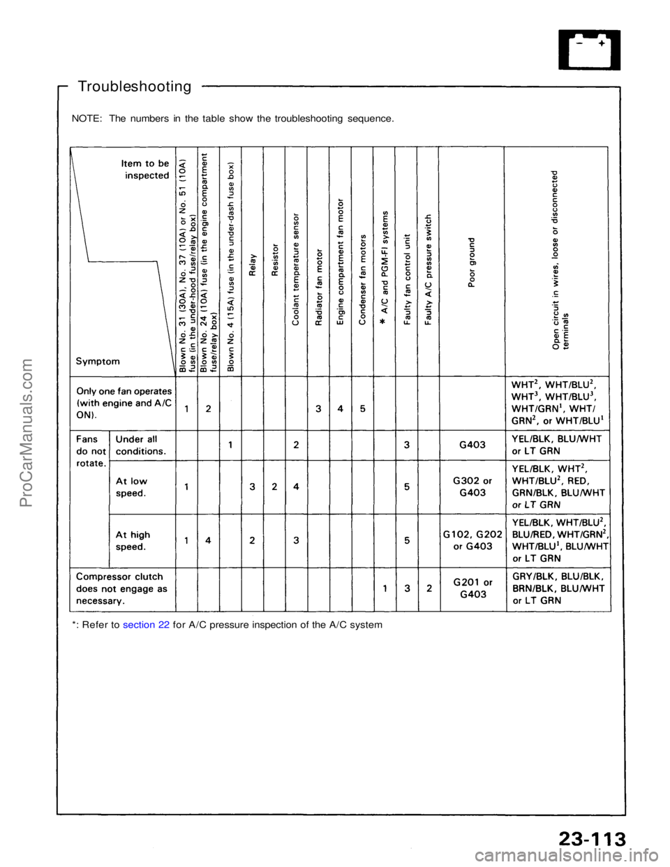
Troubleshooting
NOTE: The numbers in the table show the troubleshooting sequence.
*: Refer to section 22 for A/C pressure inspection of the A/C systemProCarManuals.com
Page 1592 of 1640
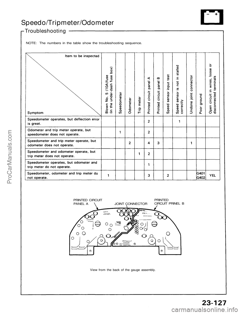
Speedo/Tripmeter/Odometer
Troubleshooting
NOTE: The numbers in the table show the troubleshooting sequence.
PRINTED CIRCUITPANEL A
JOINT CONNECTOR PRINTED
CIRCUIT PRINEL B
View from the back of the gauge assembly.ProCarManuals.com
Page 1593 of 1640
— Defective gauge assemble, check for the A21
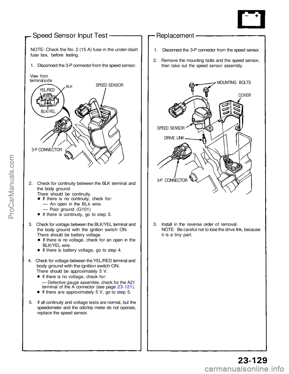
Speed Sensor Input Test
NOTE
:
Check the No. 2 (15 A) fuse in the under-dash
fuse box, before testing.
1. Disconnect the 3-P connector from the speed sensor.
View from
terminal side
SPEED SENSOR
3-P CONNECTOR
2. Check for continuity between the BLK terminal and the body ground.
There should be continuity. If there is no continuity, check for:
— An open in the BLk wire.
— Poor ground (G101) If there is continuity, go to step 3.
3. Check for vortage between the BLK/YEL terminal and the body ground with the ignition switch ON.
There should be battery voltage. If there is no voltage, check for an open in the
BLK/YEL wire. If there is battery voltage, go to step 4.
4. Check for voltage between the YEL/RED terminal and
bod
y
ground with the ignition switch ON.
There should be approximately 5 V.
If there is no voltage, check for:
terminal of the A connector (see page 23-121). If there are approximately 5 V, go to step 5.
5. If all continuity and voltage tests are normal, but the speedometer and the odo/trip meter do not operate,
replace the speed sensor.
Replacement
1. Disconnect the 3-P connector from the speed sensor.
2. Remove the mounting bolts and the speed sensor,
then take out the speed sensor assembly.
DRIVE LINK
3-P CONNECTOR
3. Install in the reverse order of removal. NOTE: Be careful not to lose the drive link, because
it is a tiny part.
BLK
YEL/RED
BLK/YEL
SPEED SENSOR
COVER
MOUNTING BOLTSProCarManuals.com
Page 1594 of 1640
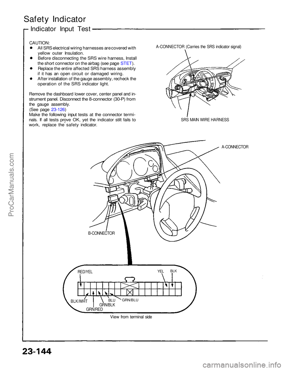
CAUTION:
All SRS electrical wiring harnesses are covered with
yellow outer Insulation. Before disconnecting the SRS wire harness, Install
the short connector on the airbag (see page STET). Replace the entire affected SRS harness assembly
if it has an open circuit or damaged wiring. After installation of the gauge assembly, recheck the
operation of the SRS indicator light.
Remove the dashboard lower cover, center panel and in-
strument panel. Disconnect the 8-connector (30-P) from
the gauge assembly. (See page 23-126)
Make the following input tests at the connector termi-
nals. If all tests prove OK, yet the indicator stilt fails to
work, replace the safety indicator.
A-CONNECTOR (Carries the SRS indicator signal)
SRS MAIN WIRE HARNESS
A-CONNECTOR
YEL
GRN/RED
View from terminal side
Safety Indicator
Indicator Input Test
B-CONNECTOR
RED/YEL
BLK/WHT
GRN/BLK
BLU
GRN/BLU
BLKProCarManuals.com
Page 1595 of 1640
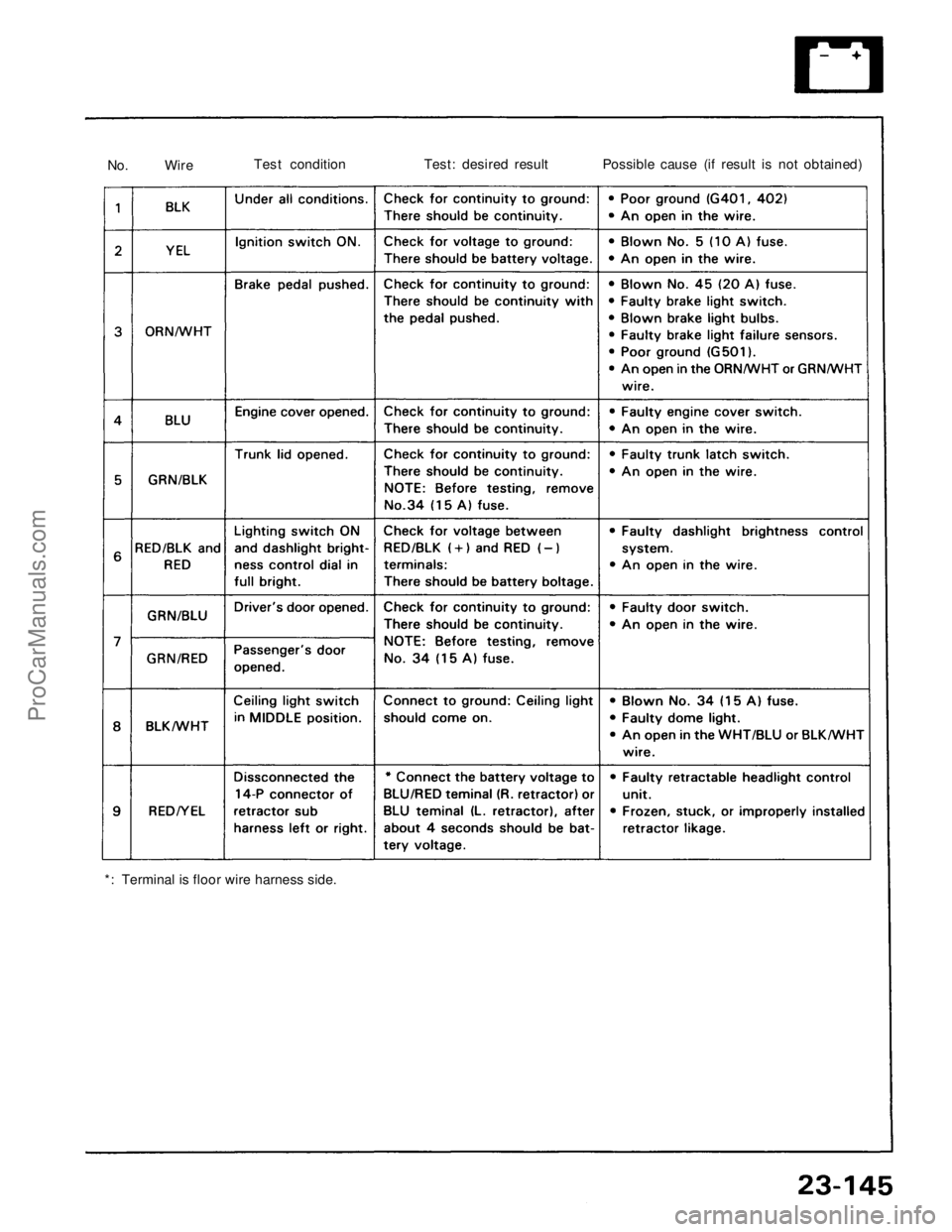
*: Terminal is floor wire harness side.No. Wire
Test condition
Test: desired result Possible cause (if result is not obtained)ProCarManuals.com
Page 1596 of 1640
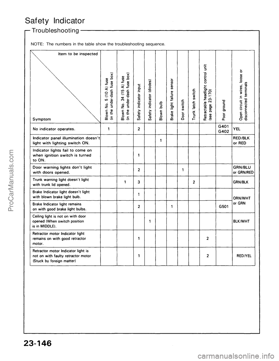
Safety Indicator
Troubleshooting
NOTE: The numbers in the table show the troubleshooting sequence.ProCarManuals.com
Page 1597 of 1640
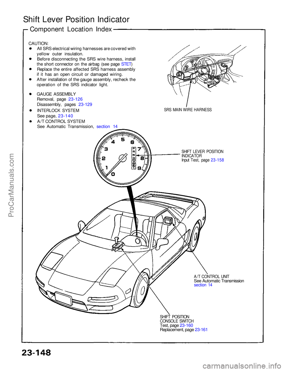
Shift Lever Position Indicator
CAUTION: All SRS electrical wiring harnesses are covered with
yellow outer insulation. Before disconnecting the SRS wire harness, install
the short connector on the airbag (see page STET) Replace the entire affected SRS harness assembly
if it has an open circuit or damaged wiring. After installation of the gauge assembly, recheck the
operation of the SRS indicator light.
GAUGE ASSEMBLY
Removal, page 23-126
Disassembly, pages 23-129
INTERLOCK SYSTEM
See page, 23-140
A/T CONTROL SYSTEM
See Automatic Transmission, section 14
SRS MAIN WIRE HARNESS
SHIFT LEVER POSITION
INDICATOR
Input Test, page 23-158
A/T CONTROL UNIT
See Automatic Transmission
section 14
SHIFT POSITION
CONSOLE SWITCH
Test, page 23-160
Replacement, page 23-161
Component Location IndexProCarManuals.com
Page 1598 of 1640
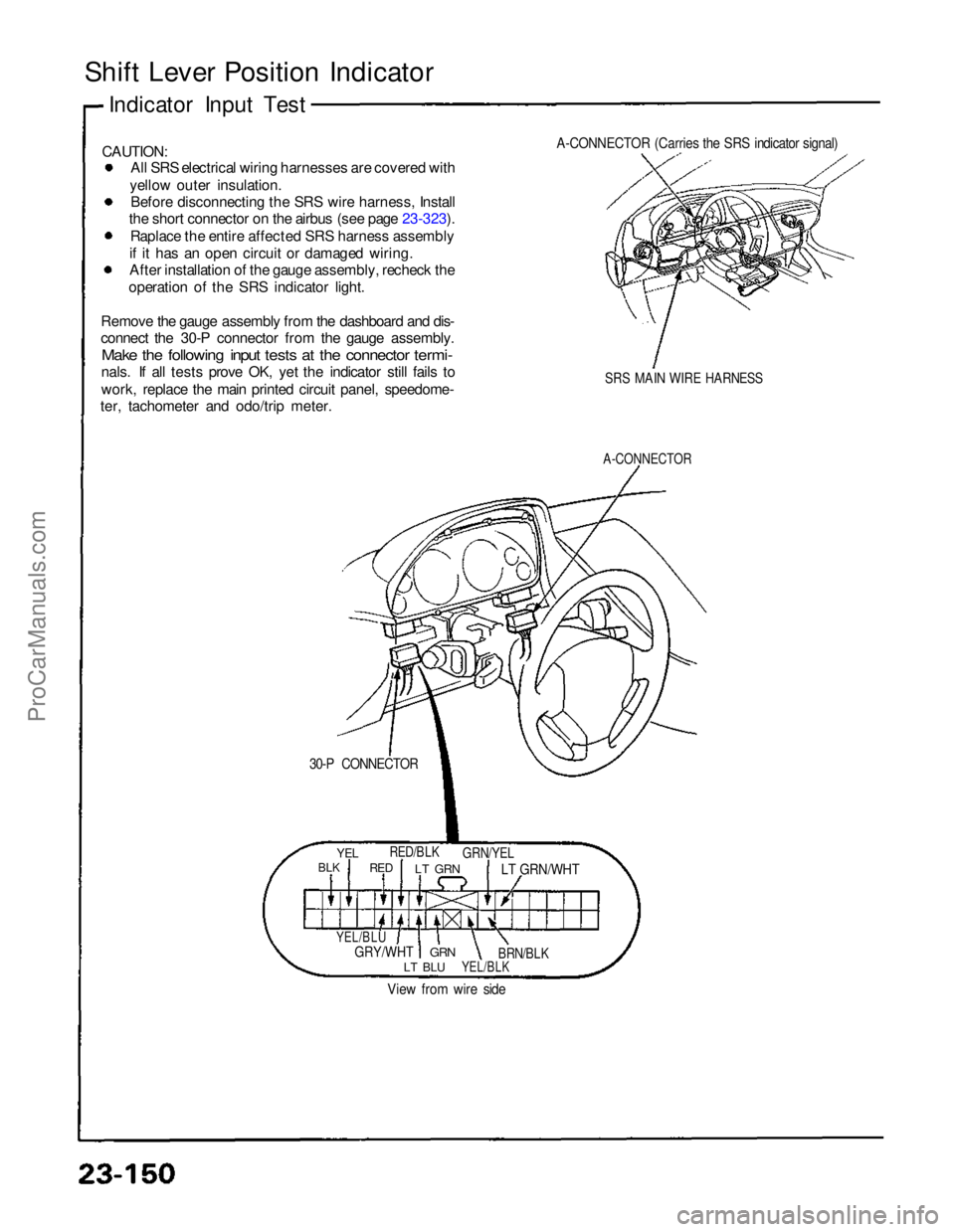
Shift Lever Position Indicator
CAUTION: All SRS electrical wiring harnesses are covered with
yellow outer insulation. Before disconnecting the SRS wire harness, Install
the short connector on the airbus (see page 23-323). Raplace the entire affected SRS harness assembly
if it has an open circuit or damaged wiring. After installation of the gauge assembly, recheck the
operation of the SRS indicator light.
Remove the gauge assembly from the dashboard and dis-
connect the 30-P connector from the gauge assembly.
Make the following input tests at the connector termi-
nals. If all tests prove OK, yet the indicator still fails to
work, replace the main printed circuit panel, speedome-
ter, tachometer and odo/trip meter.
A-CONNECTOR (Carries the SRS indicator signal)
SRS MAIN WIRE HARNESS
A-CONNECTOR
30-P CONNECTOR
Indicator Input Test
YEL
BLK
RED/BLK
RED
LT GRN
GRN/YEL
LT GRN/WHT
YEL/BLU
GRY/WHT
GRN
LT BLU
YEL/BLK
BRN/BLK
View from wire sideProCarManuals.com
Page 1599 of 1640
Page 1600 of 1640
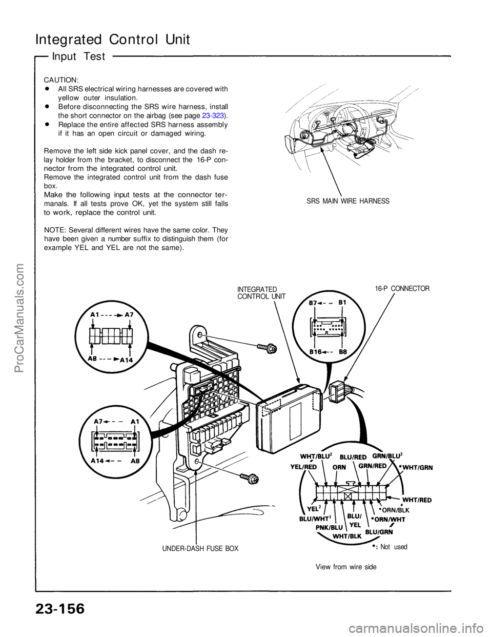
Integrated Control Unit
Input Test
CAUTION: All SRS electrical wiring harnesses are covered with
yellow outer insulation.Before disconnecting the SRS wire harness, install
the short connector on the airbag (see page 23-323). Replace the entire affected SRS harness assembly
if it has an open circuit or damaged wiring.
Remove the left side kick panel cover, and the dash re-
lay holder from the bracket, to disconnect the 16-P con-
nector from the integrated control unit.
Remove the integrated control unit from the dash fuse box.
Make the following input tests at the connector ter-
manals. If all tests prove OK, yet the system still falls
to work, replace the control unit.
NOTE: Several different wires have the same color. They
have been given a number suffix to distinguish them (for
example YEL and YEL are not the same).
SRS MAIN WIRE HARNESS
INTEGRATED
CONTROL UNIT
16-P CONNECTOR
UNDER-DASH FUSE BOX Not used
View from wire sideProCarManuals.com
Trending: fuel, wiring, clutch, alternator belt, check oil, OBD port, turn signal
