ACURA NSX 1991 Service Repair Manual
Manufacturer: ACURA, Model Year: 1991, Model line: NSX, Model: ACURA NSX 1991Pages: 1640, PDF Size: 60.48 MB
Page 531 of 1640
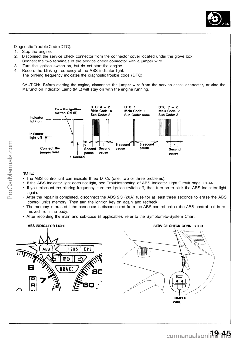
Diagnostic Trouble Code (DTC):
1. Stop the engine.
2. Disconnect the service check connector from the connector cover located under the glove box.
Connect the two terminals of the service check connector with a jumper wire.
3. Turn the ignition switch on, but do not start the engine.
4. Record the blinking frequency of the ABS indicator light.
The blinking frequency indicates the diagnostic trouble code (DTC).
CAUTION: Before starting the engine, disconnect the jumper wire from the service check connector, or else the
Malfunction Indicator Lamp (MIL) will stay on with the engine running.
NOTE:
• The ABS control unit can indicate three DTCs (one, two or three problems).
• If the ABS indicator light does not light, see Troubleshooting of ABS Indicator Light Circuit page 19-44.
• If you miscount the blinking frequency, turn the ignition switch off, then turn on to blink the ABS indicator light
again.
• After the repair is completed, disconnect the ABS 2,3 (20A) fuse for at least three seconds to erase the ABS
control unit's memory. Then turn the ignition key on again and recheck.
• The memory is erased if the connector is disconnected from the ABS control unit or the ABS control unit is re-
moved from the body.
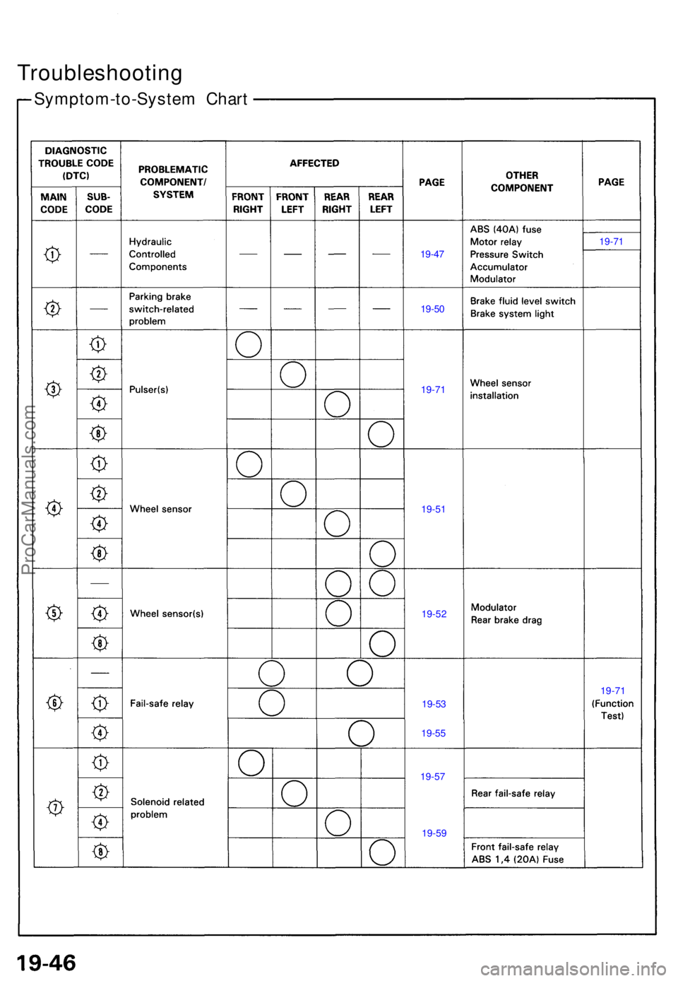
• After recording the main and sub-code (if applicable), refer to the Symptom-to-System Chart.ProCarManuals.com
Page 532 of 1640
Troubleshooting
Symptom-to-Syste m Char t
19-47
19-5 0
19-7 1
19-71
19-5 1
19-5 2
19-5 3 19-7
1
19-5 7
19-5
5
19-5 9
ProCarManuals.com
Page 533 of 1640
Hydraulic Syste m
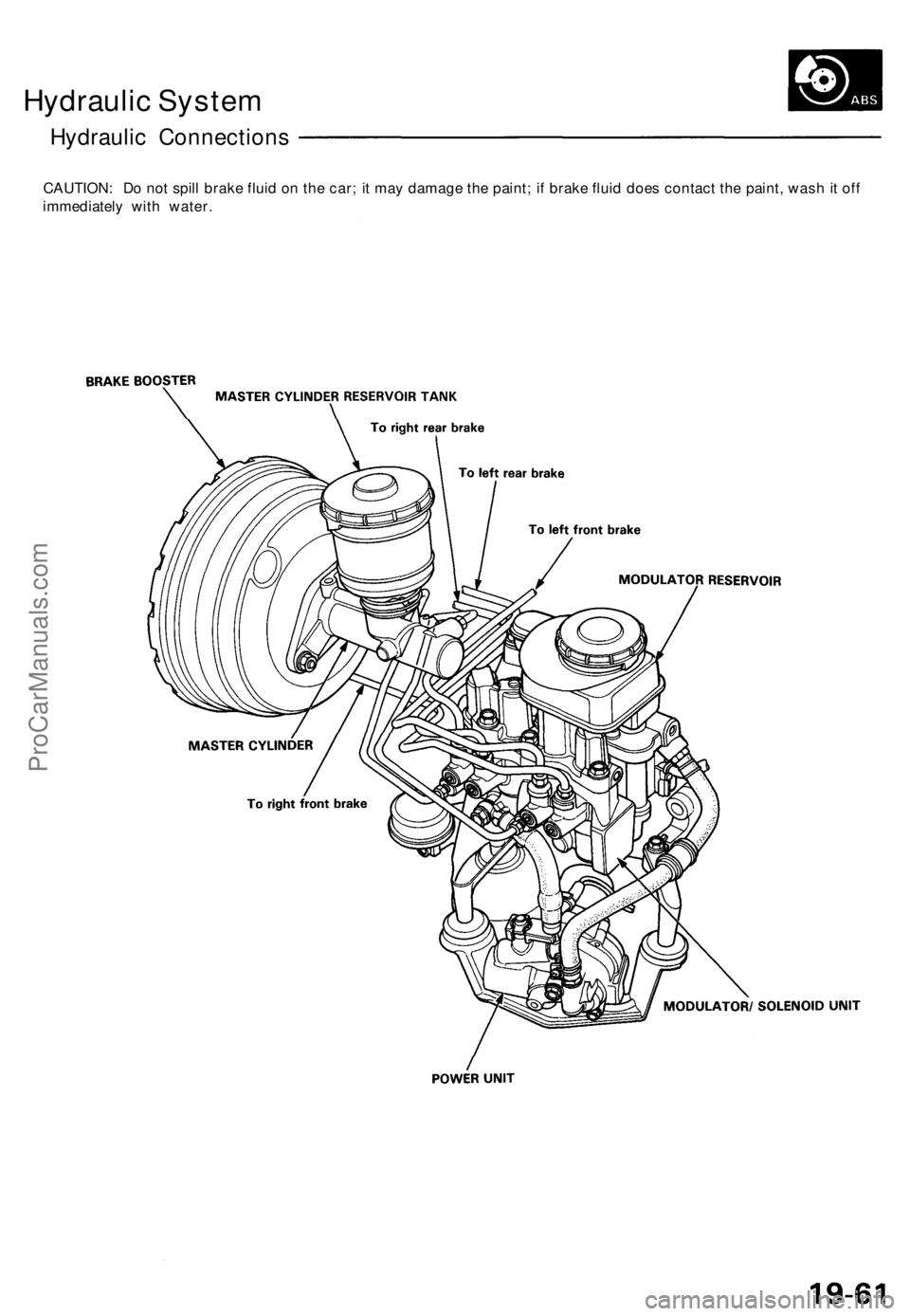
Hydrauli c Connection s
CAUTION: D o no t spil l brak e flui d o n th e car ; i t ma y damag e th e paint ; i f brak e flui d doe s contac t th e paint , was h it of f
immediatel y wit h water .
ProCarManuals.com
Page 534 of 1640
Hydraulic Syste m
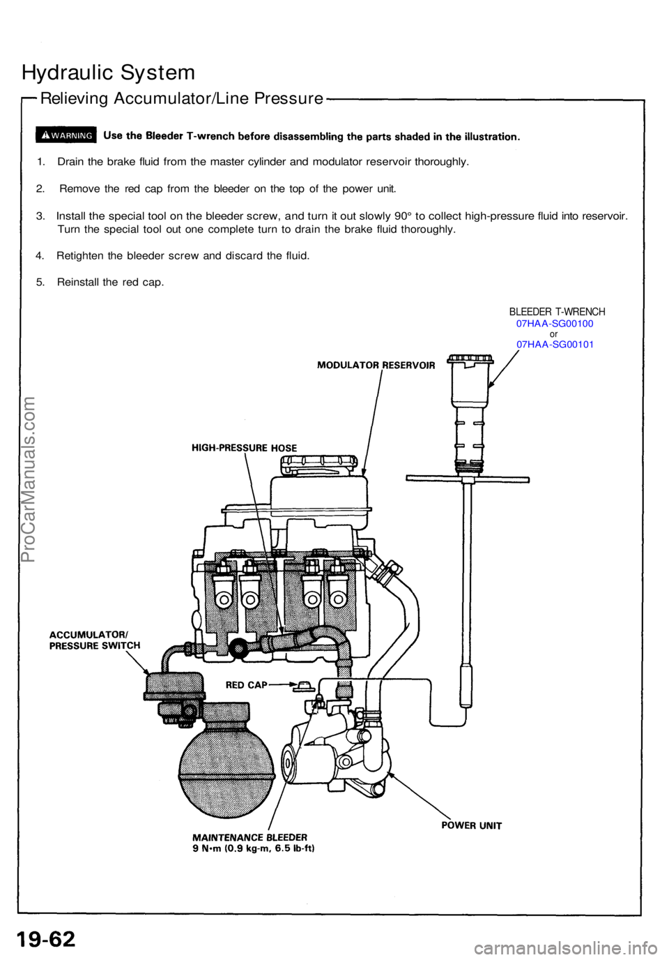
Relievin g Accumulator/Lin e Pressur e
1. Drai n th e brak e flui d fro m th e maste r cylinde r an d modulato r reservoi r thoroughly .
2. Remov e th e re d ca p fro m th e bleede r o n th e to p o f th e powe r unit .
3. Instal l th e specia l too l o n th e bleede r screw , an d tur n it ou t slowl y 90 ° t o collec t high-pressur e flui d int o reservoir .
Turn th e specia l too l ou t on e complet e tur n t o drai n th e brak e flui d thoroughly .
4 . Retighte n th e bleede r scre w an d discar d th e fluid .
5 . Reinstal l th e re d cap .
BLEEDE R T-WRENC H07HAA-SG0010 0or07HAA-SG0010 1
ProCarManuals.com
Page 535 of 1640
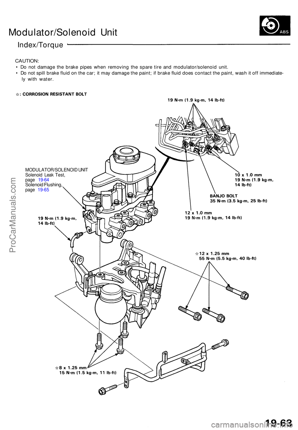
Modulator/Solenoid Uni t
Index/Torqu e
CAUTION:
• D o no t damag e th e brak e pipe s whe n removin g th e spar e tir e an d modulator/solenoi d unit .
• D o no t spil l brak e flui d o n th e car ; i t ma y damag e th e paint ; i f brak e flui d doe s contac t th e paint , was h it of f immediate -
l y wit h water .
MODULATOR/SOLENOI D UNI TSolenoi d Lea k Test ,page 19-6 4Solenoi d Flushing ,page 19-6 5
ProCarManuals.com
Page 536 of 1640
Modulator/Solenoid Uni t
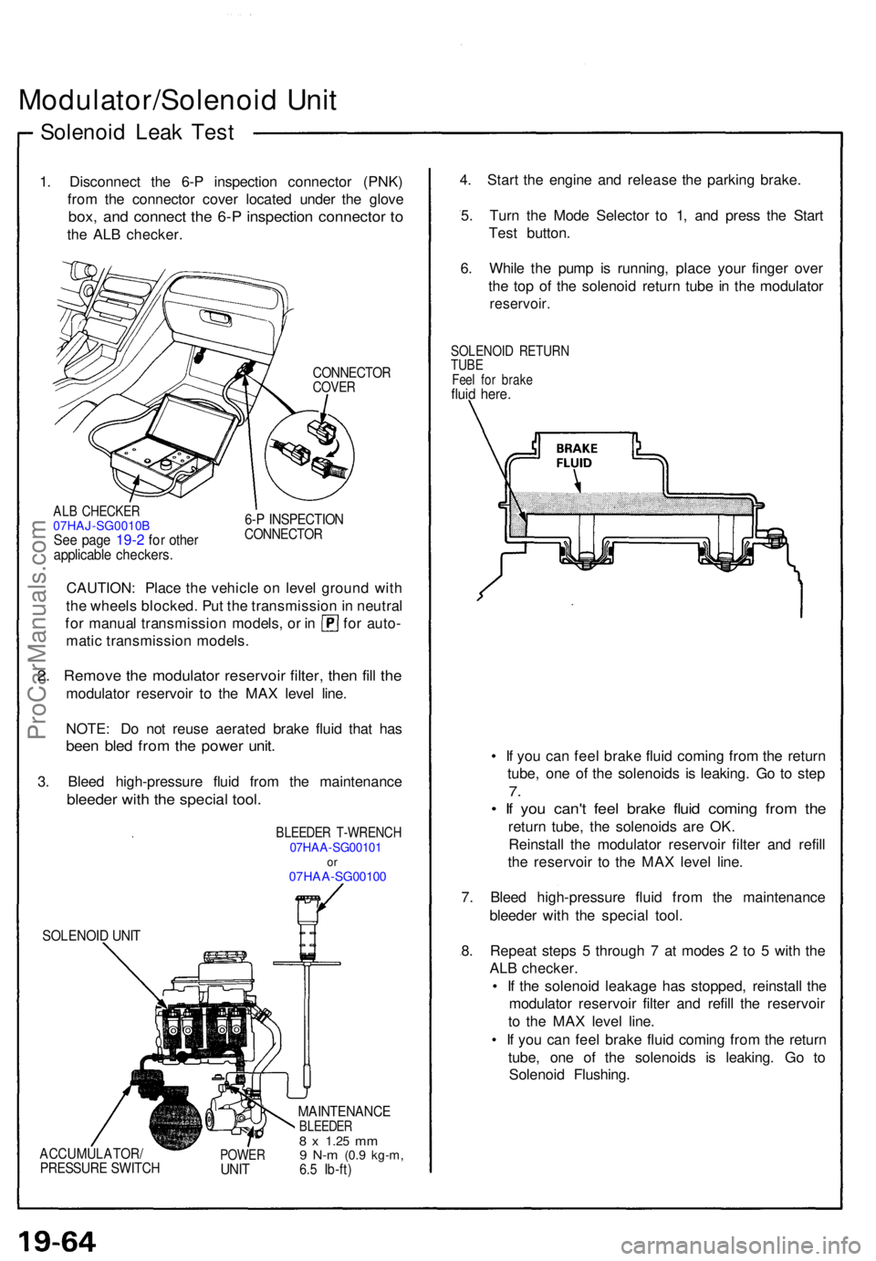
Solenoi d Lea k Tes t
1. Disconnec t th e 6- P inspectio n connecto r (PNK )
fro m th e connecto r cove r locate d unde r th e glov e
box, an d connec t th e 6- P inspectio n connecto r t o
th e AL B checker .
CONNECTO RCOVER
ALB CHECKE R07HAJ-SG0010BSe e pag e 19-2 fo r othe rapplicabl e checkers .
6-P INSPECTIO NCONNECTO R
CAUTION: Plac e th e vehicl e o n leve l groun d wit h
th e wheel s blocked . Pu t th e transmissio n in neutra l
for manua l transmissio n models , o r i n fo r auto -
mati c transmissio n models .
2. Remov e th e modulato r reservoi r filter , the n fil l th e
modulato r reservoi r t o th e MA X leve l line .
NOTE : D o no t reus e aerate d brak e flui d tha t ha s
bee n ble d fro m th e powe r unit .
3. Blee d high-pressur e flui d fro m th e maintenanc e
bleeder with the specia l tool .
BLEEDE R T-WRENC H07HAA-SG0010 1or07HA A-SG0010 0
SOLENOI D UNI T
ACCUMULATOR /PRESSURE SWITC HPOWERUNIT
MAINTENANC EBLEEDER8 x 1.2 5 mm9 N- m (0. 9 kg-m ,6.5 Ib-ft )
4. Star t th e engin e an d releas e th e parkin g brake .
5 . Tur n th e Mod e Selecto r t o 1 , an d pres s th e Star t
Tes t button .
6 . Whil e th e pum p i s running , plac e you r finge r ove r
th e to p o f th e solenoi d retur n tub e in th e modulato r
reservoir.
SOLENOI D RETUR NTUBEFeel fo r brak efluid here .
• I f yo u ca n fee l brak e flui d comin g fro m th e retur n
tube , on e o f th e solenoid s i s leaking . G o t o ste p
7.
• I f yo u can' t fee l brak e flui d comin g fro m th e
retur n tube , th e solenoid s ar e OK .
Reinstal l th e modulato r reservoi r filte r an d refil l
th e reservoi r t o th e MA X leve l line .
7 . Blee d high-pressur e flui d fro m th e maintenanc e
bleede r wit h th e specia l tool .
8 . Repea t step s 5 throug h 7 at mode s 2 to 5 wit h th e
AL B checker .
• I f th e solenoi d leakag e ha s stopped , reinstal l th e
modulato r reservoi r filte r an d refil l th e reservoi r
t o th e MA X leve l line .
• I f yo u ca n fee l brak e flui d comin g fro m th e retur n
tube , on e o f th e solenoid s i s leaking . G o t o
Solenoi d Flushing .
ProCarManuals.com
Page 537 of 1640
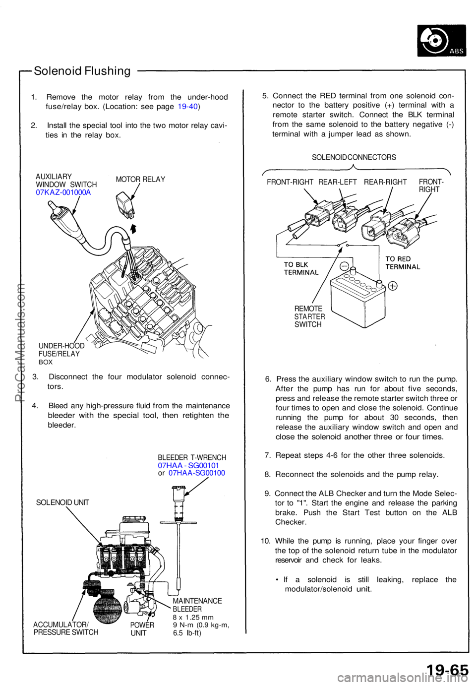
Solenoid Flushin g
1. Remov e th e moto r rela y fro m th e under-hoo d
fuse/rela y box . (Location : se e pag e 19-40 )
2 . Instal l th e specia l too l int o th e tw o moto r rela y cavi -
tie s i n th e rela y box .
AUXILIAR Y
WINDO W SWITC H
07KAZ-001000 A
MOTOR RELA Y
UNDER-HOO DFUSE/RELAYBOX
3. Disconnec t th e fou r modulato r solenoi d connec -
tors .
4 . Blee d an y high-pressur e flui d fro m th e maintenanc e
bleeder wit h th e specia l tool , the n retighte n th e
bleeder .
SOLENOI D UNI T
BLEEDE R T-WRENC H07HAA - SG0010 1or 07HA A-SG0010 0
ACCUMULATOR /
PRESSUR E SWITC HPOWERUNIT
MAINTENANC EBLEEDER8 x 1.2 5 mm9 N- m (0. 9 kg-m ,6.5 Ib-ft )
5. Connec t th e RE D termina l fro m on e solenoi d con -
necto r t o th e batter y positiv e (+ ) termina l wit h a
remot e starte r switch . Connec t th e BL K termina l
fro m th e sam e solenoi d t o th e batter y negativ e (- )
termina l wit h a jumpe r lea d a s shown .
SOLENOI D CONNECTOR S
FRONT-RIGH T REAR-LEF T REAR-RIGH T
FRONT-RIGHT
REMOT ESTARTE RSWITCH
6. Pres s th e auxiliar y windo w switc h t o ru n th e pump .
Afte r th e pum p ha s ru n fo r abou t fiv e seconds ,
pres s an d releas e th e remot e starte r switc h thre e o r
fou r time s t o ope n an d clos e th e solenoid . Continu e
runnin g th e pum p fo r abou t 3 0 seconds , the n
releas e th e auxiliar y windo w switc h an d ope n an d
clos e th e solenoi d anothe r thre e o r fou r times .
7. Repea t step s 4- 6 fo r th e othe r thre e solenoids .
8 . Reconnec t th e solenoid s an d th e pum p relay .
9 . Connec t th e AL B Checke r an d tur n th e Mod e Selec -
to r t o "1" . Star t th e engin e an d releas e th e parkin g
brake . Pus h th e Star t Tes t butto n o n th e AL B
Checker .
10. Whil e th e pum p i s running , plac e you r finge r ove r
th e to p o f th e solenoi d retur n tub e in th e modulato r
reservoi r an d chec k fo r leaks .
• I f a solenoi d i s stil l leaking , replac e th e
modulator/solenoi d
unit.
ProCarManuals.com
Page 538 of 1640
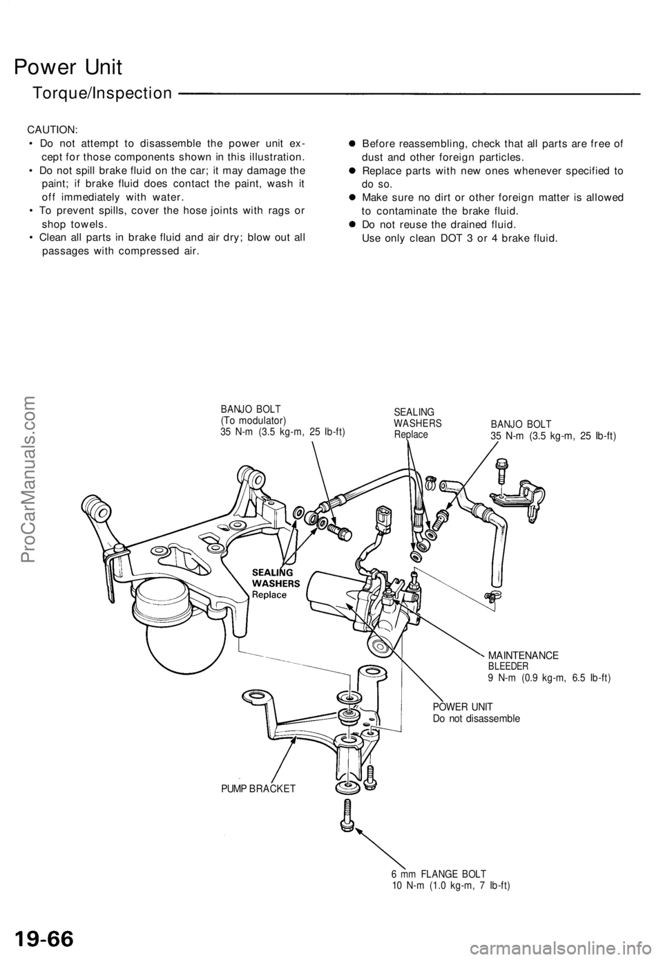
Power Uni t
Torque/Inspectio n
CAUTION:
• D o no t attemp t t o disassembl e th e powe r uni t ex -
cep t fo r thos e component s show n in thi s illustration .
• D o no t spil l brak e flui d o n th e car ; i t ma y damag e th e
paint ; i f brak e flui d doe s contac t th e paint , was h i t
of f immediatel y wit h water .
• T o preven t spills , cove r th e hos e joint s wit h rag s o r
sho p towels .
• Clea n al l part s i n brak e flui d an d ai r dry ; blo w ou t al l
passage s wit h compresse d air . Befor
e reassembling , chec k tha t al l part s ar e fre e o f
dus t an d othe r foreig n particles .
Replac e part s wit h ne w one s wheneve r specifie d t o
do so .
Mak e sur e n o dir t o r othe r foreig n matte r i s allowe d
t o contaminat e th e brak e fluid .
D o no t reus e th e draine d fluid .
Us e onl y clea n DO T 3 o r 4 brak e fluid .
BANJ O BOL T(To modulator )35 N- m (3. 5 kg-m , 2 5 Ib-ft )
SEALIN GWASHER SReplaceBANJO BOL T35 N- m (3. 5 kg-m , 2 5 Ib-ft )
MAINTENANC EBLEEDER9 N- m (0. 9 kg-m , 6. 5 Ib-ft )
POWE R UNI TDo no t disassembl e
PUMP BRACKE T
6 m m FLANG E BOL T10 N- m (1. 0 kg-m , 7 Ib-ft )
ProCarManuals.com
Page 539 of 1640
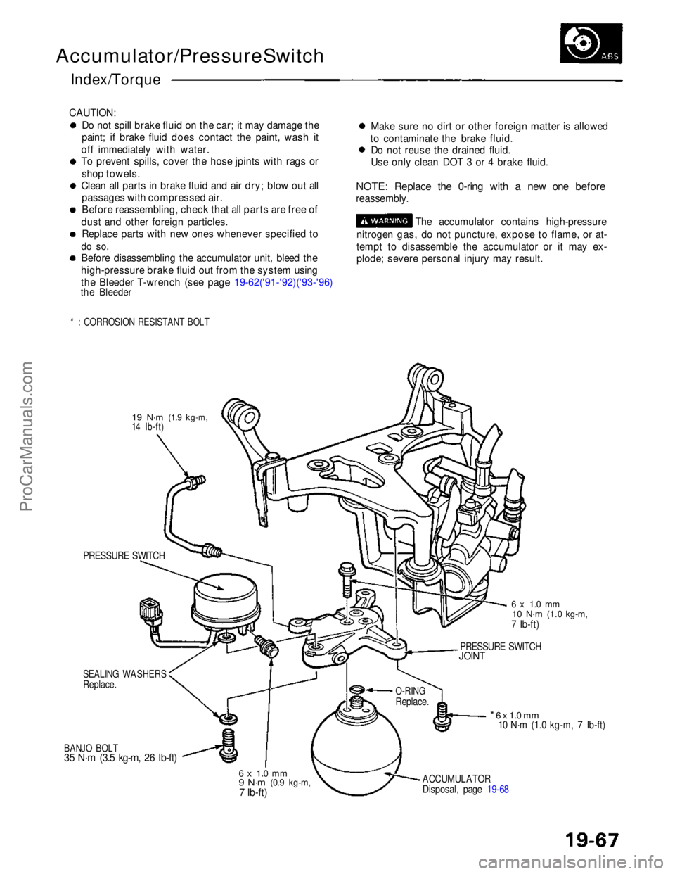
Accumulator/Pressure Switch
Index/Torque
CAUTION: Do not spill brake fluid on the car; it may damage the
paint; if brake fluid does contact the paint, wash it
off immediately with water.
To prevent spills, cover the hose jpints with rags or shop towels.
Clean all parts in brake fluid and air dry; blow out all passages with compressed air.
Before reassembling, check that all parts are free of
dust and other foreign particles. Replace parts with new ones whenever specified to
do so.
Before disassembling the accumulator unit, bleed the
high-pressure brake fluid out from the system using
the Bleeder T-wrench (see page 19-62('91-'92)('93-'96)
the Bleeder
*: CORROSION RESISTANT BOLT
Make sure no dirt or other foreign matter is allowed
to contaminate the brake fluid. Do not reuse the drained fluid.
Use only clean DOT 3 or 4 brake fluid.
NOTE: Replace the 0-ring with a new one before
reassembly. The accumulator contains high-pressure
nitrogen gas, do not puncture, expose to flame, or at-
tempt to disassemble the accumulator or it may ex-
plode; severe personal injury may result.
19 N·m
(1.9 kg-m,
14 Ib-ft)
PRESSURE SWITCH
SEALING WASHERS
Replace.
BANJO BOLT
35 N·m (3.5 kg-m, 26 Ib-ft)
6 x 1.0 mm
9 N·m
(0.9 kg-m,7 Ib-ft)
ACCUMULATOR
Disposal, page 19-68
* 6 x 1.0 mm
10 N·m (1.0 kg-m, 7 Ib-ft)
O-RING
Replace.
PRESSURE SWITCH
JOINT
6 x 1.0 mm
10 N·m
(1.0 kg-m,
7 Ib-ft)ProCarManuals.com
Page 540 of 1640
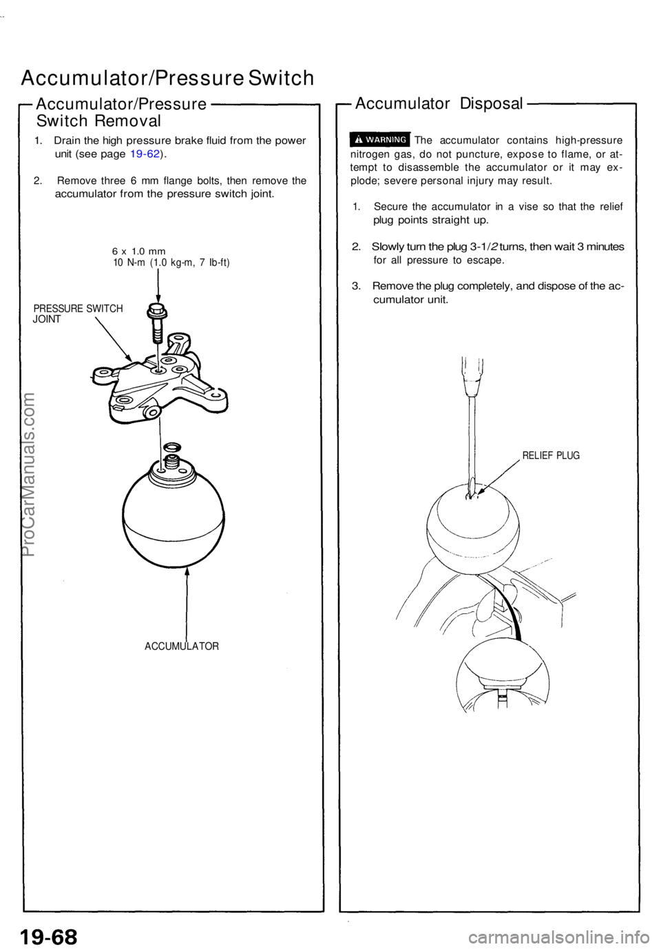
Accumulator/Pressure Switc h
Accumulator/Pressur e
Switc h Remova l
1. Drai n th e hig h pressur e brak e flui d fro m th e powe r
unit (se e pag e 19-62 ).
2 . Remov e thre e 6 m m flang e bolts , the n remov e th e
accumulato r fro m th e pressur e switc h joint .
6 x 1. 0 m m10 N- m (1. 0 kg-m , 7 Ib-ft )
PRESSUR E SWITC HJOINT
ACCUMULATO R
Accumulator Disposa l
The accumulato r contain s high-pressur e
nitroge n gas , d o no t puncture , expos e t o flame , o r at -
temp t t o disassembl e th e accumulato r o r i t ma y ex -
plode ; sever e persona l injur y ma y result .
1 . Secur e th e accumulato r i n a vis e s o tha t th e relie f
plug point s straigh t up .
2. Slowl y tur n th e plu g 3-1/ 2 turns , the n wai t 3 minute s
for al l pressur e t o escape .
3. Remov e th e plu g completely , an d dispos e o f th e ac -
cumulato r unit .
RELIE F PLU G
ProCarManuals.com