ACURA NSX 1991 Service Repair Manual
Manufacturer: ACURA, Model Year: 1991, Model line: NSX, Model: ACURA NSX 1991Pages: 1640, PDF Size: 60.48 MB
Page 551 of 1640
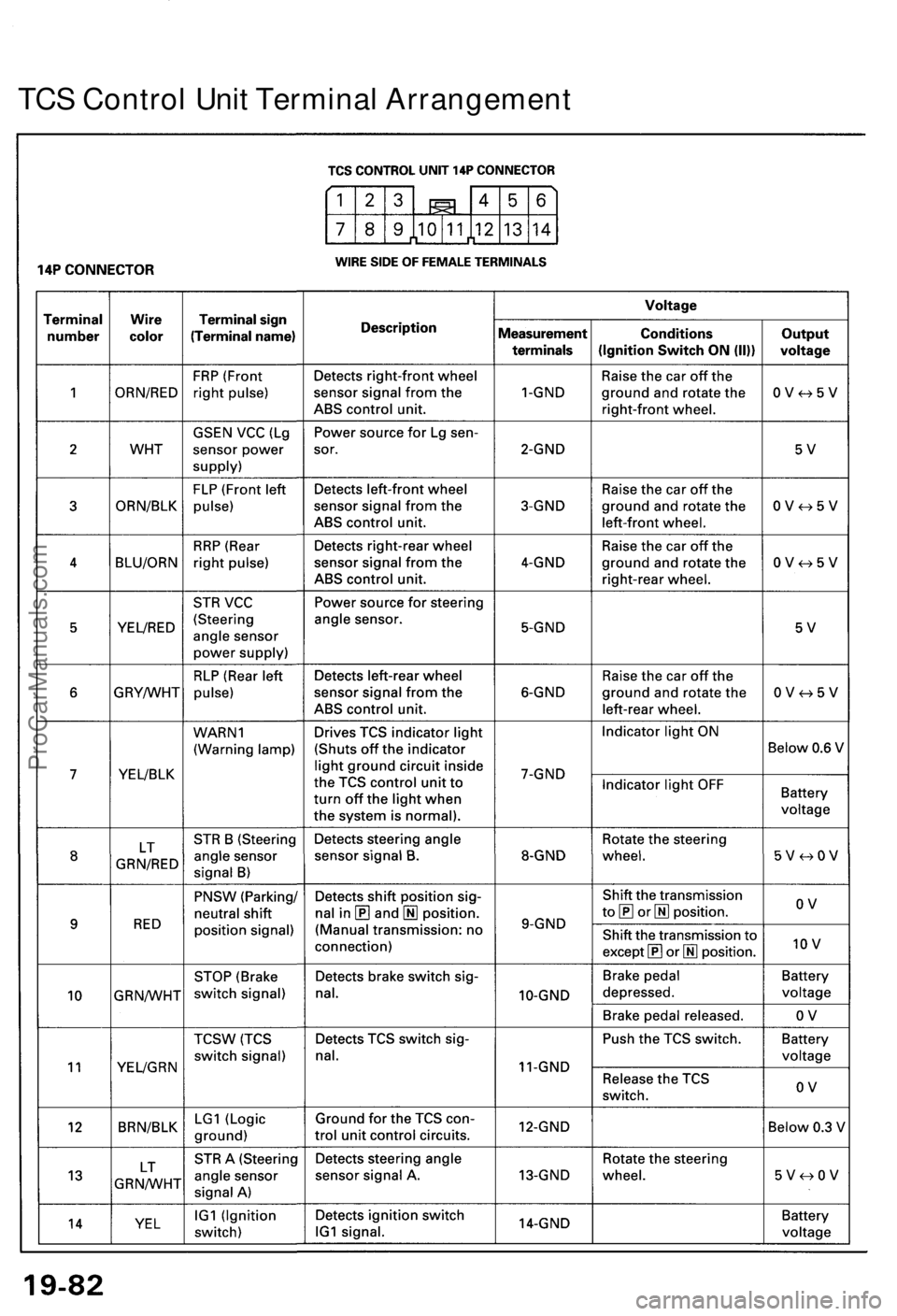
TCS Contro l Uni t Termina l Arrangemen t
ProCarManuals.com
Page 552 of 1640
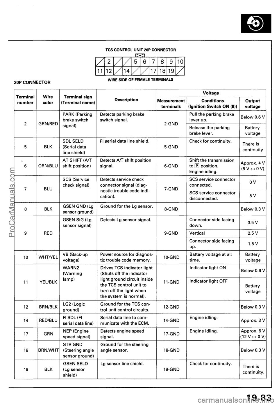
ProCarManuals.com
Page 553 of 1640
Troubleshooting
TCS Indicato r Ligh t
Temporar y Drivin g Conditions :
1 . Th e TC S indicato r ligh t wil l com e o n an d th e contro l uni t memorize s th e Diagnosti c Troubl e Cod e (DTC ) unde r certai n
temporar y conditions :
• Th e spar e tir e is installed , o r a tir e o f th e imprope r siz e is installed .
• Th e tir e pressure s ar e no t correct .
2 . I f th e TC S indicato r ligh t doe s no t com e bac k o n afte r correctin g th e tir e o r tir e pressur e problem , th e TC S syste m is
OK .
3. Remov e th e CLOC K (7. 5 A ) fus e fo r a t leas t thre e second s to clea r th e DT C fro m th e TC S contro l uni t memory .
NOTE : Disconnectin g th e CLOC K fus e als o cancel s th e radi o prese t station s an d th e cloc k setting . Mak e not e o f th e
radi o preset s befor e removin g th e fus e s o yo u ca n rese t them .
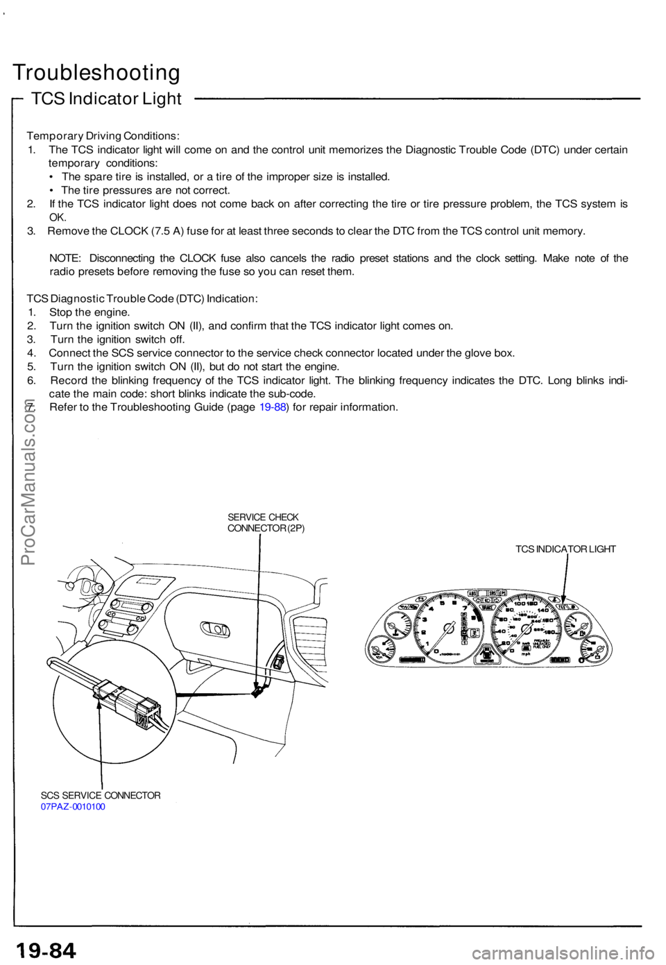
TC S Diagnosti c Troubl e Cod e (DTC ) Indication :
1 . Sto p th e engine .
2 . Tur n th e ignitio n switc h O N (II) , an d confir m tha t th e TC S indicato r ligh t come s on .
3 . Tur n th e ignitio n switc h off .
4 . Connec t th e SC S servic e connecto r t o th e servic e chec k connecto r locate d unde r th e glov e box .
5 . Tur n th e ignitio n switc h O N (II) , bu t d o no t star t th e engine .
6 . Recor d th e blinkin g frequenc y o f th e TC S indicato r light . Th e blinkin g frequenc y indicate s th e DTC . Lon g blink s indi -
cat e th e mai n code : shor t blink s indicat e th e sub-code .
7 . Refe r t o th e Troubleshootin g Guid e (pag e 19-88 ) fo r repai r information .
SERVICE CHEC KCONNECTO R (2P )
TCS INDICATO R LIGH T
SCS SERVIC E CONNECTO R07PAZ-001010 0
ProCarManuals.com
Page 554 of 1640
NOTE:
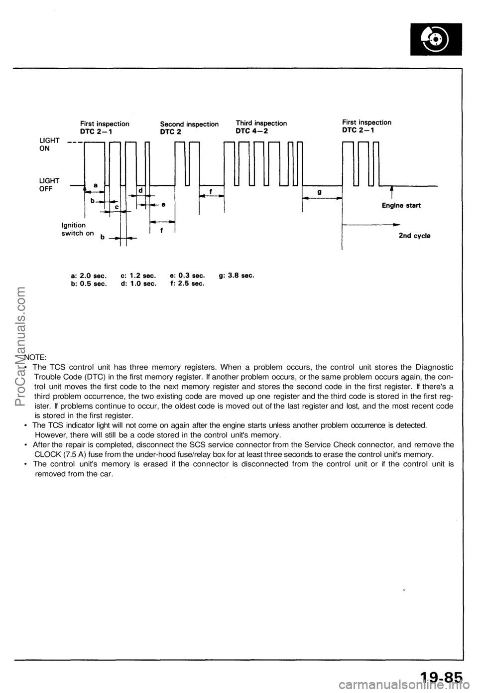
• Th e TC S contro l uni t ha s thre e memor y registers . Whe n a proble m occurs , th e contro l uni t store s th e Diagnosti c
Troubl e Cod e (DTC ) i n th e firs t memor y register . I f anothe r proble m occurs , o r th e sam e proble m occur s again , th e con -
tro l uni t move s th e firs t cod e t o th e nex t memor y registe r an d store s th e secon d cod e i n th e firs t register . I f there' s a
thir d proble m occurrence , th e tw o existin g cod e ar e move d u p on e registe r an d th e thir d cod e is store d in th e firs t reg -
ister . I f problem s continu e t o occur , th e oldes t cod e is move d ou t o f th e las t registe r an d lost , an d th e mos t recen t cod e
i s store d in th e firs t register .
• Th e TC S indicato r ligh t wil l no t com e o n agai n afte r th e engin e start s unles s anothe r proble m occurrenc e is detected .
However , ther e wil l stil l b e a cod e store d in th e contro l unit' s memory .
• Afte r th e repai r i s completed , disconnec t th e SC S servic e connecto r fro m th e Servic e Chec k connector , an d remov e th e
CLOC K (7. 5 A ) fus e fro m th e under-hoo d fuse/rela y bo x fo r a t leas t thre e second s to eras e th e contro l unit' s memory .
• Th e contro l unit' s memor y i s erase d i f th e connecto r i s disconnecte d fro m th e contro l uni t o r i f th e contro l uni t i s
remove d fro m th e car .
ProCarManuals.com
Page 555 of 1640
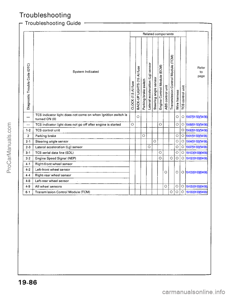
Troubleshooting
Troubleshooting Guide
Refer
to
page
19-87('91-'93)(''94-'96)
19-89('91-'93)(''94-'96)
19-90('91-'93)(''94-'96)
19-91('91-'93)(''94-'96)
19-94('91-'93)(''94-'96)
19-97('91-'93)(''94-'96)
19-100 ('91-'93)(''94-'96)
19-102 ('91-'93)(''94-'96)
19-103 ('91-'93)(''94-'96)
19-105 ('91-'93)(''94-'96)
19-106 ('91-'93)(''94-'96)
ProCarManuals.com
Page 556 of 1640
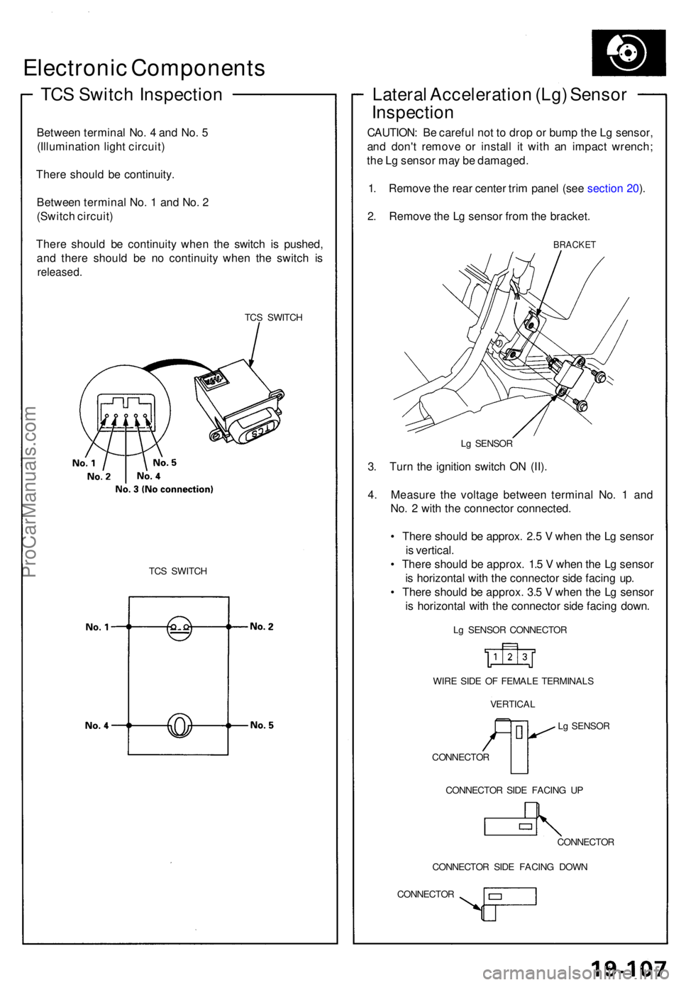
Electronic Component s
TCS Switc h Inspectio n
Between termina l No . 4 an d No . 5
(Illuminatio n ligh t circuit )
Ther e shoul d b e continuity .
Betwee n termina l No . 1 an d No . 2
(Switc h circuit )
Ther e shoul d b e continuit y whe n th e switc h i s pushed ,
an d ther e shoul d b e n o continuit y whe n th e switc h i s
released .
TCS SWITC H
TC S SWITC H
Lateral Acceleratio n (Lg ) Senso r
Inspectio n
CAUTION : B e carefu l no t t o dro p o r bum p th e L g sensor ,
an d don' t remov e o r instal l i t wit h a n impac t wrench ;
th e L g senso r ma y b e damaged .
1 . Remov e th e rea r cente r tri m pane l (se e sectio n 20 ).
2 . Remov e th e L g senso r fro m th e bracket .
BRACKE T
Lg SENSO R
3. Tur n th e ignitio n switc h O N (II) .
4 . Measur e th e voltag e betwee n termina l No . 1 an d
No . 2 wit h th e connecto r connected .
• Ther e shoul d b e approx . 2. 5 V whe n th e L g senso r
i s vertical .
• Ther e shoul d b e approx . 1. 5 V whe n th e L g senso r
i s horizonta l wit h th e connecto r sid e facin g up .
• Ther e shoul d b e approx . 3. 5 V whe n th e L g senso r
i s horizonta l wit h th e connecto r sid e facin g down .
Lg SENSO R CONNECTO R
WIR E SID E O F FEMAL E TERMINAL S
VERTICA L
Lg SENSO R
CONNECTO R
CONNECTO R SID E FACIN G U P
CONNECTO R
CONNECTO R SID E FACIN G DOW N
CONNECTO R
ProCarManuals.com
Page 557 of 1640
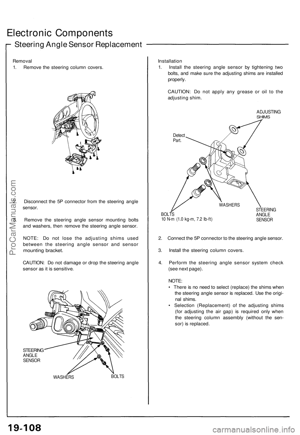
Electronic Component s
Steering Angl e Senso r Replacemen t
Removal
1 . Remov e th e steerin g colum n covers . Installatio
n
1 . Instal l th e steerin g angl e senso r b y tightenin g tw o
bolts , an d mak e sur e th e adjustin g shim s ar e installe d
properly .
CAUTION : D o no t appl y an y greas e o r oi l t o th e
adjustin g shim .
Detec tPart.
ADJUSTIN GSHIMS
2. Disconnec t th e 5 P connecto r fro m th e steerin g angl e
sensor .
3 . Remov e th e steerin g angl e senso r mountin g bolt s
an d washers , the n remov e th e steerin g angl e sensor .
NOTE : D o no t los e th e adjustin g shim s use d
betwee n th e steerin g angl e senso r an d senso r
mounting bracket .
CAUTION : D o no t damag e o r dro p th e steerin g angl e
senso r a s it i s sensitive .
STEERINGANGLESENSO R
WASHER S BOLT
S BOLT
S
1 0 N- m (1. 0 kg-m , 7. 2 Ib-ft ) STEERIN
G
ANGLESENSO R
2. Connec t th e 5 P connecto r t o th e steerin g angl e sensor .
3 . Instal l th e steerin g colum n covers .
4 . Perfor m th e steerin g angl e senso r syste m chec k
(se e nex t page) .
NOTE :
• Ther e is n o nee d to selec t (replace ) th e shim s whe n
th e steerin g angl e senso r i s replaced . Us e th e origi -
na l shims .
• Selectio n (Replacement ) o f th e adjustin g shim s
(fo r adjustin g th e ai r gap ) i s require d onl y whe n
th e steerin g colum n assembly (without th e sen -
sor ) i s replaced .
WASHER S
ProCarManuals.com
Page 558 of 1640
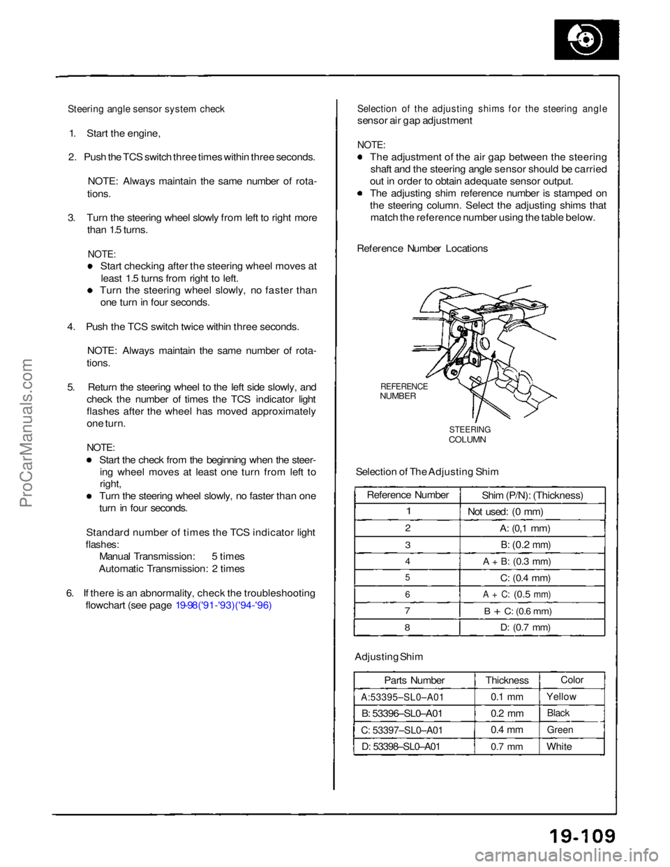
Steering angle sensor system check
1. Start the engine,
2. Push the TCS switch three times within three seconds.
NOTE: Always maintain the same number of rota-
tions.
3. Turn the steering wheel slowly from left to right more than 1.5 turns.
NOTE:
Start checking after the steering wheel moves at
least 1.5 turns from right to left.
Turn the steering wheel slowly, no faster than
one turn in four seconds.
4. Push the TCS switch twice within three seconds. NOTE: Always maintain the same number of rota-
tions.
5. Return the steering wheel to the left side slowly, and check the number of times the TCS indicator light
flashes after the wheel has moved approximately
one turn.
NOTE:
Start the check from the beginning when the steer-ing wheel moves at least one turn from left to
right, Turn the steering wheel slowly, no faster than one
turn in four seconds.
Standard number of times the TCS indicator light
flashes:
Manual Transmission: 5 times
Automatic Transmission: 2 times
6. If there is an abnormality, check the troubleshooting flowchart (see page 19-98('91-'93)('94-'96)
Selection of the adjusting shims for the steering angle
sensor air gap adjustment
NOTE:
The adjustment of the air gap between the steeringshaft and the steering angle sensor should be carried
out in order to obtain adequate sensor output.
The adjusting shim reference number is stamped on
the steering column. Select the adjusting shims that match the reference number using the table below.
Reference Number Locations
REFERENCE
NUMBER
STEERING
COLUMN
Selection of The Adjusting Shim
Adjusting Shim Parts Number
A:53395–SL0–A01
B: 53396–SL0–A01
C: 53397–SL0–A01
D: 53398–SL0–A01
Thickness
0.1 mm
0.2 mm
0.4 mm
0.7 mm
Color
Yellow
Black
Green
White
Reference Number
1
2
3
4
5
6
7
8
Shim (P/N): (Thickness)
Not used: (0 mm)
A:
(0,1
mm)
B:
(0.2
mm)
A + B:
(0.3
mm)
C:
(0.4
mm)
A + C:
(0.5
mm)
B + C:
(0.6
mm)
D:
(0.7
mm)ProCarManuals.com
Page 559 of 1640
Electronic Component s
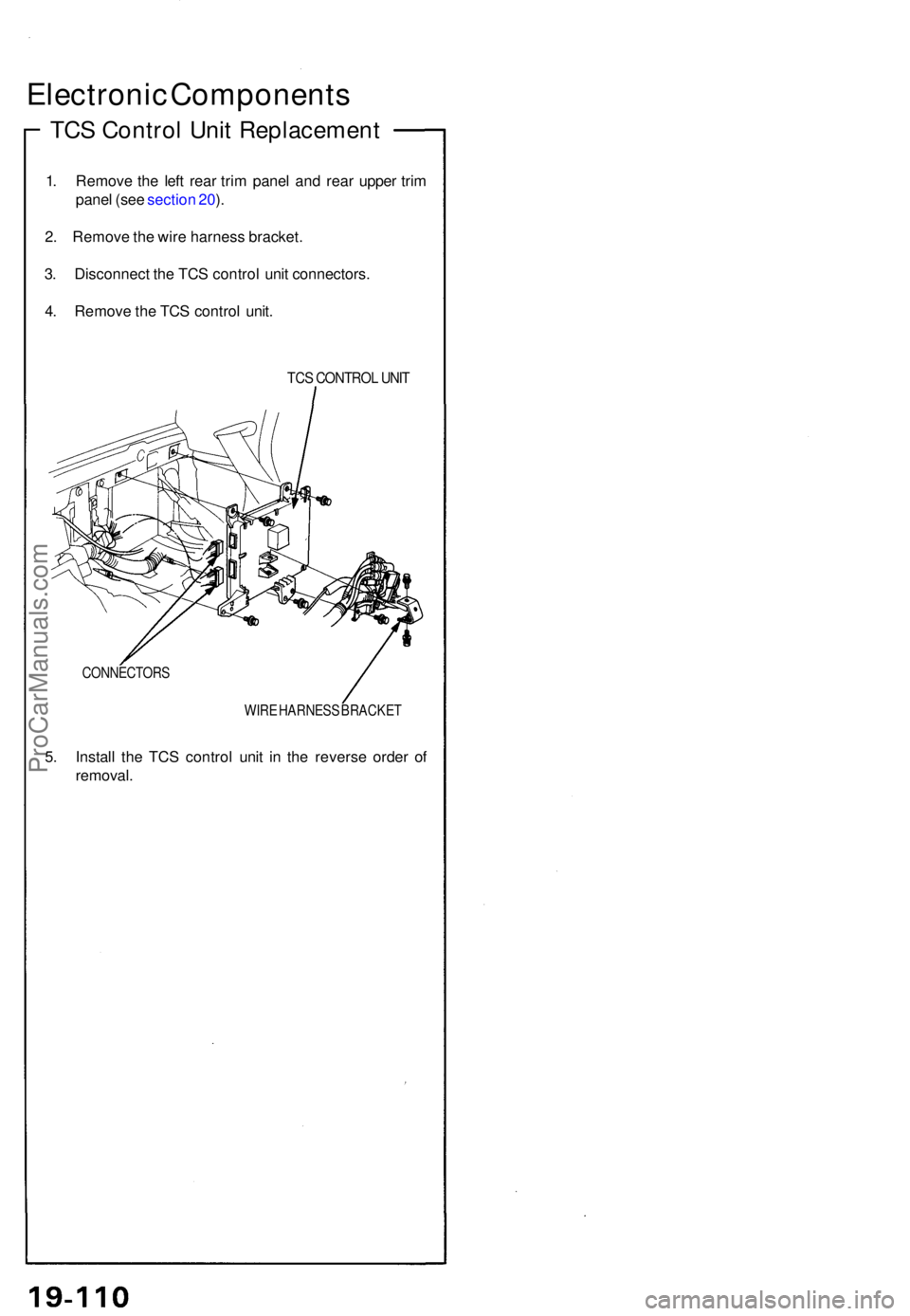
TCS Contro l Uni t Replacemen t
1. Remov e th e lef t rea r tri m pane l an d rea r uppe r tri m
pane l (se e sectio n 20 ).
2 . Remov e th e wir e harnes s bracket .
3 . Disconnec t th e TC S contro l uni t connectors .
4 . Remov e th e TC S contro l unit .
TCS CONTRO L UNI T
CONNECTOR S
WIRE HARNES S BRACKE T
5. Instal l th e TC S contro l uni t i n th e revers e orde r o f
removal .
ProCarManuals.com
Page 560 of 1640
Special Tools
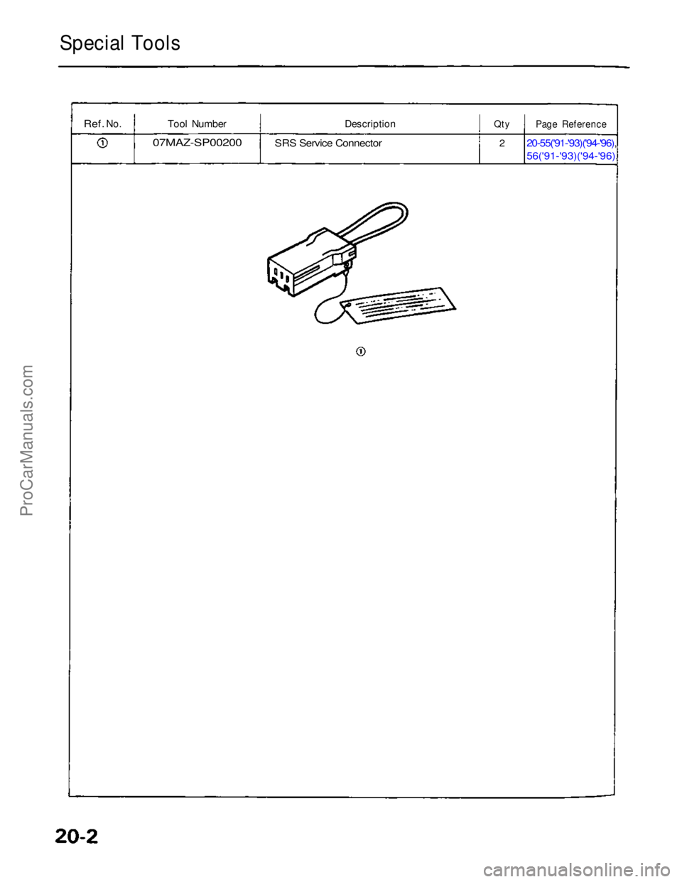
Ref.
No.
Tool Number
07MAZ-SP00200
Description
SRS Service Connector
Qty
2
Page Reference
20-55('91-'93)('94-'96),
56('91-'93)('94-'96),
ProCarManuals.com