ACURA NSX 1991 Service Repair Manual
Manufacturer: ACURA, Model Year: 1991, Model line: NSX, Model: ACURA NSX 1991Pages: 1640, PDF Size: 60.48 MB
Page 501 of 1640
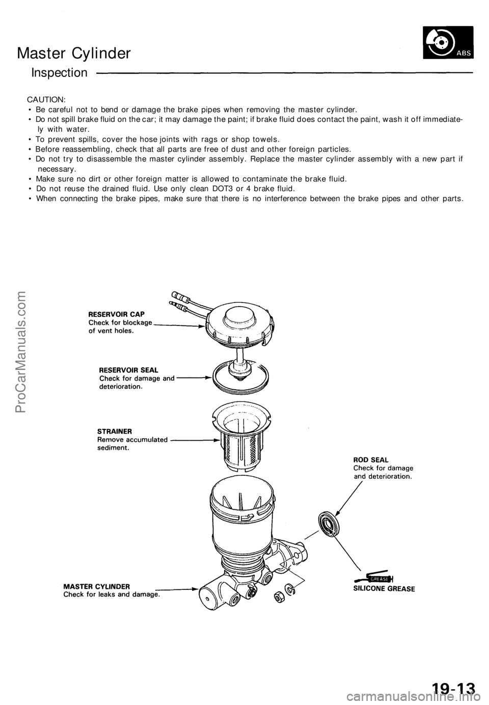
Master Cylinder
Inspection
CAUTION:
• Be careful not to bend or damage the brake pipes when removing the master cylinder.
• Do not spill brake fluid on the car; it may damage the paint; if brake fluid does contact the paint, wash it off immediate-
ly with water.
• To prevent spills, cover the hose joints with rags or shop towels.
• Before reassembling, check that all parts are free of dust and other foreign particles.
• Do not try to disassemble the master cylinder assembly. Replace the master cylinder assembly with a new part if
necessary.
• Make sure no dirt or other foreign matter is allowed to contaminate the brake fluid.
• Do not reuse the drained fluid. Use only clean DOT3 or 4 brake fluid.
• When connecting the brake pipes, make sure that there is no interference between the brake pipes and other parts.ProCarManuals.com
Page 502 of 1640
Brake Booste r
Tests
Functiona l Tes t
1. Wit h th e engin e stopped , depres s th e brak e peda l
severa l time s t o deplet e th e vacuu m reservoir , the n
depres s th e peda l har d an d hol d i t fo r 1 5 seconds .
I f th e peda l sinks , eithe r th e maste r cylinde r i s
bypassin g internally , o r th e brak e syste m (maste r
cylinder , lines , modulator , proportionin g valve , o r
calipers ) ar e leaking .
2 . Star t th e engin e wit h th e peda l depressed . I f th e pe -
da l sink s slightly , th e vacuu m booste r i s operatin g
normally , i f th e peda l heigh t doe s no t vary , th e
booste r o r chec k valv e i s faulty .
3 . Wit h th e engin e running , depres s th e brak e peda l
lightly . Appl y jus t enoug h pressur e t o hol d bac k au -
tomati c transmissio n creep . I f th e brak e peda l sink s
mor e tha n 2 5 m m (1. 0 in. ) i n thre e minutes , th e
maste r cylinde r i s faulty . A sligh t chang e i n peda l
heigh t whe n th e A/ C compresso r cycle s o n an d of f
i f normal . (Th e A/ C compresso r loa d change s th e
vacuu m availabl e t o th e booster. )
Leak Tes t
1. Depres s th e brak e peda l wit h th e engin e running ,
the n sto p th e engine . I f th e peda l heigh t doe s no t
var y whil e depresse d fo r 3 0 seconds , th e vacuu m
booste r i s OK . I f th e peda l rises , th e booste r i s faulty .
2 . Wit h th e engin e stopped , depres s th e brak e peda l
severa l time s usin g norma l pressure . Whe n th e pe -
da l i s firs t depressed , i t shoul d b e low . O n consecu -
tiv e applications , th e peda l heigh t shoul d graduall y
rise . I f th e peda l positio n doe s no t vary , chec k th e
booste r chec k valve .
Booste r Chec k Valv e Tes t
1. Disconnec t th e brak e booste r vacuu m hos e a t th e
booste r o r a t th e booste r sid e o f th e valve .
2 . Star t th e engin e an d le t i t idle . Ther e shoul d b e vacu -
um . I f n o vacuu m is available , th e chec k valv e is no t
workin g properly . Replac e th e chec k valv e an d
retest .
ProCarManuals.com
Page 503 of 1640
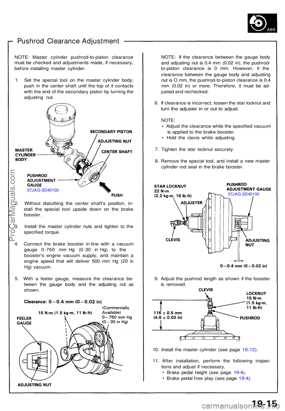
Pushrod Clearanc e Adjustmen t
NOTE: Maste r cylinde r pushrod-to-pisto n clearanc e
mus t b e checke d an d adjustment s made , i f necessary ,
befor e installin g maste r cylinder .
1 . Se t th e specia l too l o n th e maste r cylinde r body ;
pus h i n th e cente r shaf t unti l th e to p o f i t contact s
wit h th e en d o f th e secondar y pisto n b y turnin g th e
adjustin g nut .
07JAG-SD4010 0
2. Withou t disturbin g th e cente r shaft' s position , in -
stal l th e specia l too l upsid e dow n o n th e brak e
booster .
3 . Instal l th e maste r cylinde r nut s an d tighte n t o th e
specifie d torque .
4 . Connec t th e brak e booste r in-lin e wit h a vacuu m
gaug e 0-76 0 m m H g ( 0 -3 0 i n Hg ) t o th e
booster' s engin e vacuu m supply , an d maintai n a
engin e spee d tha t wil l delive r 50 0 m m H g (2 0 i n
Hg ) vacuum .
5 . Wit h a feele r gauge , measur e th e clearanc e be -
twee n th e gaug e bod y an d th e adjustin g nu t a s
shown . NOTE
: I f th e clearanc e betwee n th e gaug e bod y
an d adjustin g nu t i s 0. 4 m m (0.0 2 in) , th e pushrod -
to-pisto n clearanc e i s 0 mm . However , i f th e
clearanc e betwee n th e gaug e bod y an d adjustin g
nu t i s O mm , th e pushrod-to-pisto n clearanc e is 0. 4
m m (0.0 2 in ) o r more . Therefore , i t mus t b e ad -
juste d an d rechecked .
6 . I f clearanc e is incorrect , loose n th e sta r locknu t an d
turn th e adjuste r i n o r ou t t o adjust .
NOTE:
• Adjus t th e clearanc e whil e th e specifie d vacuu m
i s applie d t o th e brak e booster .
• Hol d th e clevi s whil e adjusting .
7 . Tighte n th e sta r locknu t securely .
8 . Remov e th e specia l tool , an d instal l a ne w maste r
cylinde r ro d sea l i n th e brak e booster .
07JAG-SD40100
9. Adjus t th e pushro d lengt h a s show n i f th e booste r
i s removed .
10 . Instal l th e maste r cylinde r (se e pag e 19-12 ).
11 . Afte r installation , perfor m th e followin g inspec -
tion s an d adjus t i f necessary .
• Brak e peda l heigh t (se e pag e 19-4 ).
• Brak e peda l fre e pla y (se e pag e 19-4 ).
ProCarManuals.com
Page 504 of 1640
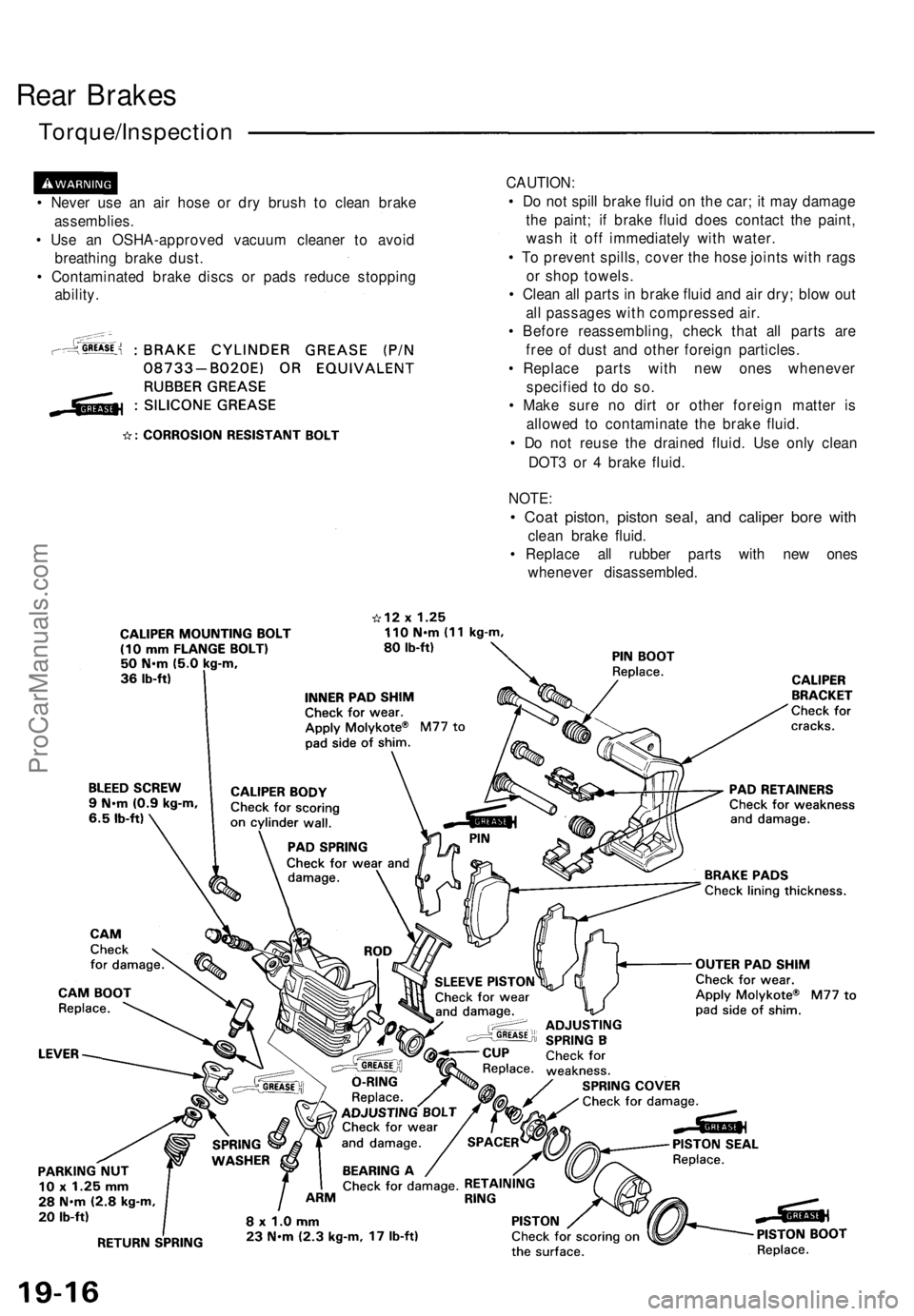
Rear Brakes
Torque/Inspection
• Never use an air hose or dry brush to clean brake
assemblies.
• Use an OSHA-approved vacuum cleaner to avoid
breathing brake dust.
• Contaminated brake discs or pads reduce stopping
ability.
CAUTION:
• Do not spill brake fluid on the car; it may damage
the paint; if brake fluid does contact the paint,
wash it off immediately with water.
• To prevent spills, cover the hose joints with rags
or shop towels.
• Clean all parts in brake fluid and air dry; blow out
all passages with compressed air.
• Before reassembling, check that all parts are
free of dust and other foreign particles.
• Replace parts with new ones whenever
specified to do so.
• Make sure no dirt or other foreign matter is
allowed to contaminate the brake fluid.
• Do not reuse the drained fluid. Use only clean
DOT3 or 4 brake fluid.
NOTE:
• Coat piston, piston seal, and caliper bore with
clean brake fluid.
• Replace all rubber parts with new ones
whenever disassembled.ProCarManuals.com
Page 505 of 1640
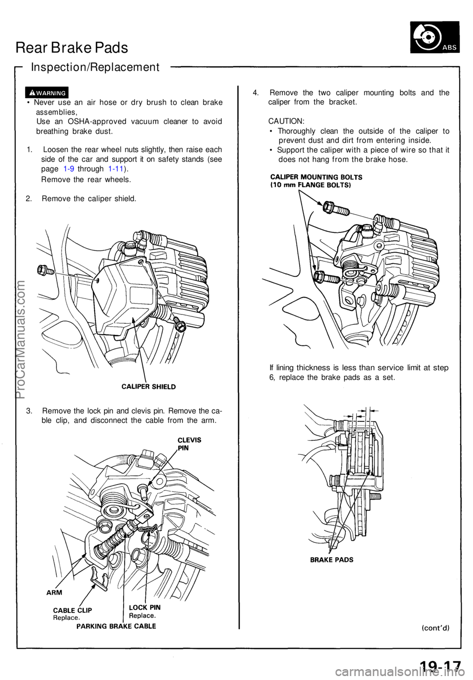
Rear Brak e Pad s
Inspection/Replacemen t
• Neve r us e a n ai r hos e o r dr y brus h t o clea n brak e
assemblies ,
Use a n OSHA-approve d vacuu m cleane r t o avoi d
breathin g brak e dust .
1 . Loose n th e rea r whee l nut s slightly , the n rais e eac h
sid e o f th e ca r an d suppor t i t o n safet y stand s (se e
pag e 1-9 throug h 1-11 ).
Remov e th e rea r wheels .
2 . Remov e th e calipe r shield .
3 . Remov e th e loc k pi n an d clevi s pin . Remov e th e ca -
bl e clip , an d disconnec t th e cabl e fro m th e arm . 4
. Remov e th e tw o calipe r mountin g bolt s an d th e
calipe r fro m th e bracket .
CAUTION :
• Thoroughl y clea n th e outsid e o f th e calipe r t o
preven t dus t an d dir t fro m enterin g inside .
• Suppor t th e calipe r wit h a piec e o f wir e s o tha t i t
doe s no t han g fro m th e brak e hose .
If linin g thicknes s i s les s tha n servic e limi t a t ste p
6, replac e th e brak e pad s a s a set .
ProCarManuals.com
Page 506 of 1640
Rear Brak e Pad s
Inspection/Replacemen t (cont'd )
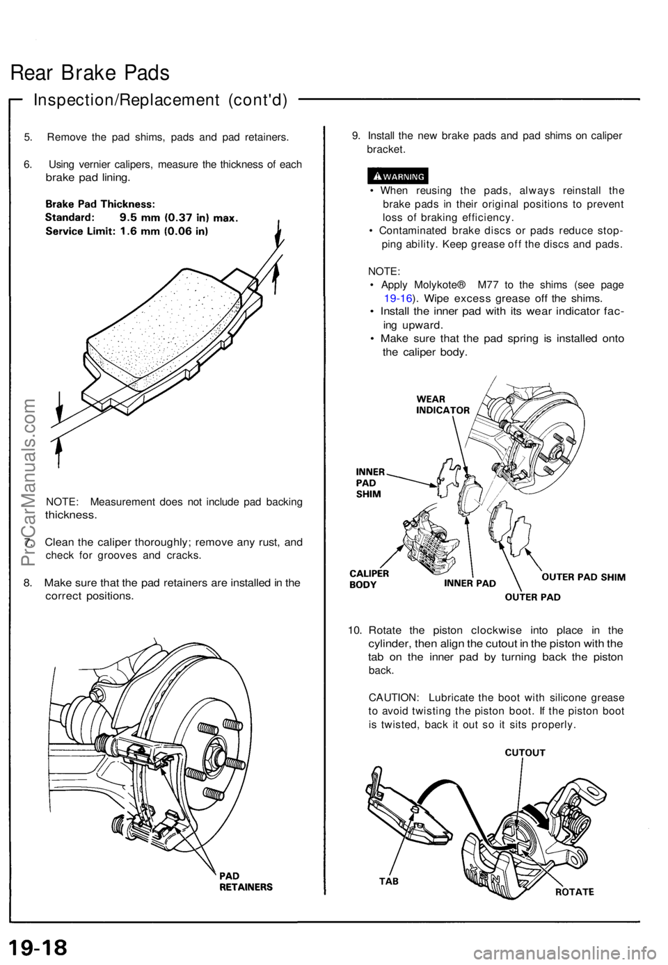
5. Remov e th e pa d shims , pad s an d pa d retainers .
6 . Usin g vernie r calipers , measur e th e thicknes s o f eac h
brak e pa d lining .
NOTE : Measuremen t doe s no t includ e pa d backin g
thickness .
7. Clea n th e calipe r thoroughly ; remov e an y rust , an d
chec k fo r groove s an d cracks .
8. Mak e sur e tha t th e pa d retainer s ar e installe d in th e
correc t positions .
9. Instal l th e ne w brak e pad s an d pa d shim s o n calipe r
bracket .
• Whe n reusin g th e pads , alway s reinstal l th e
brak e pad s i n thei r origina l position s t o preven t
los s o f brakin g efficiency .
• Contaminate d brak e disc s o r pad s reduc e stop -
pin g ability . Kee p greas e of f th e disc s an d pads .
NOTE :
• Appl y Molykote ® M7 7 t o th e shim s (se e pag e
19-16 ). Wip e exces s greas e of f th e shims .
• Instal l th e inne r pa d wit h it s wea r indicato r fac -
ing upward .
• Mak e sur e tha t th e pa d sprin g i s installe d ont o
the calipe r body .
10. Rotat e th e pisto n clockwis e int o plac e i n th e
cylinder , the n alig n th e cutou t i n th e pisto n wit h th e
tab o n th e inne r pa d b y turnin g bac k th e pisto n
back.
CAUTION : Lubricat e th e boo t wit h silicon e greas e
t o avoi d twistin g th e pisto n boot . I f th e pisto n boo t
i s twisted , bac k i t ou t s o i t sit s properly .
ProCarManuals.com
Page 507 of 1640
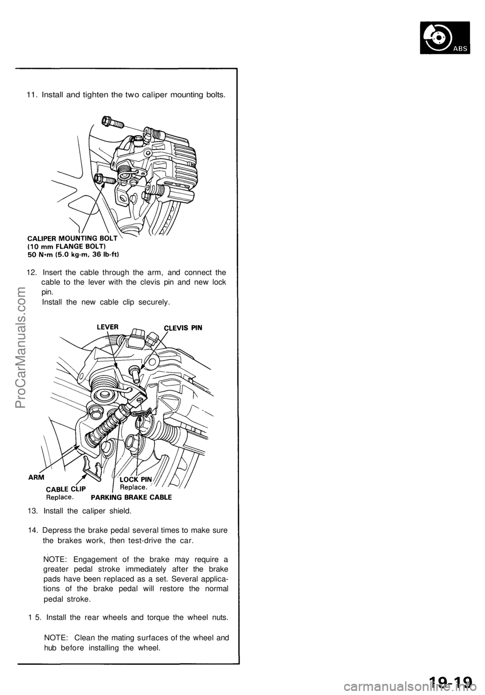
11. Install and tighten the two caliper mounting bolts.
12. Insert the cable through the arm, and connect the
cable to the lever with the clevis pin and new lock
pin.
Install the new cable clip securely.
13. Install the caliper shield.
14. Depress the brake pedal several times to make sure
the brakes work, then test-drive the car.
NOTE: Engagement of the brake may require a
greater pedal stroke immediately after the brake
pads have been replaced as a set. Several applica-
tions of the brake pedal will restore the normal
pedal stroke.
1 5. Install the rear wheels and torque the wheel nuts.
NOTE: Clean the mating surfaces of the wheel and
hub before installing the wheel.ProCarManuals.com
Page 508 of 1640
Rear Brak e Dis c
Run-Ou t Inspectio n
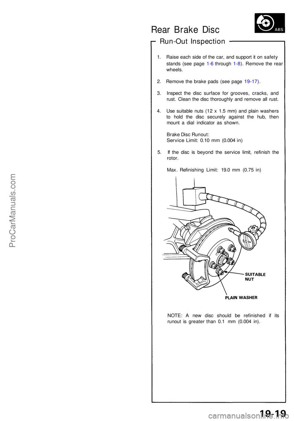
1. Rais e eac h sid e o f th e car , an d suppor t i t o n safet y
stand s (se e pag e 1- 6 throug h 1-8 ). Remov e th e rea r
wheels .
2 . Remov e th e brak e pad s (se e pag e 19-17 ).
3 . Inspec t th e dis c surfac e fo r grooves , cracks , an d
rust . Clea n th e dis c thoroughl y an d remov e al l rust .
4 . Us e suitabl e nut s (1 2 x 1. 5 mm ) an d plai n washer s
t o hol d th e dis c securel y agains t th e hub , the n
moun t a dia l indicato r a s shown .
Brak e Dis c Runout :
Service Limit : 0.1 0 m m (0.00 4 in )
5. I f th e dis c i s beyon d th e servic e limit , refinis h th e
rotor .
Max . Refinishin g Limit : 19. 0 m m (0.7 5 in )
NOTE : A ne w dis c shoul d b e refinishe d i f it s
runou t i s greate r tha n 0. 1 m m (0.00 4 in) .
ProCarManuals.com
Page 509 of 1640
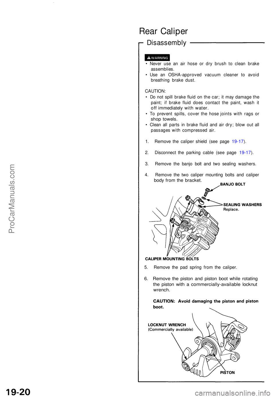
Rear Calipe r
Disassembl y
• Neve r us e a n ai r hos e o r dr y brus h t o clea n brak e
assemblies .
• Us e a n OSHA-approve d vacuu m cleane r t o avoi d
breathin g brak e dust .
CAUTION :
• D o no t spil l brak e flui d o n th e car ; i t ma y damag e th e
paint ; i f brak e flui d doe s contac t th e paint , was h i t
of f immediatel y wit h water .
• T o preven t spills , cove r th e hos e joint s wit h rag s o r
sho p towels .
• Clea n al l part s i n brak e flui d an d ai r dry ; blo w ou t al l
passage s wit h compresse d air .
1 . Remov e th e calipe r shiel d (se e pag e 19-17 ).
2 . Disconnec t th e parkin g cabl e (se e pag e 19-17 ).
3 . Remov e th e banj o bol t an d tw o sealin g washers .
4 . Remov e th e tw o calipe r mountin g bolt s an d calipe r
body fro m th e bracket .
5. Remov e th e pa d sprin g fro m th e caliper .
6. Remov e th e pisto n an d pisto n boo t whil e rotatin g
the pisto n wit h a commercially-availabl e locknu t
wrench .
ProCarManuals.com
Page 510 of 1640
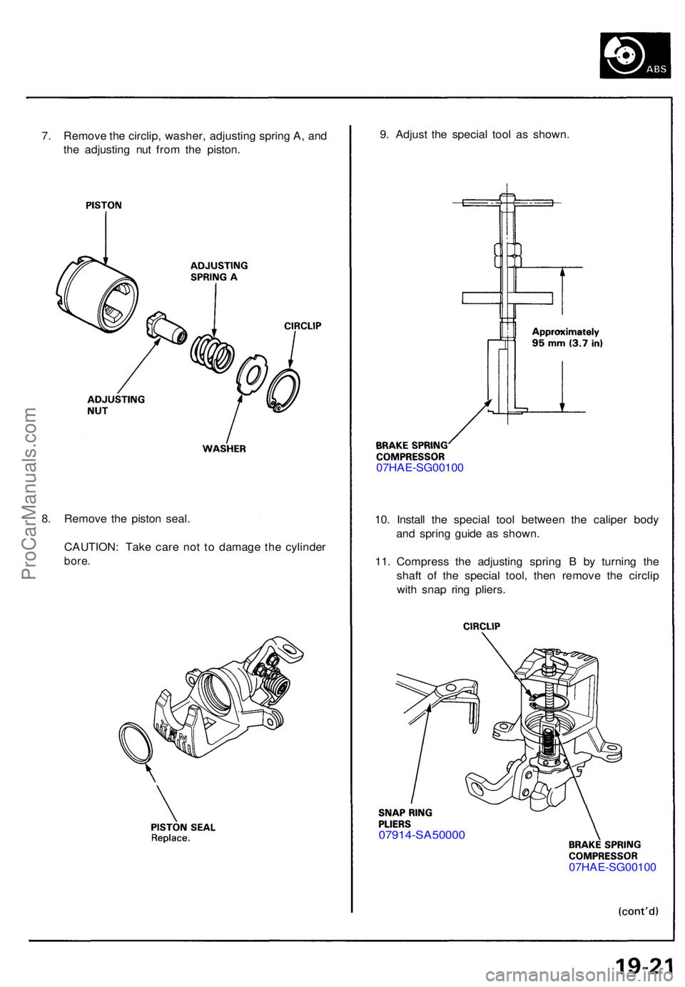
7. Remov e th e circlip , washer , adjustin g sprin g A , an d
th e adjustin g nu t fro m th e piston . 9
. Adjus t th e specia l too l a s shown .
07HAE-SG0010 0
10 . Instal l th e specia l too l betwee n th e calipe r bod y
an d sprin g guid e a s shown .
11 . Compres s th e adjustin g sprin g B by turnin g th e
shaf t o f th e specia l tool , the n remov e th e circli p
wit h sna p rin g pliers .
07914-SA5000 0
07HAE-SG0010 0
8
. Remov e th e pisto n seal .
CAUTION : Tak e car e no t t o damag e th e cylinde r
bore.
ProCarManuals.com