ACURA NSX 1991 Service Repair Manual
Manufacturer: ACURA, Model Year: 1991, Model line: NSX, Model: ACURA NSX 1991Pages: 1640, PDF Size: 60.48 MB
Page 541 of 1640
Bleeding
Air Bleedin g wit h AL B Checke r
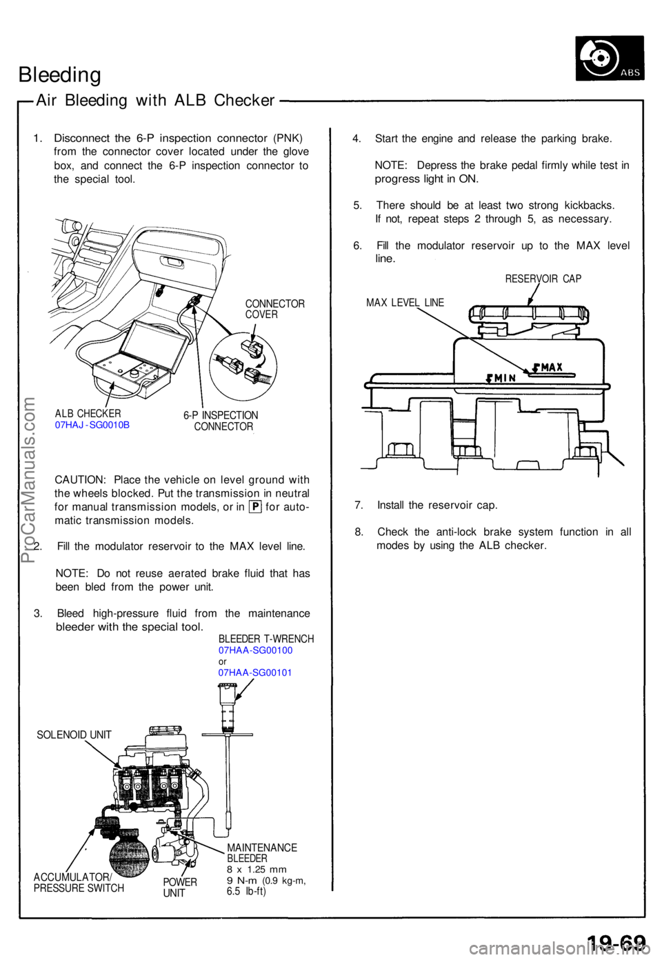
1. Disconnec t the 6- P inspection connector (PNK )
fro m th e connecto r cove r locate d unde r th e glov e
box , an d connec t th e 6- P inspectio n connecto r t o
th e specia l tool .
CONNECTO RCOVER
ALB CHECKE R07HAJ - SG0010 B 6-P INSPECTIO NCONNECTO R
CAUTION: Plac e th e vehicl e o n leve l groun d wit h
th e wheel s blocked . Pu t th e transmissio n in neutra l
for manua l transmissio n models , o r i n fo r auto -
mati c transmissio n models .
2 . Fil l th e modulato r reservoi r t o th e MA X leve l line .
NOTE : D o no t reus e aerate d brak e flui d tha t ha s
bee n ble d fro m th e powe r unit .
3 . Blee d high-pressur e flui d fro m th e maintenanc e
bleeder wit h th e specia l tool.BLEEDE R T-WRENC H07HAA-SG00100or07HAA-SG00101
SOLENOI D UNI T
ACCUMULATOR /PRESSURE SWITC HPOWERUNIT
MAINTENANC EBLEEDER8 x 1.2 5 mm9 N- m (0. 9 kg-m ,6.5 Ib-ft )
4. Star t th e engin e an d releas e th e parkin g brake .
NOTE : Depres s th e brak e peda l firml y whil e tes t i n
progres s ligh t i n ON .
5. Ther e shoul d b e a t leas t tw o stron g kickbacks .
I f not , repea t step s 2 throug h 5 , a s necessary .
6 . Fil l th e modulato r reservoi r u p t o th e MA X leve l
line.
RESERVOI R CA P
MAX LEVE L LIN E
7. Instal l th e reservoi r cap .
8 . Chec k th e anti-loc k brak e syste m functio n i n al l
mode s b y usin g th e AL B checker .
ProCarManuals.com
Page 542 of 1640
ABS Contro l Uni t
Replacemen t
SRS component s ar e locate d in thi s area . Revie w th e SR S
componen t locations , precautions , an d procedure s in th e
SR S
sectio n 2 4 befor e performin g repair s o r service .
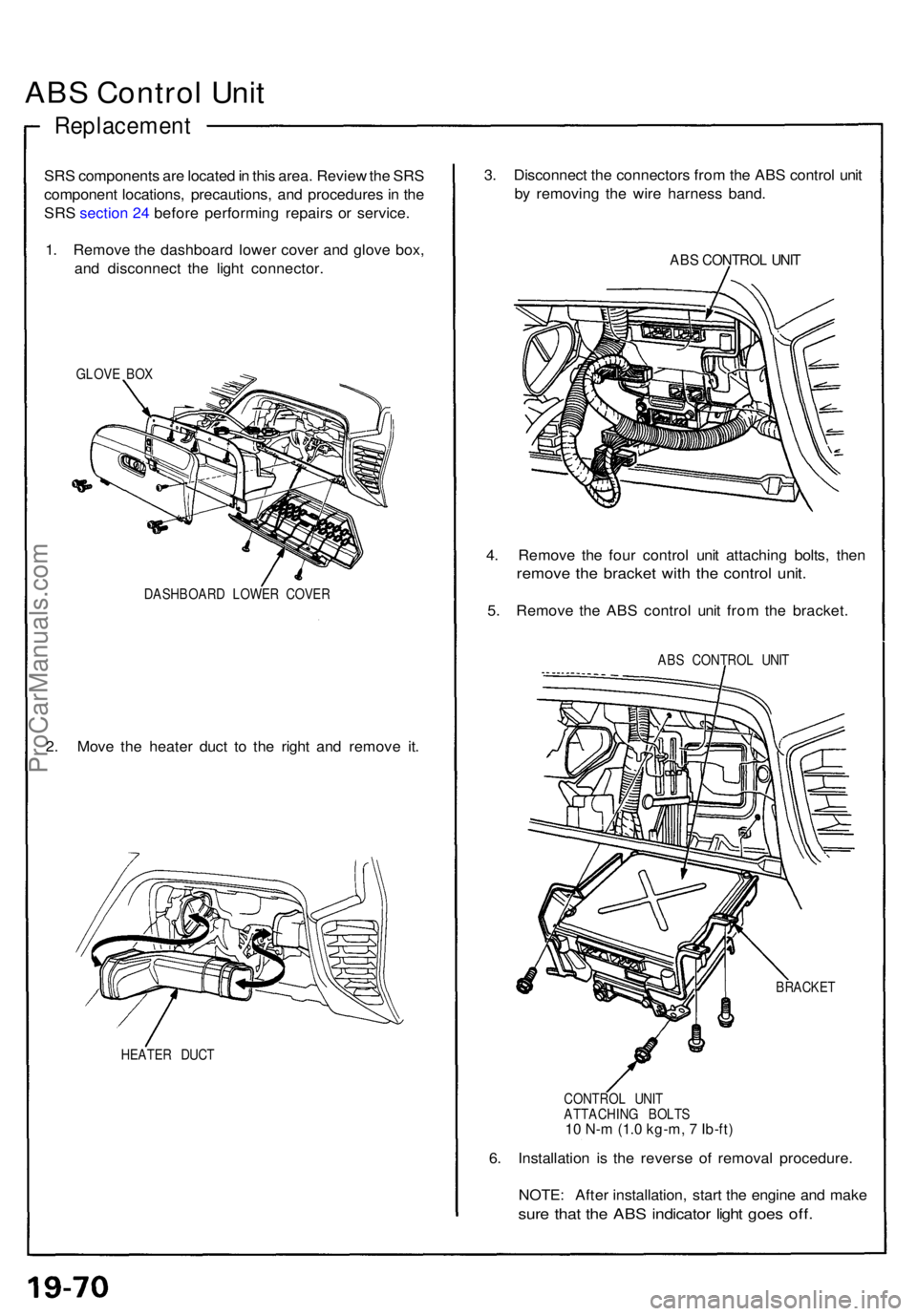
1 . Remov e th e dashboar d lowe r cove r an d glov e box ,
an d disconnec t th e ligh t connector .
GLOVE BO X
DASHBOAR D LOWE R COVE R
2. Mov e th e heate r duc t t o th e righ t an d remov e it .
HEATE R DUC T
3. Disconnec t th e connector s fro m th e AB S contro l uni t
b y removin g th e wir e harnes s band .
ABS CONTRO L UNI T
4. Remov e th e fou r contro l uni t attachin g bolts , the n
remov e th e bracke t wit h th e contro l unit .
5. Remov e th e AB S contro l uni t fro m th e bracket .
ABS CONTRO L UNI T
BRACKE T
CONTRO L UNI T
ATTACHIN G BOLT S
10 N-m (1.0 kg-m, 7 Ib-ft)
6. Installatio n i s th e revers e o f remova l procedure .
NOTE : Afte r installation , star t th e engin e an d mak e
sure tha t th e AB S indicato r ligh t goe s off .
ProCarManuals.com
Page 543 of 1640
Fail-Safe Relays/Moto r Rela y
Inspectio n
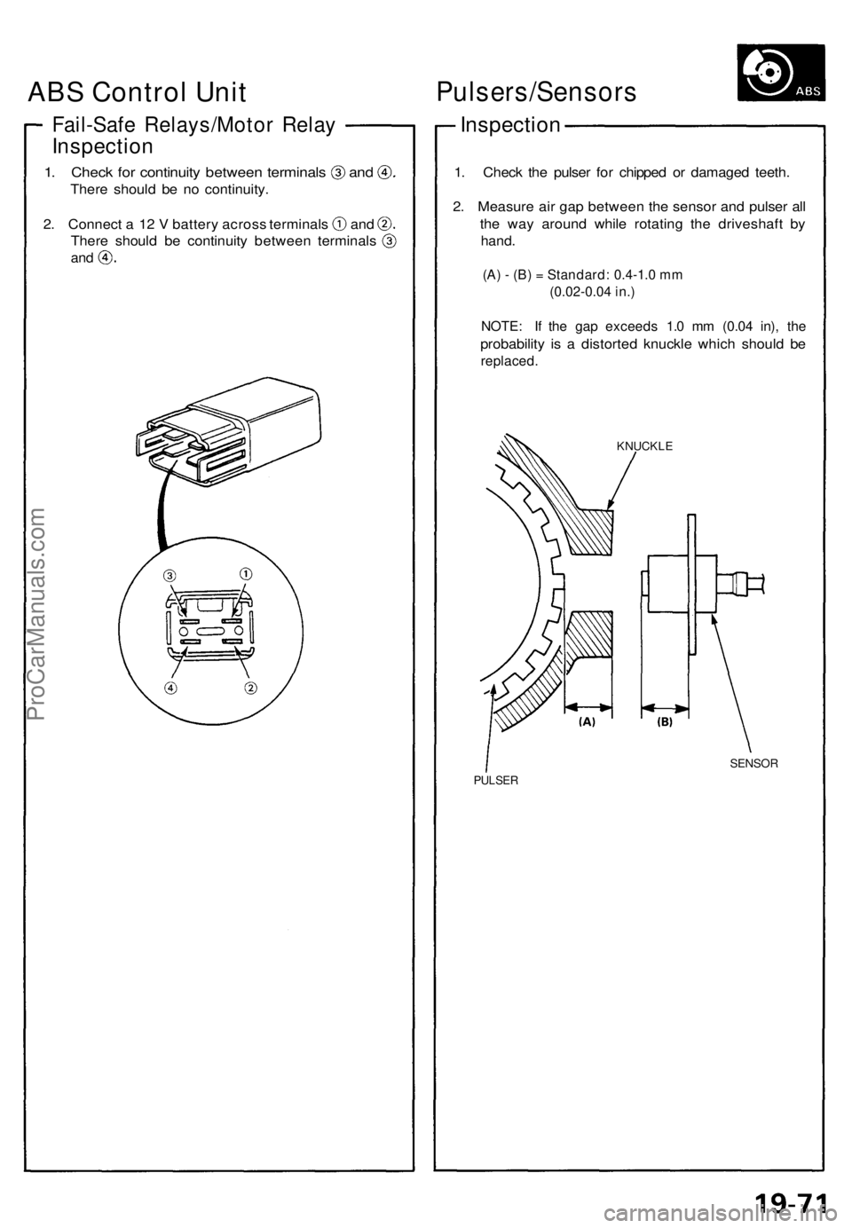
1. Chec k fo r continuit y betwee n terminal s an d
There shoul d b e n o continuity .
2. Connec t a 1 2 V batter y acros s terminal s an d
There shoul d b e continuit y betwee n terminal s
and
Pulsers/Sensor s
Inspection
1. Chec k th e pulse r fo r chippe d o r damage d teeth .
2 . Measur e ai r ga p betwee n th e senso r an d pulse r al l
th e wa y aroun d whil e rotatin g th e driveshaf t b y
hand .
(A) - (B) = Standard: 0.4-1.0 mm
(0.02-0.04 in.)
NOTE: I f th e ga p exceed s 1. 0 m m (0.0 4 in) , th e
probabilit y i s a distorte d knuckl e whic h shoul d b e
replaced .
KNUCKL E
SENSOR
PULSER
ABS Control Unit
ProCarManuals.com
Page 544 of 1640
Pulsers/Sensors
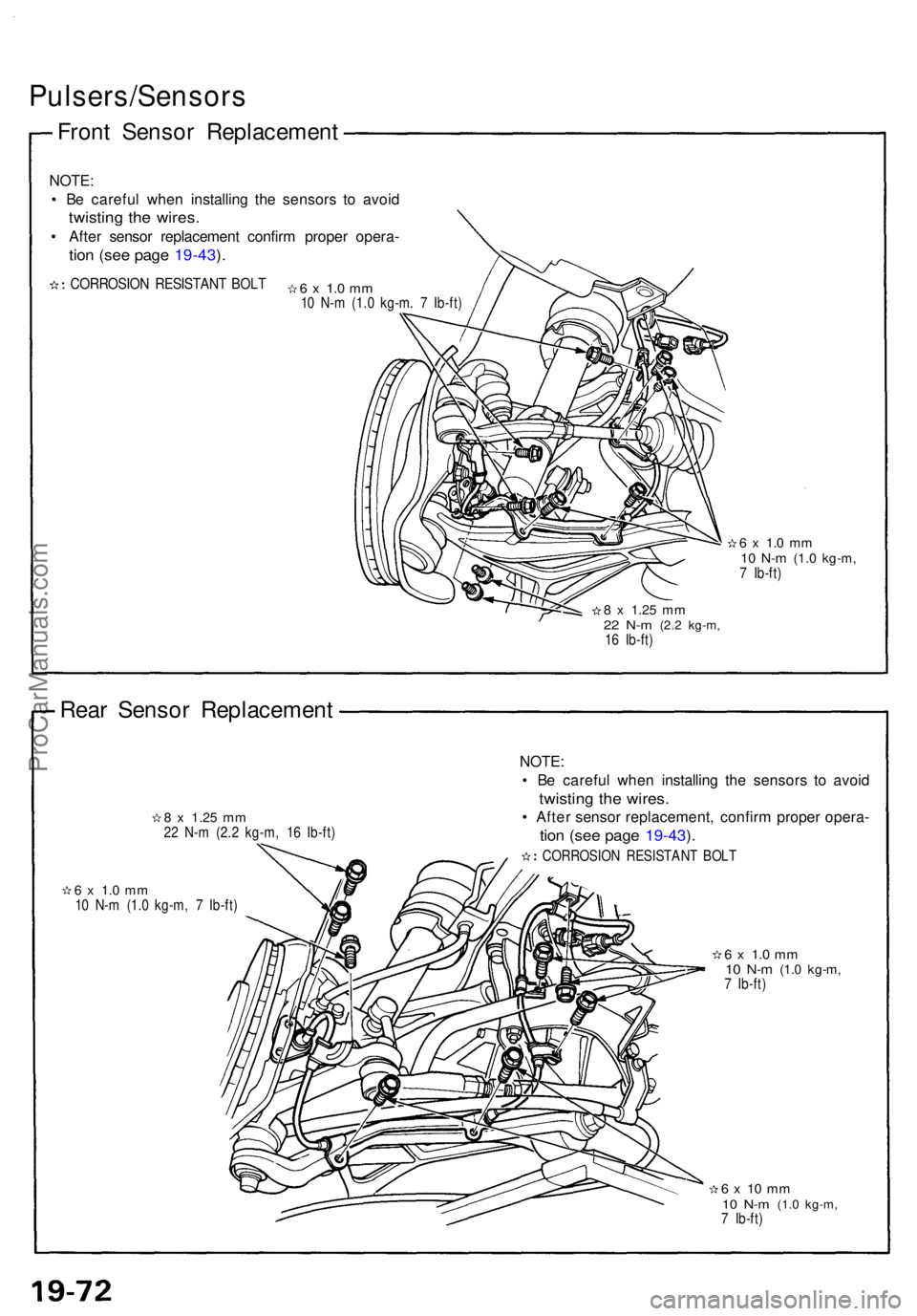
Front Senso r Replacemen t
NOTE:
• B e carefu l whe n installin g th e sensor s t o avoi d
twistin g th e wires .
• Afte r senso r replacemen t confir m prope r opera -
tion (se e pag e 19-43 ).
CORROSIO N RESISTAN T BOL T6 x 1. 0 m m10 N- m (1. 0 kg-m . 7 Ib-ft )
6 x 1. 0 m m10 N- m (1. 0 kg-m ,7 Ib-ft )
8 x 1.2 5 mm22 N- m (2. 2 kg-m ,16 Ib-ft )
Rear Senso r Replacemen t
8 x 1.2 5 mm22 N- m (2. 2 kg-m , 1 6 Ib-ft )
NOTE :
• B e carefu l whe n installin g th e sensor s t o avoi d
twistin g th e wires .
• Afte r senso r replacement , confir m prope r opera -
tion (se e pag e 19-43 ).
CORROSIO N RESISTAN T BOL T
6 x 1. 0 m m10 N- m (1. 0 kg-m , 7 Ib-ft )
6 x 1. 0 m m10 N- m (1. 0 kg-m ,7 Ib-ft )
6 x 1 0 m m10 N- m (1. 0 kg-m ,7 Ib-ft )
ProCarManuals.com
Page 545 of 1640
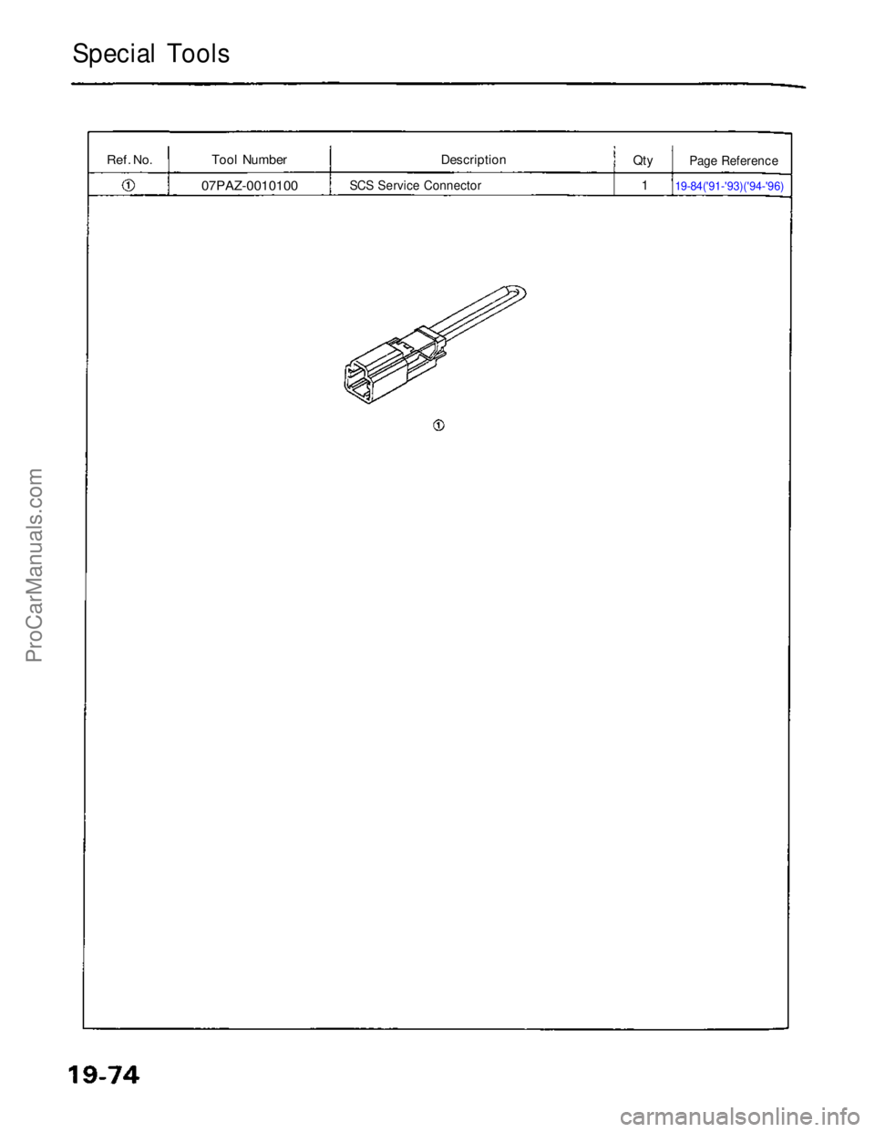
Special Tools
Ref.
No.
Tool Number
07PAZ-0010100
Description
SCS Service Connector
Qty
1
19-84('91-'93)('94-'96)Page ReferenceProCarManuals.com
Page 546 of 1640
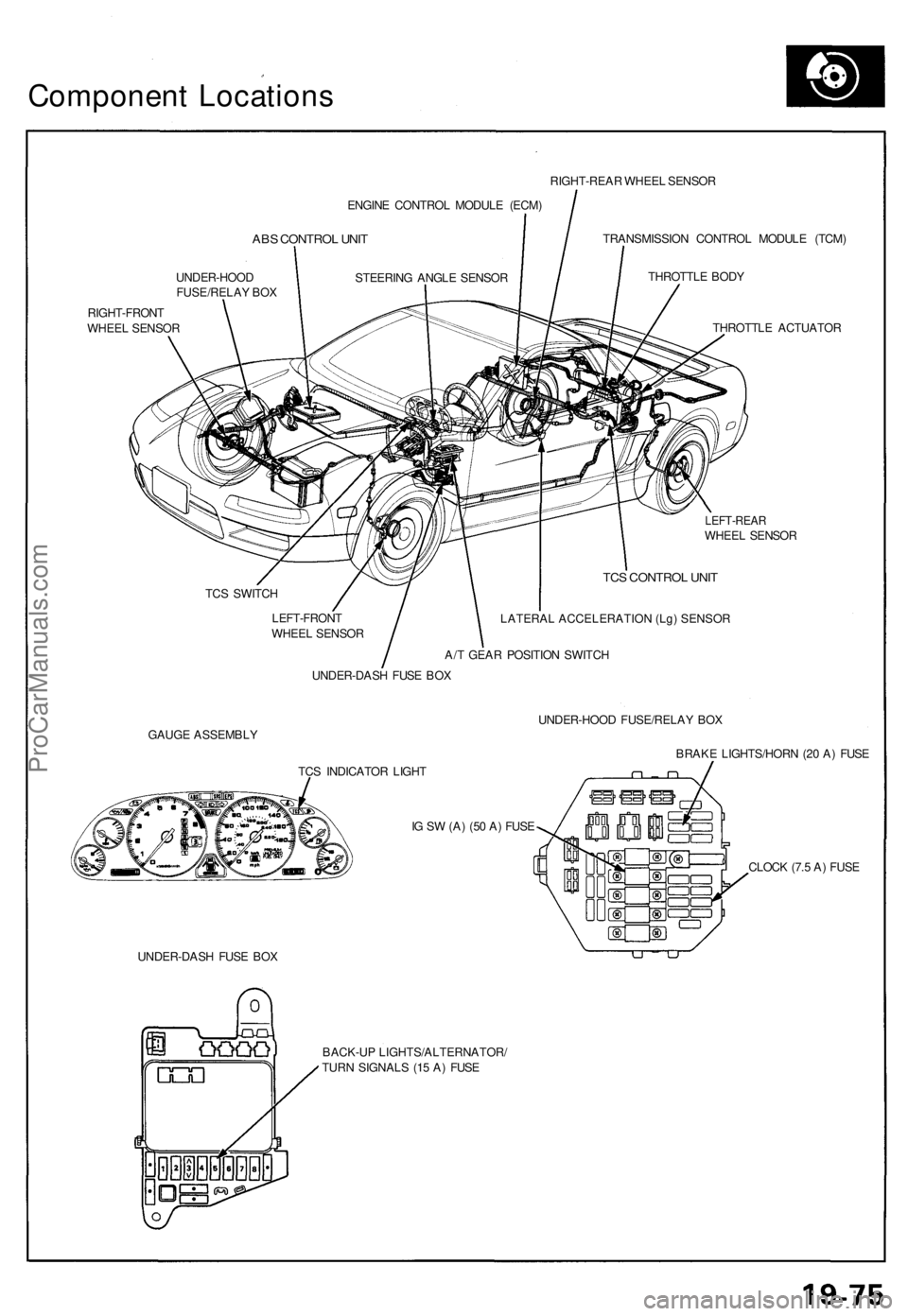
Component Location s
ENGINE CONTRO L MODUL E (ECM )
ABS CONTRO L UNI T
UNDER-HOO D
FUSE/RELA Y BO X
RIGHT-FRON T
WHEE L SENSO R RIGHT-REA
R WHEE L SENSO R
TRANSMISSIO N CONTRO L MODUL E (TCM )
THROTTL E BOD Y
THROTTL E ACTUATO R
LEFT-REARWHEEL SENSO R
TC S SWITC H
LEFT-FRON T
WHEE L SENSO R
TCS CONTRO L UNI T
LATERAL ACCELERATION (Lg) SENSOR
A/T GEA R POSITIO N SWITC H
UNDER-DAS H FUS E BO X
GAUG E ASSEMBL Y UNDER-HOO
D FUSE/RELA Y BO X
BRAK E LIGHTS/HOR N (2 0 A ) FUS E
TC S INDICATO R LIGH T
I G S W (A ) (5 0 A ) FUS E
UNDER-DAS H FUS E BO X CLOC
K (7. 5 A ) FUS E
BACK-U P LIGHTS/ALTERNATOR /
TUR N SIGNAL S (1 5 A ) FUS E
STEERIN
G ANGL E SENSO R
ProCarManuals.com
Page 547 of 1640
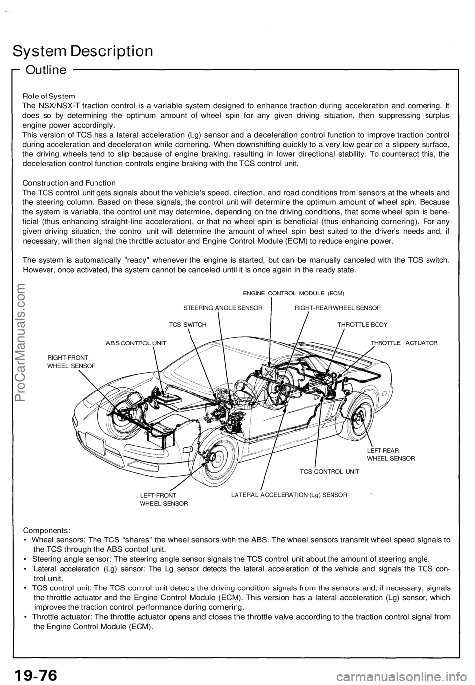
System Descriptio n
Outline
Role o f Syste m
Th e NSX/NSX- T tractio n contro l i s a variabl e syste m designe d t o enhanc e tractio n durin g acceleratio n an d cornering . I t
doe s s o b y determinin g th e optimu m amoun t o f whee l spi n fo r an y give n drivin g situation , the n suppressin g surplu s
engin e powe r accordingly .
Thi s versio n o f TC S ha s a latera l acceleratio n (Lg ) senso r an d a deceleratio n contro l functio n t o improv e tractio n contro l
durin g acceleratio n an d deceleratio n whil e cornering . Whe n downshiftin g quickl y t o a ver y lo w gea r o n a slipper y surface ,
th e drivin g wheel s ten d t o sli p becaus e o f engin e braking , resultin g i n lowe r directiona l stability . T o counterac t this , th e
deceleratio n contro l functio n control s engine braking wit h th e TC S contro l unit .
Constructio n an d Functio n
Th e TC S contro l uni t get s signal s abou t th e vehicle' s speed , direction , an d roa d condition s fro m sensor s a t th e wheel s an d
th e steerin g column . Base d o n thes e signals , th e contro l uni t wil l determin e th e optimu m amoun t o f whee l spin . Becaus e
th e syste m is variable , th e contro l uni t ma y determine , dependin g o n th e drivin g conditions , tha t som e whee l spi n i s bene -
ficia l (thu s enhancin g straight-lin e acceleration) , o r tha t n o whee l spi n i s beneficia l (thu s enhancin g cornering) . Fo r an y
give n drivin g situation , th e contro l uni t wil l determin e th e amoun t o f whee l spi n bes t suite d t o th e driver' s need s and , i f
necessary , wil l the n signa l th e throttl e actuato r an d Engin e Contro l Modul e (ECM ) t o reduc e engin e power .
Th e syste m is automaticall y "ready " wheneve r th e engin e i s started , bu t ca n b e manuall y cancele d wit h th e TC S switch .
However , onc e activated , th e syste m canno t b e cancele d unti l i t i s onc e agai n in th e read y state .
ENGIN E CONTRO L MODUL E (ECM )
STEERIN G ANGL E SENSO R
TC S SWITC H RIGHT-REA
R WHEE L SENSO R
THROTTL E BOD Y
ABS CONTRO L UNI T
RIGHT-FRON T
WHEE L SENSO R THROTTL
E ACTUATO R
LEFT-REARWHEEL SENSO R
LEFT-FRON T
WHEE L SENSO R TC
S CONTRO L UNI T
LATERAL ACCELERATION (Lg) SENSOR
Components :
• Whee l sensors : Th e TC S "shares " th e whee l sensor s wit h th e ABS . Th e whee l sensor s transmi t whee l spee d signal s t o
th e TC S throug h th e AB S contro l unit .
• Steerin g angl e sensor : Th e steerin g angl e senso r signal s th e TC S contro l uni t abou t th e amoun t o f steerin g angle .
• Latera l acceleratio n (Lg ) sensor : Th e L g senso r detect s th e latera l acceleratio n o f th e vehicl e an d signal s th e TC S con -
trol unit .
• TC S contro l unit : Th e TC S contro l uni t detect s th e drivin g conditio n signal s fro m th e sensor s and , i f necessary , signal s
th e throttl e actuato r an d th e Engin e Contro l Modul e (ECM) . Thi s versio n ha s a latera l acceleratio n (Lg ) sensor , whic h
improve s th e tractio n contro l performanc e durin g cornering .
• Throttl e actuator : Th e throttl e actuato r open s an d close s th e throttl e valv e accordin g to th e tractio n contro l signa l fro m
the Engin e Contro l Modul e (ECM) .
ProCarManuals.com
Page 548 of 1640
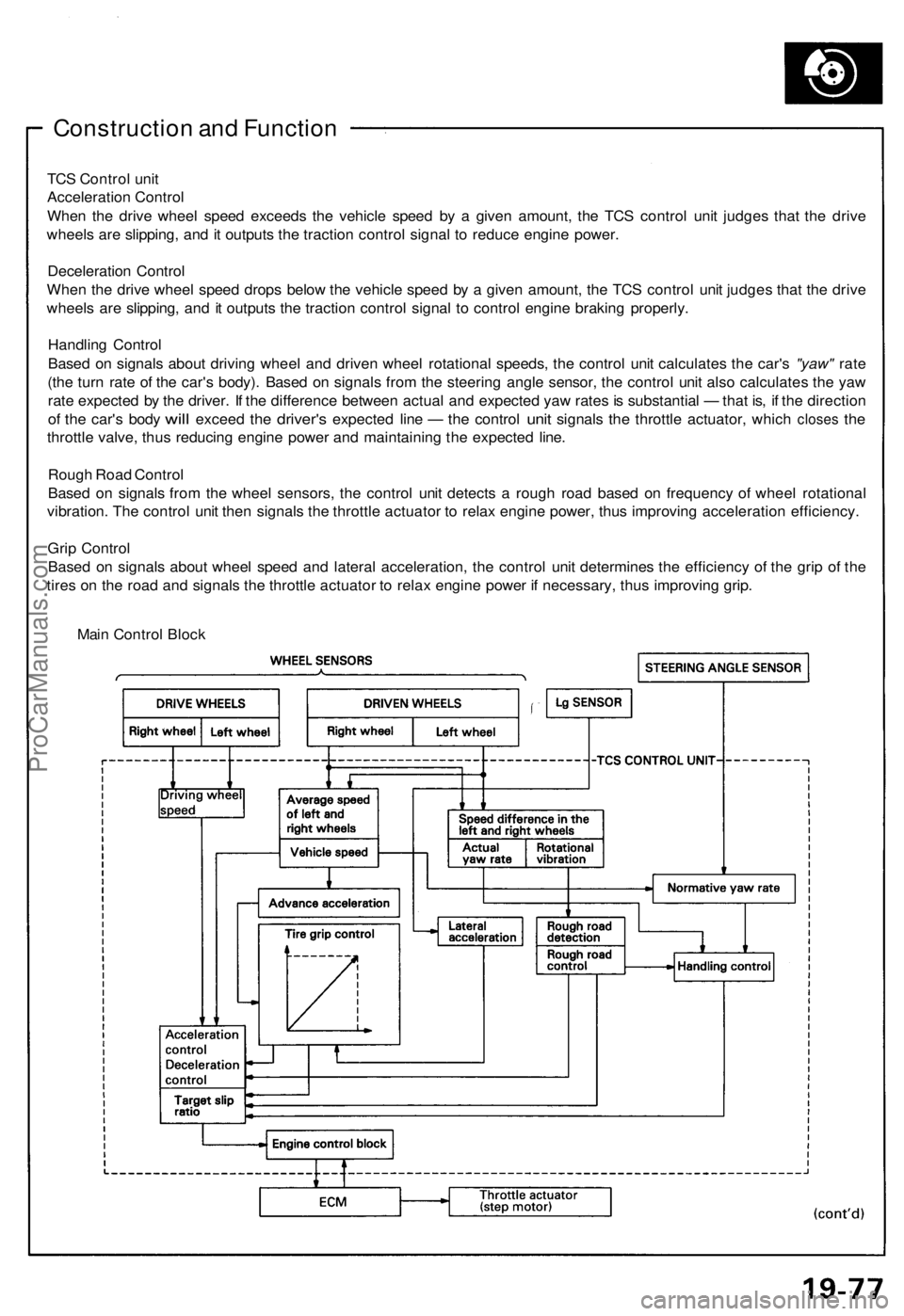
Construction an d Functio n
TCS Contro l uni t
Acceleratio n Contro l
Whe n th e driv e whee l spee d exceed s th e vehicl e spee d b y a give n amount , th e TC S contro l uni t judge s tha t th e driv e
wheel s ar e slipping , an d it output s th e tractio n contro l signa l t o reduc e engin e power .
Deceleratio n Contro l
Whe n th e driv e whee l spee d drop s belo w th e vehicl e spee d b y a give n amount , th e TC S contro l uni t judge s tha t th e driv e
wheel s ar e slipping , an d it output s th e tractio n contro l signa l t o contro l engin e brakin g properly .
Handlin g Contro l
Base d o n signal s abou t drivin g whee l an d drive n whee l rotationa l speeds , th e contro l uni t calculate s th e car' s "yaw" rate
(th e tur n rat e o f th e car' s body) . Base d o n signal s fro m th e steerin g angl e sensor , th e contro l uni t als o calculate s th e ya w
rat e expecte d b y th e driver . I f th e differenc e betwee n actua l an d expecte d ya w rate s is substantia l — tha t is , i f th e directio n
of th e car' s bod y will excee d the driver' s expecte d lin e — the contro l unit signal s the throttl e actuator , whic h close s the
throttl e valve , thu s reducin g engin e powe r an d maintainin g th e expecte d line .
Roug h Roa d Contro l
Base d o n signal s fro m th e whee l sensors , th e contro l uni t detect s a roug h roa d base d o n frequenc y o f whee l rotationa l
vibration . Th e contro l uni t the n signal s th e throttl e actuato r t o rela x engine power, thu s improvin g acceleratio n efficiency .
Gri p Contro l
Base d o n signal s abou t whee l spee d an d latera l acceleration , th e contro l uni t determine s th e efficienc y o f th e gri p o f th e
tire s o n th e roa d an d signal s th e throttl e actuato r t o rela x engine power i f necessary , thu s improvin g grip .
Mai n Contro l Bloc k
ProCarManuals.com
Page 549 of 1640
System Descriptio n
Constructio n an d Functio n
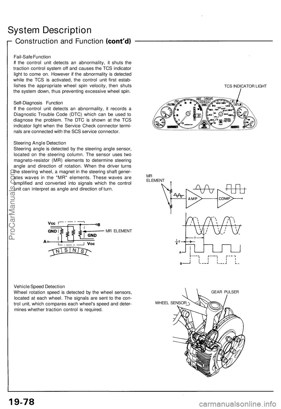
Fail-Safe Functio n
I f th e contro l uni t detect s a n abnormality , i t shut s th e
tractio n contro l syste m of f an d cause s th e TC S indicato r
ligh t t o com e on . Howeve r i f th e abnormalit y i s detecte d
whil e th e TC S i s activated , th e contro l uni t firs t estab -
lishe s th e appropriat e whee l spi n velocity , the n shut s
th e syste m down , thu s preventin g excessiv e whee l spin .
Self-Diagnosi s Functio n
I f th e contro l uni t detect s a n abnormality , i t record s a
Diagnosti c Troubl e Cod e (DTC ) whic h ca n b e use d t o
diagnos e th e problem . Th e DT C is show n a t th e TC S
indicato r ligh t whe n th e Servic e Chec k connecto r termi -
nal s ar e connecte d wit h th e SC S servic e connector .
Steerin g Angl e Detectio n
Steerin g angl e is detecte d b y th e steerin g angl e sensor ,
locate d o n th e steerin g column . Th e senso r use s tw o
magneto-resisto r (MR ) element s t o determin e steerin g
angl e an d directio n o f rotation . Whe n th e drive r turn s
th e steerin g wheel , a magne t i n th e steerin g shaf t gener -
ate s wave s i n th e "MR " elements . Thes e wave s ar e
amplifie d an d converte d int o signal s whic h th e contro l
uni t ca n interpre t a s angl e an d directio n o f turn .
MR ELEMEN T
TCS INDICATO R LIGH T
MRELEMEN T
Vehicle Spee d Detectio n
Whee l rotatio n spee d i s detecte d b y th e whee l sensors ,
locate d a t eac h wheel . Th e signal s ar e sen t t o th e con -
tro l unit , whic h compare s eac h wheel' s spee d an d deter -
mine s whethe r tractio n contro l i s required .
GEAR PULSE R
WHEEL SENSO R
ProCarManuals.com
Page 550 of 1640
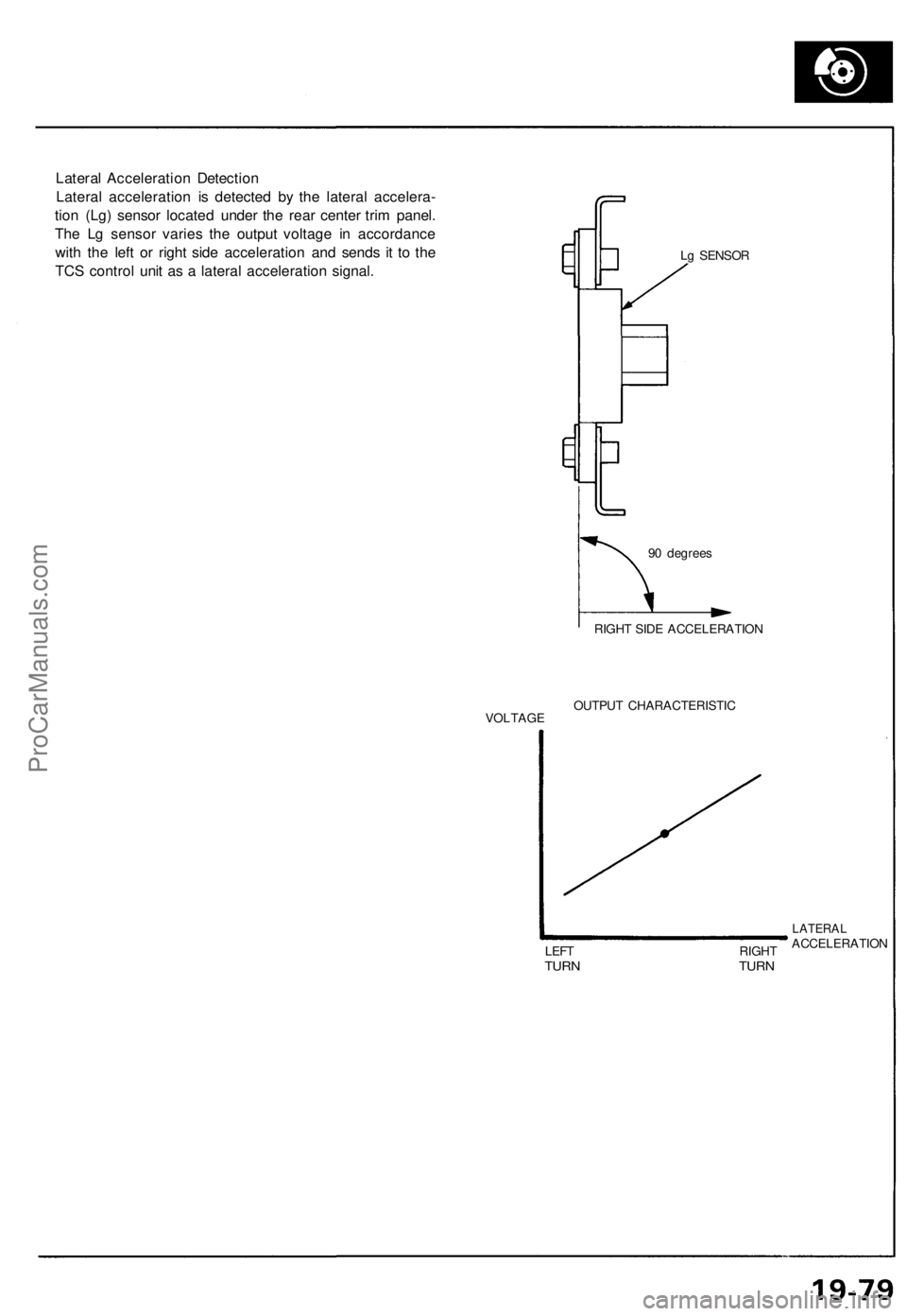
Lateral Acceleration Detection
Lateral acceleration is detected by the lateral accelera-
tion (Lg) sensor located under the rear center trim panel.
The Lg sensor varies the output voltage in accordance
with the left or right side acceleration and sends it to the
TCS control unit as a lateral acceleration signal.
Lg SENSOR
90 degrees
VOLTAGE
RIGHT SIDE ACCELERATION
OUTPUT CHARACTERISTIC
LEFT
TURN
RIGHT
TURN
LATERAL
ACCELERATIONProCarManuals.com