ACURA NSX 1991 Service Repair Manual
Manufacturer: ACURA, Model Year: 1991, Model line: NSX, Model: ACURA NSX 1991Pages: 1640, PDF Size: 60.48 MB
Page 491 of 1640
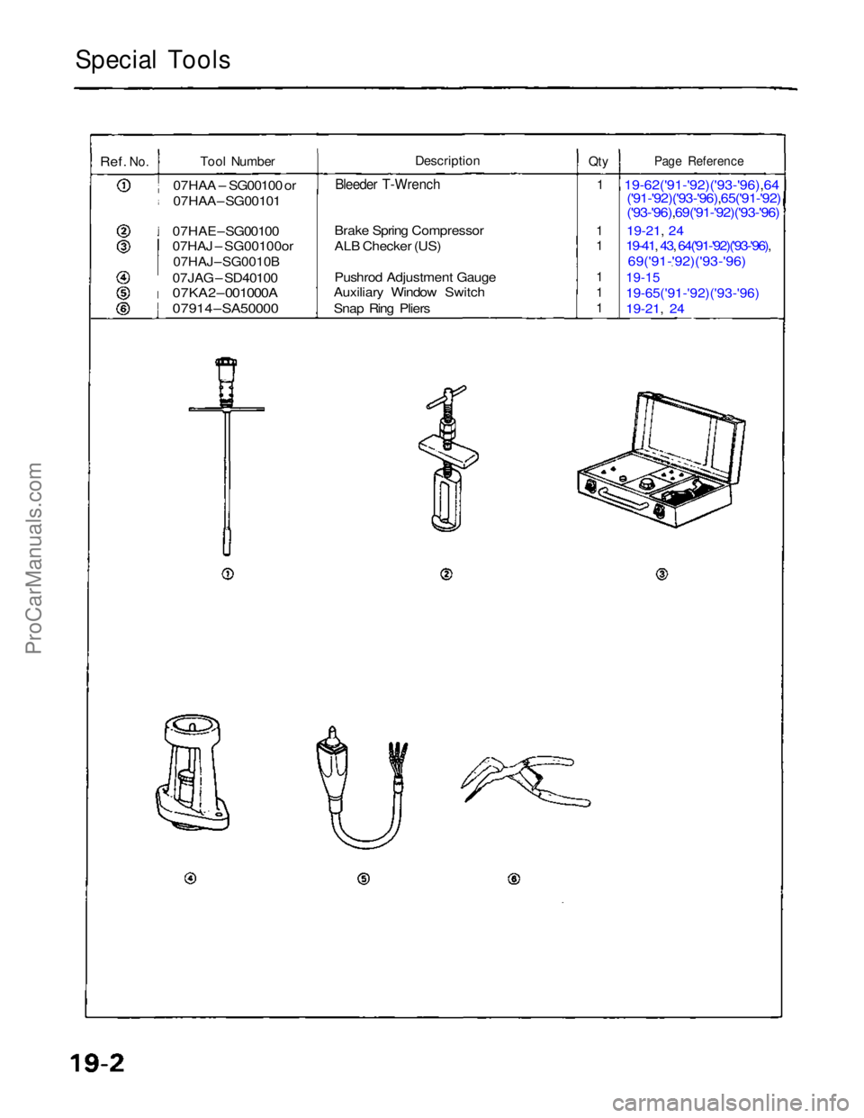
Special Tools
Ref.
No.
Tool Number
07HAA – SG00100 or
07HAA – SG00101
07HAE – SG00100
07HAJ – SG00100or
07HAJ – SG0010B
07JAG – SD40100
07KA2 – 001000A
07914 – SA50000
Description
Bleeder T-Wrench
Brake Spring Compressor
ALB Checker (US)
Pushrod Adjustment Gauge
Auxiliary Window Switch
Snap Ring Pliers
Qty
1
1
1
1
1
1
Page Reference
19-62('91-'92)('93-'96),64('91-'92)('93-'96),65('91-'92)
('93-'96),69('91-'92)('93-'96)
19-21, 24
19-41, 43, 64('91-'92)('93-'96),
69('91-'92)('93-'96)
19-15
19-65('91-'92)('93-'96)
19-21,
24
ProCarManuals.com
Page 492 of 1640
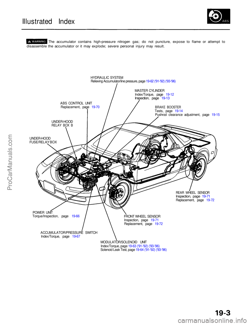
Illustrated Index
The accumulator contains high-pressure nitrogen gas; do not puncture, expose to flame or attempt to
disassemble the accumulator or it may explode; severe personal injury may result.
HYDRAULIC SYSTEM
Relieving Accumulator/line pressure, page 19-62 ('91-'92) ('93-'96)
MASTER CYLINDER
Index/Torque, page 19-12
Inspection, page 19-13
ABS CONTROL UNIT Replacement, page 19-70
BRAKE BOOSTER
Tests, page 19-14 Pushrod clearance adjustment, page 19-15
UNDER-HOOD
RELAY BOX B
UNDER-HOOD
FUSE/RELAY BOX
REAR WHEEL SENSOR
Inspection, page 19-71
Replacement, page 19-72
POWER UNIT
Torque/Inspection, page 19-66
ACCUMULATOR/PRESSURE SWITCHIndex/Torque, page 19-67 FRONT WHEEL SENSOR
Inspection, page 19-71
Replacement, page 19-72
MODULATOR/SOLENOID UNIT
Index/Torque, page 19-63 ('91-'92) ('93-'96)
Solenoid Leak Test, page 19-64 ('91-'92) ('93-'96)
ProCarManuals.com
Page 493 of 1640
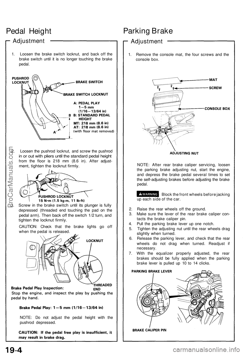
Pedal Heigh t
Adjustmen t
1. Loose n th e brak e switc h locknut , an d bac k of f th e
brak e switc h unti l i t i s n o longe r touchin g th e brak e
pedal .
2 . Loose n th e pushro d locknut , an d scre w th e pushro d
in o r ou t wit h plier s unti l th e standar d peda l heigh t
from th e floo r i s 21 8 m m (8. 6 in) . Afte r adjust -
ment, tighte n th e locknu t firmly .
3. Scre w in th e brak e switc h unti l it s plunge r i s full y
depresse d (threade d en d touchin g th e pa d o n th e
peda l arm) . The n bac k of f th e switc h 1/ 2 turn , an d
tighte n th e locknu t firmly .
CAUTION : Chec k tha t th e brak e light s g o of f
whe n th e peda l i s released .
NOTE : D o no t adjus t th e peda l heigh t wit h th e
pushro d depressed .
Parking Brak e
Adjustmen t
1. Remov e th e consol e mat , th e fou r screw s an d th e
consol e box .
NOTE : Afte r rea r brak e calipe r servicing , loose n
th e parkin g brak e adjustin g nut , star t th e engine ,
an d depres s th e brak e peda l severa l time s t o se t
the self-adjustin g brake s befor e adjustin g th e brak e
pedal .
Block th e fron t wheel s befor e jackin g
u p eac h sid e o f th e car .
2 . Rais e th e rea r wheel s of f th e ground .
3 . Mak e sur e th e leve r o f th e rea r brak e calipe r con -
tact s th e brak e calipe r pin .
4 . Pul l th e parkin g brak e leve r u p on e notch .
5 . Tighte n th e adjustin g nu t unti l th e rea r wheel s dra g
slightl y whe n turned .
6. Releas e th e parkin g lever , an d chec k tha t th e rea r
wheel s d o no t dra g whe n turned . Readjus t i f
necessary .
7. Wit h th e equalize r properl y adjusted , th e rea r
brake s shoul d b e full y applie d whe n th e parkin g
brak e leve r i s pulle d u p 1 0 t o 1 4 clicks .
ProCarManuals.com
Page 494 of 1640
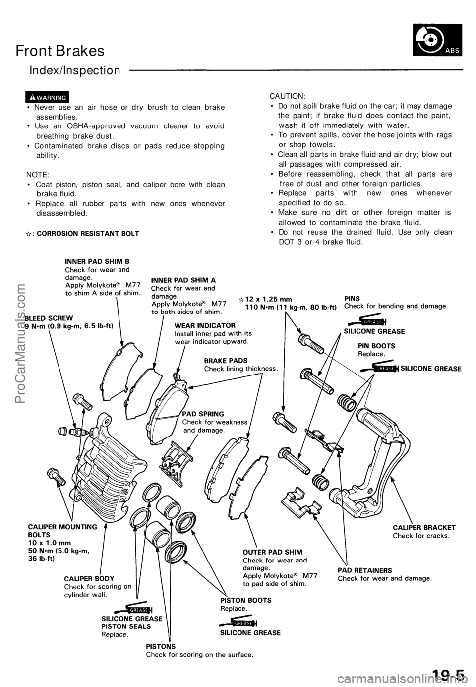
Front Brake s
Index/Inspectio n
• Neve r us e a n ai r hos e o r dr y brus h t o clea n brak e
assemblies .
• Us e a n OSHA-approve d vacuu m cleane r t o avoi d
breathin g brak e dust .
• Contaminate d brak e disc s o r pad s reduc e stoppin g
ability .
NOTE :
• Coa t piston , pisto n seal , an d calipe r bor e wit h clea n
brake fluid .
• Replac e al l rubber parts wit h ne w one s wheneve r
disassembled .
CAUTION:
• D o no t spil l brak e flui d o n th e car ; i t ma y damag e
th e paint ; i f brak e flui d doe s contac t th e paint ,
was h i t of f immediatel y wit h water .
• T o preven t spills , cove r th e hos e joint s wit h rag s
o r sho p towels .
• Clea n al l part s in brak e flui d an d ai r dry ; blo w ou t
al l passage s wit h compresse d air .
• Befor e reassembling , chec k tha t al l part s ar e
fre e o f dus t an d othe r foreig n particles .
• Replac e part s wit h ne w one s wheneve r
specifie d t o d o so .
• Mak e sur e n o dir t o r othe r foreig n matte r i s
allowe d t o contaminat e th e brak e fluid .
• D o no t reus e th e draine d fluid . Us e onl y clea n
DO T 3 o r 4 brak e fluid .
ProCarManuals.com
Page 495 of 1640
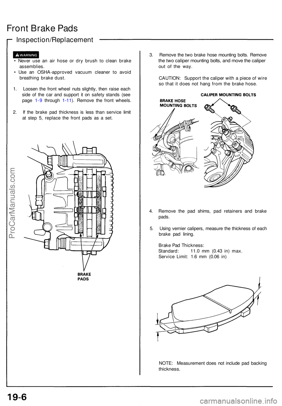
Front Brak e Pad s
Inspection/Replacemen t
• Neve r us e a n ai r hos e o r dr y brus h t o clea n brak e
assemblies .
• Us e a n OSHA-approve d vacuu m cleane r t o avoi d
breathin g brak e dust .
1 . Loose n th e fron t whee l nut s slightly , the n rais e eac h
sid e o f th e ca r an d suppor t i t o n safet y stand s (se e
pag e 1-9 throug h 1-11 ). Remov e th e fron t wheels .
2 . I f th e brak e pa d thicknes s i s les s tha n servic e limi t
a t ste p 5 , replac e th e fron t pad s a s a set . 3
. Remov e th e tw o brak e hos e mountin g bolts . Remov e
the tw o calipe r mountin g bolts , an d mov e th e calipe r
out o f th e way .
CAUTION : Suppor t th e calipe r wit h a piec e o f wir e
s o tha t i t doe s no t han g fro m th e brak e hose .
4 . Remov e th e pa d shims , pa d retainer s an d brak e
pads .
5 . Usin g vernie r calipers , measur e th e thicknes s o f eac h
brak e pa d lining .
Brak e Pa d Thickness :
Standard : 11. 0 m m (0.4 3 in ) max .
Servic e Limit : 1. 6 m m (0.0 6 in )
NOTE : Measuremen t doe s no t includ e pa d backin g
thickness .
ProCarManuals.com
Page 496 of 1640
6. Clea n th e calipe r thoroughly ; remov e an y rust , an d
chec k fo r groove s an d cracks .
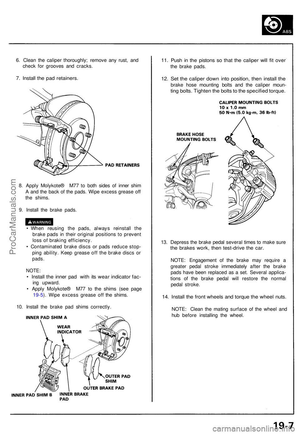
7. Instal l th e pa d retainers .
11. Pus h i n th e piston s s o tha t th e calipe r wil l fi t ove r
the brak e pads .
12. Se t th e calipe r dow n int o position , the n instal l th e
brak e hos e mountin g bolt s an d th e calipe r moun -
ting bolts . Tighte n th e bolt s to th e specifie d torque .
8. Appl y Molykote ® M7 7 t o bot h side s o f inne r shi m
A an d th e bac k o f th e pads . Wip e exces s greas e of f
th e shims .
9 . Instal l th e brak e pads .
• Whe n reusin g th e pads , alway s reinstal l th e
brak e pad s i n thei r origina l position s t o preven t
los s o f brakin g efficiency .
• Contaminate d brak e disc s o r pad s reduc e stop -
pin g ability . Kee p greas e of f th e brak e disc s o r
pads .
NOTE :
• Instal l th e inne r pa d wit h it s wea r indicato r fac -
ing upward .
• Appl y Molykote ® M7 7 t o th e shim s (se e pag e
19-5 ). Wip e exces s greas e of f th e shims .
10 . Instal l th e brak e pa d shim s correctly . 13
. Depres s th e brak e peda l severa l time s t o mak e sur e
the brake s work , the n test-driv e th e car .
NOTE : Engagemen t of the brak e ma y requir e a
greate r peda l strok e immediatel y afte r th e brak e
pad s hav e bee n replace d a s a set . Severa l applica -
tion s of the brak e peda l wil l restor e th e norma l
peda l stroke .
14. Instal l th e fron t wheel s an d torqu e th e whee l nuts .
NOTE : Clea n th e matin g surfac e o f th e whee l an d
hu b befor e installin g th e wheel .
ProCarManuals.com
Page 497 of 1640
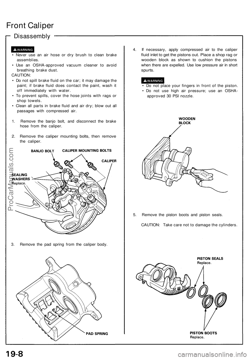
Front Calipe r
Disassembl y
• Neve r us e a n ai r hos e o r dr y brus h t o clea n brak e
assemblies .
• Us e a n OSHA-approve d vacuu m cleane r t o avoi d
breathin g brak e dust .
CAUTION :
• D o no t spil l brak e flui d o n th e car ; i t ma y damag e th e
paint ; i f brak e flui d doe s contac t th e paint , was h i t
of f immediatel y wit h water .
• T o preven t spills , cove r th e hos e joint s wit h rag s o r
sho p towels .
• Clea n al l part s i n brak e flui d an d ai r dry ; blo w ou t al l
passage s wit h compresse d air .
1 . Remov e th e banj o bolt , an d disconnec t th e brak e
hos e fro m th e caliper .
2. Remov e th e calipe r mountin g bolts , the n remov e
the caliper .
3 . Remov e th e pa d sprin g fro m th e calipe r body . 4
. I f necessary , appl y compresse d ai r t o th e calipe r
fluid inle t t o ge t th e piston s out . Plac e a sho p ra g o r
woode n bloc k a s show n t o cushio n th e piston s
when ther e ar e expelled . Us e lo w pressur e ai r i n shor t
spurts .
• D o no t plac e you r finger s i n fron t o f th e piston .
• D o no t us e hig h ai r pressure ; us e a n OSHA -
approve d 3 0 PS I nozzle .
5 . Remov e th e pisto n boot s an d pisto n seals .
CAUTION : Tak e car e no t t o damag e th e cylinders .
ProCarManuals.com
Page 498 of 1640
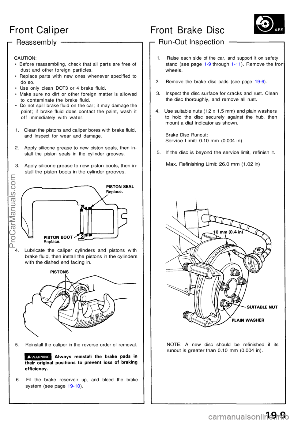
Reassembly
CAUTION:
• Befor e reassembling , chec k tha t al l part s ar e fre e o f
dus t an d othe r foreig n particles .
• Replac e part s wit h ne w one s wheneve r specifie d t o
do so .
• Us e onl y clea n DOT 3 o r 4 brak e fluid .
• Mak e sur e n o dir t o r othe r foreig n matte r i s allowe d
t o contaminat e th e brak e fluid .
• D o no t spil l brak e flui d o n th e car ; i t ma y damag e th e
paint ; i f brak e flui d doe s contac t th e paint , was h i t
of f immediatel y wit h water .
1. Clea n th e piston s an d calipe r bore s wit h brak e fluid ,
and inspec t fo r wea r an d damage .
2. Appl y silicon e greas e t o ne w pisto n seals , the n in -
stal l th e pisto n seal s i n th e cylinde r grooves .
3. Appl y silicon e greas e t o ne w pisto n boots , the n in -
stal l th e pisto n boot s in th e cylinde r grooves .
4. Lubricat e th e calipe r cylinder s an d piston s wit h
brak e fluid , the n instal l th e piston s i n th e cylinder s
with th e dishe d en d facin g in .
5. Reinstal l th e calipe r i n th e revers e orde r o f removal .
6 . Fil l th e brak e reservoi r up , an d blee d th e brak e
system (se e pag e 19-10 ).
NOTE : A ne w dis c shoul d b e refinishe d i f it s
runou t i s greate r tha n 0.1 0 m m (0.00 4 in) .
Fron t Brak e Dis c
Run-Ou t Inspectio n
1. Rais e eac h sid e o f th e car , an d suppor t i t o n safet y
stand (se e pag e 1-9 throug h 1-11 ). Remov e th e fron t
wheels .
2. Remov e th e brak e dis c pad s (se e pag e 19-6 ).
3 . Inspec t th e dis c surfac e fo r crack s an d rust . Clea n
the dis c thoroughly , an d remov e al l rust .
4. Us e suitabl e nut s (1 2 x 1. 5 mm ) an d plai n washer s
to hol d th e dis c securel y agains t th e hub , the n
moun t a dia l indicato r a s shown .
Brake Dis c Runout :
Service Limit : 0.1 0 m m (0.00 4 in )
5. I f th e dis c i s beyon d th e servic e limit , refinis h it .
Max . Refinishin g Limit : 26. 0 m m (1.0 2 in )
Front Caliper
ProCarManuals.com
Page 499 of 1640
Front Brak e Dis c
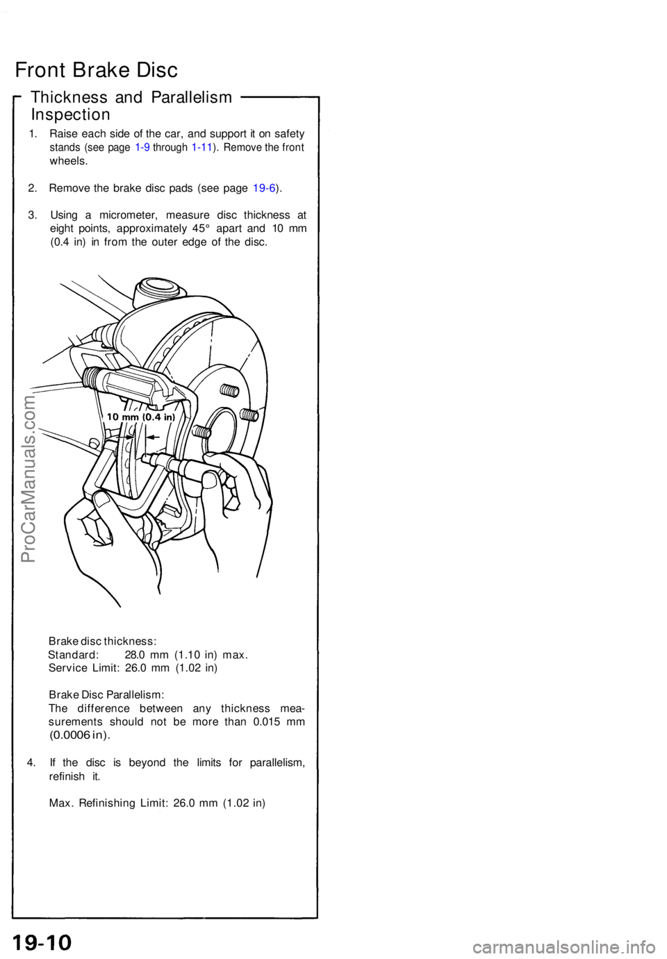
Thicknes s an d Parallelis m
Inspectio n
1. Rais e eac h sid e o f th e car , an d suppor t i t o n safet y
stands (se e pag e 1-9 throug h 1-11 ). Remov e th e fron t
wheels .
2 . Remov e th e brak e dis c pad s (se e pag e 19-6 ).
3 . Usin g a micrometer , measur e dis c thicknes s a t
eigh t points , approximatel y 45 ° apar t an d 1 0 m m
(0. 4 in ) i n fro m th e oute r edg e o f th e disc .
Brak e dis c thickness :
Standard : 28. 0 m m (1.1 0 in ) max .
Servic e Limit : 26. 0 m m (1.0 2 in )
Brak e Dis c Parallelism :
Th e differenc e betwee n an y thicknes s mea -
surement s shoul d no t b e mor e tha n 0.01 5 m m
(0.000 6 in) .
4. I f th e dis c i s beyon d th e limit s fo r parallelism ,
refinis h it .
Max . Refinishin g Limit : 26.0 mm (1.0 2 in )
ProCarManuals.com
Page 500 of 1640
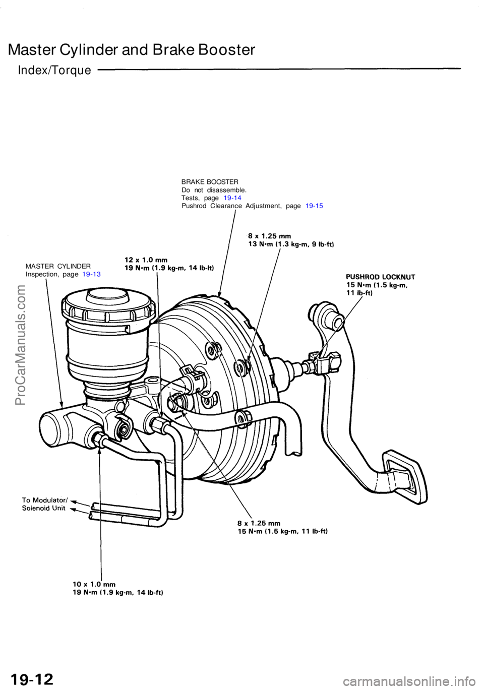
Master Cylinde r an d Brak e Booste r
Index/Torqu e
BRAKE BOOSTE R
D o no t disassemble .
Tests , pag e 19-1 4
Pushro d Clearanc e Adjustment , pag e 19-1 5
MASTE R CYLINDE R
Inspection, pag e 19-1 3
ProCarManuals.com