ACURA NSX 1997 Service Repair Manual
Manufacturer: ACURA, Model Year: 1997,
Model line: NSX,
Model: ACURA NSX 1997
Pages: 1503, PDF Size: 57.08 MB
ACURA NSX 1997 Service Repair Manual
NSX 1997
ACURA
ACURA
https://www.carmanualsonline.info/img/32/56989/w960_56989-0.png
ACURA NSX 1997 Service Repair Manual
Trending: hood release, key battery, lock, seat adjustment, air condition, phone, wheel bolt torque
Page 1121 of 1503
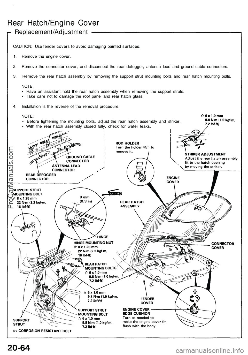
Rear Hatch/Engine Cover
Replacement/Adjustment
CAUTION: Use fender covers to avoid damaging painted surfaces.
1. Remove the engine cover.
2. Remove the connector cover, and disconnect the rear defogger, antenna lead and ground cable connectors.
3. Remove the rear hatch assembly by removing the support strut mounting bolts and rear hatch mounting bolts.
NOTE:
• Have an assistant hold the rear hatch assembly when removing the support struts.
• Take care not to damage the roof panel and rear hatch glass.
4. Installation is the reverse of the removal procedure.
NOTE:
• Before tightening the mounting bolts, adjust the rear hatch assembly and striker.
• With the rear hatch assembly closed fully, check for water leaks.ProCarManuals.com
Page 1122 of 1503
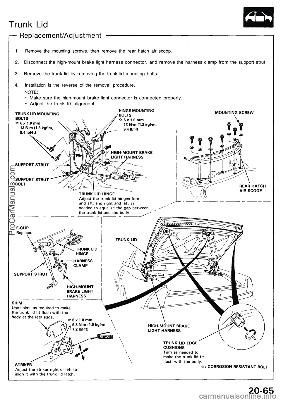
Trunk Lid
Replacement/Adjustment
1. Remove the mounting screws, then remove the rear hatch air scoop.
2. Disconnect the high-mount brake light harness connector, and remove the harness clamp from the support strut.
3. Remove the trunk lid by removing the trunk lid mounting bolts.
4. Installation is the reverse of the removal procedure.
NOTE:
• Make sure the high-mount brake light connector is connected properly.
• Adjust the trunk lid alignment.ProCarManuals.com
Page 1123 of 1503
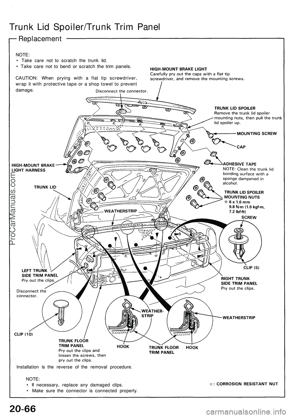
Trunk Lid Spoiler/Trunk Trim Panel
Replacement
NOTE:
• Take care not to scratch the trunk lid.
• Take care not to bend or scratch the trim panels.
CAUTION: When prying with a flat tip screwdriver,
wrap it with protective tape or a shop towel to prevent
damage.
Installation is the reverse of the removal procedure.
NOTE:
• If necessary, replace any damaged clips.
• Make sure the connector is connected properly.ProCarManuals.com
Page 1124 of 1503
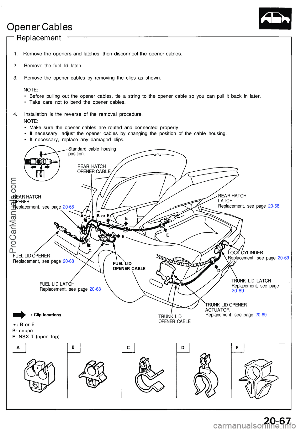
Opener Cable s
Replacemen t
1. Remov e th e opener s an d latches , the n disconnec t th e opene r cables .
2. Remov e th e fue l li d latch .
3 . Remov e th e opene r cable s b y removin g th e clip s a s shown .
NOTE:
• Befor e pullin g ou t th e opene r cables , ti e a strin g t o th e opene r cabl e s o yo u ca n pul l i t bac k i n later .
• Tak e car e no t t o ben d th e opene r cables .
4 . Installatio n i s th e revers e o f th e remova l procedure .
NOTE:
• Mak e sur e th e opene r cable s ar e route d an d connecte d properly .
• I f necessary , adjus t th e opene r cable s b y changin g th e positio n o f th e cabl e housing .
• I f necessary , replac e an y damage d clips .
Standar d cabl e housin g
position .
REA R HATC H
OPENE R CABL E
REAR HATC H
LATCHReplacement , se e pag e 20-6 8
REA
R HATC HOPENE RReplacement , se e pag e 20-6 8
FUE L LI D OPENE R
Replacement , se e pag e 20-6 8
FUE L LI D LATC H
Replacement , se e pag e 20-6 8 LOC
K CYLINDE R
Replacement , se e pag e 20-6 9
TRUN K LI D LATC H
Replacement , se e pag e
20-69
TRUN K LI DOPENE R CABL E
TRUNK LI D OPENE RACTUATO RReplacement , se e pag e 20-6 9
ProCarManuals.com
Page 1125 of 1503
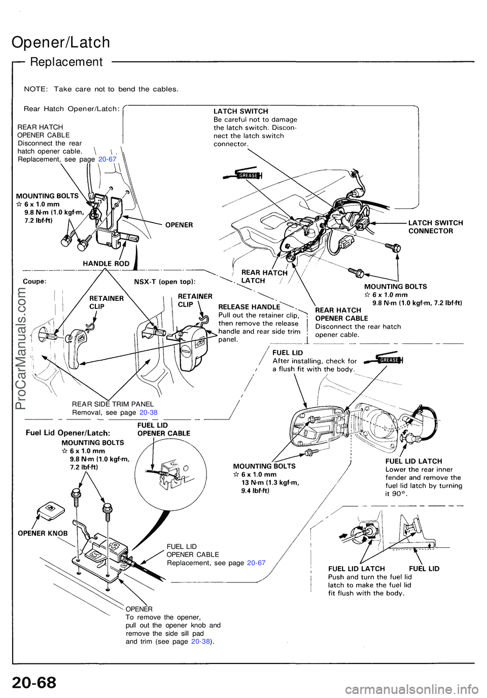
Opener/Latch
Replacement
NOTE: Tak e car e no t t o ben d th e cables .
Rear Hatc h Opener/Latch :
REAR SID E TRI M PANE L
Removal , se e pag e 20-3 8
FUE L LI D
OPENE R CABL EReplacement , se e pag e 20-6 7
OPENE RTo remov e th e opener ,
pul l ou t th e opene r kno b an d
remov e th e sid e sil l pa d
an d tri m (se e pag e 20-38 ).
REA
R HATC H
OPENE R CABL EDisconnec t th e rea r
hatc h opene r cable .
Replacement , se e pag e 20-6 7
ProCarManuals.com
Page 1126 of 1503
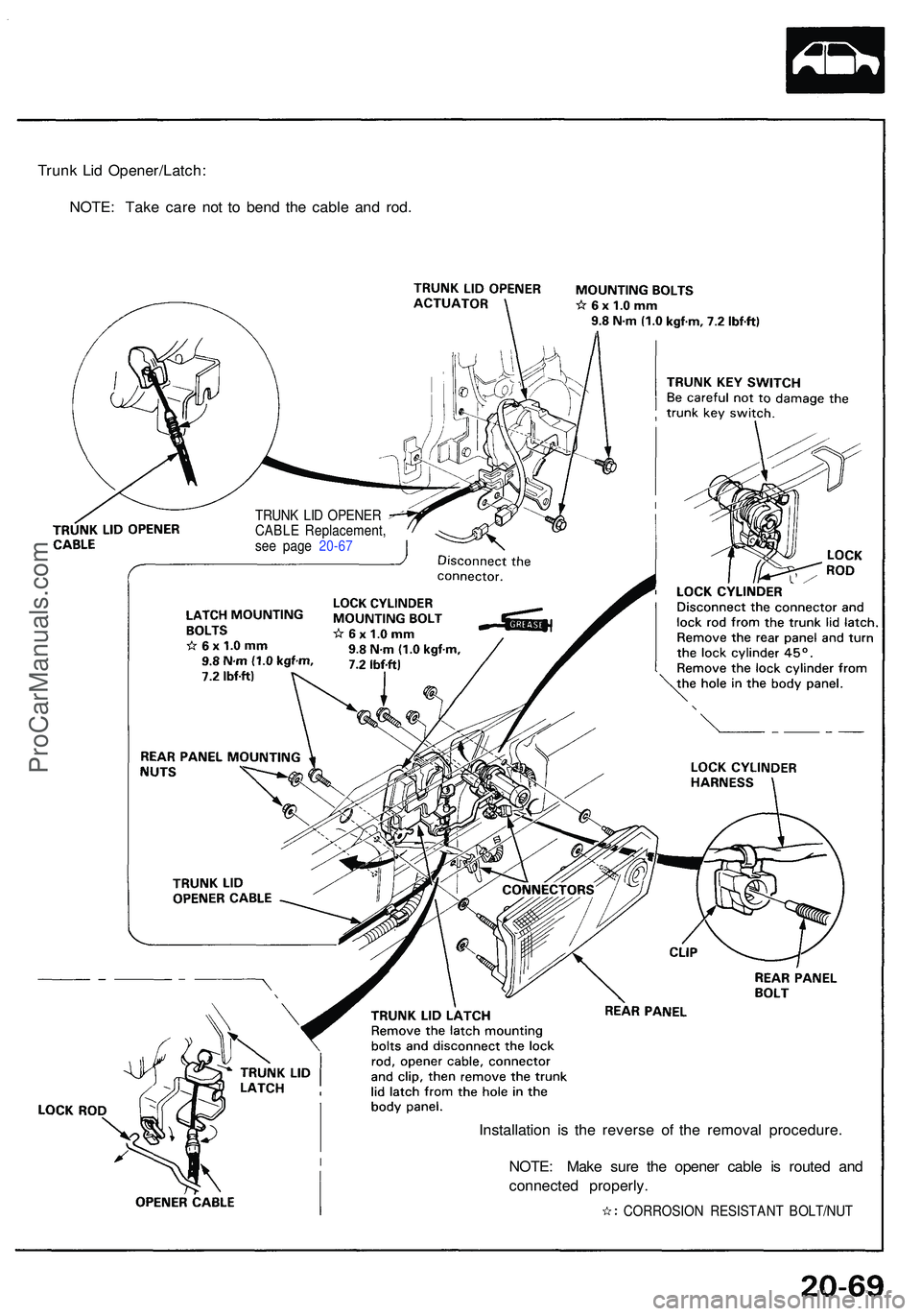
Trunk Li d Opener/Latch :
NOTE : Tak e car e no t t o ben d th e cabl e an d rod .
Installation i s th e revers e o f th e remova l procedure .
NOTE : Mak e sur e th e opene r cabl e i s route d an d
connecte d properly .
TRUNK LI D OPENE R
CABL E Replacement ,
se e pag e 20-6 7
CORROSION RESISTAN T BOLT/NU T
ProCarManuals.com
Page 1127 of 1503
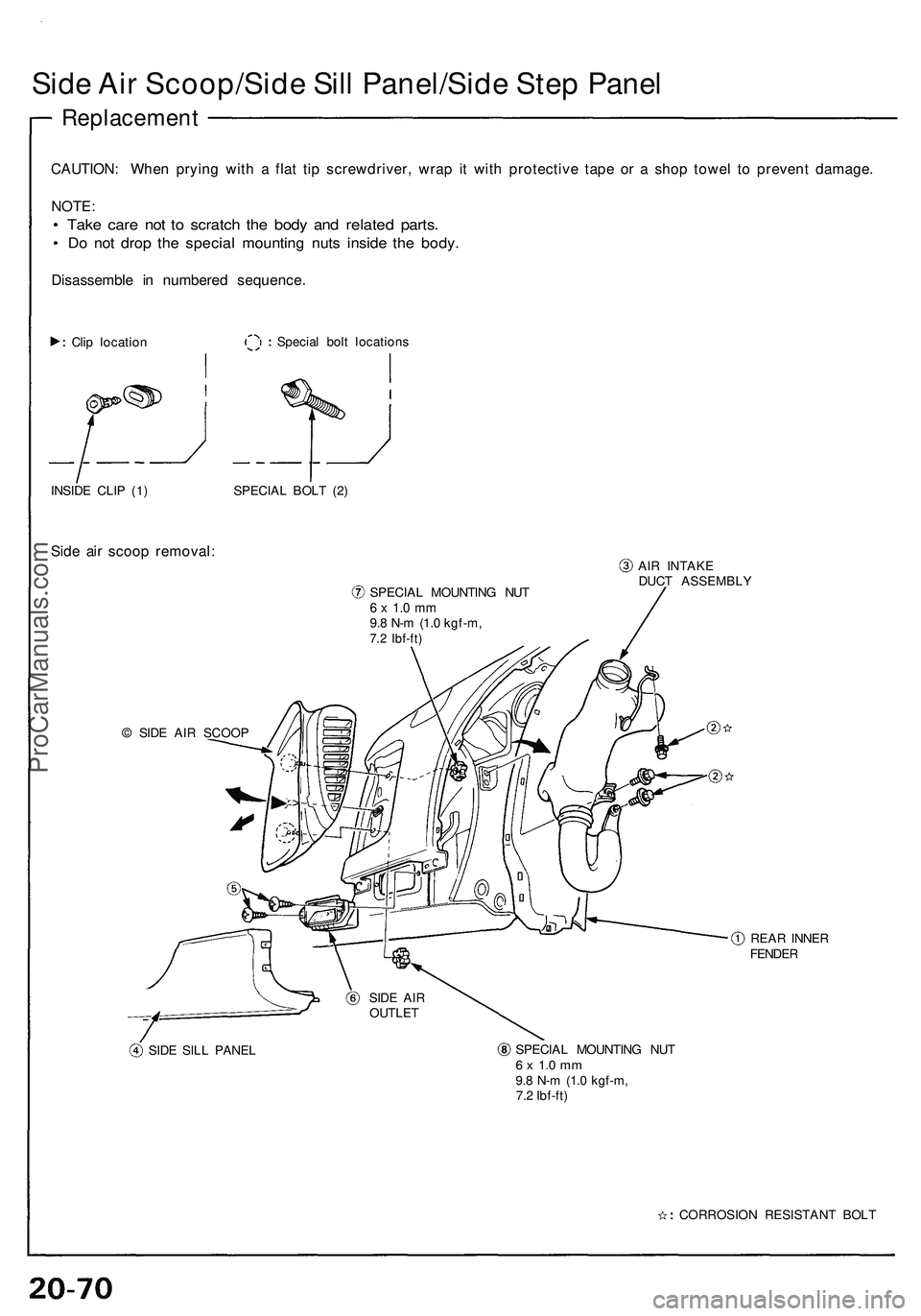
Side Air Scoop/Side Sill Panel/Side Step Panel
Replacement
CAUTION: When prying with a flat tip screwdriver, wrap it with protective tape or a shop towel to prevent damage.
NOTE:
• Take care not to scratch the body and related parts.
• Do not drop the special mounting nuts inside the body.
Disassemble in numbered sequence.
Clip location
Special bolt locations
INSIDE CLIP (1)
Side air scoop removal:
SPECIAL BOLT (2)
SPECIAL MOUNTING NUT
6 x 1.0 mm
9.8 N-m (1.0 kgf-m,
7.2 Ibf-ft)
AIR INTAKE
DUCT ASSEMBLY
© SIDE AIR SCOOP
REAR INNER
FENDER
SIDE SILL PANEL
SPECIAL MOUNTING NUT
6 x 1.0 mm
9.8 N-m (1.0 kgf-m,
7.2 Ibf-ft)
CORROSION RESISTANT BOLT
SIDE AIR
OUTLETProCarManuals.com
Page 1128 of 1503
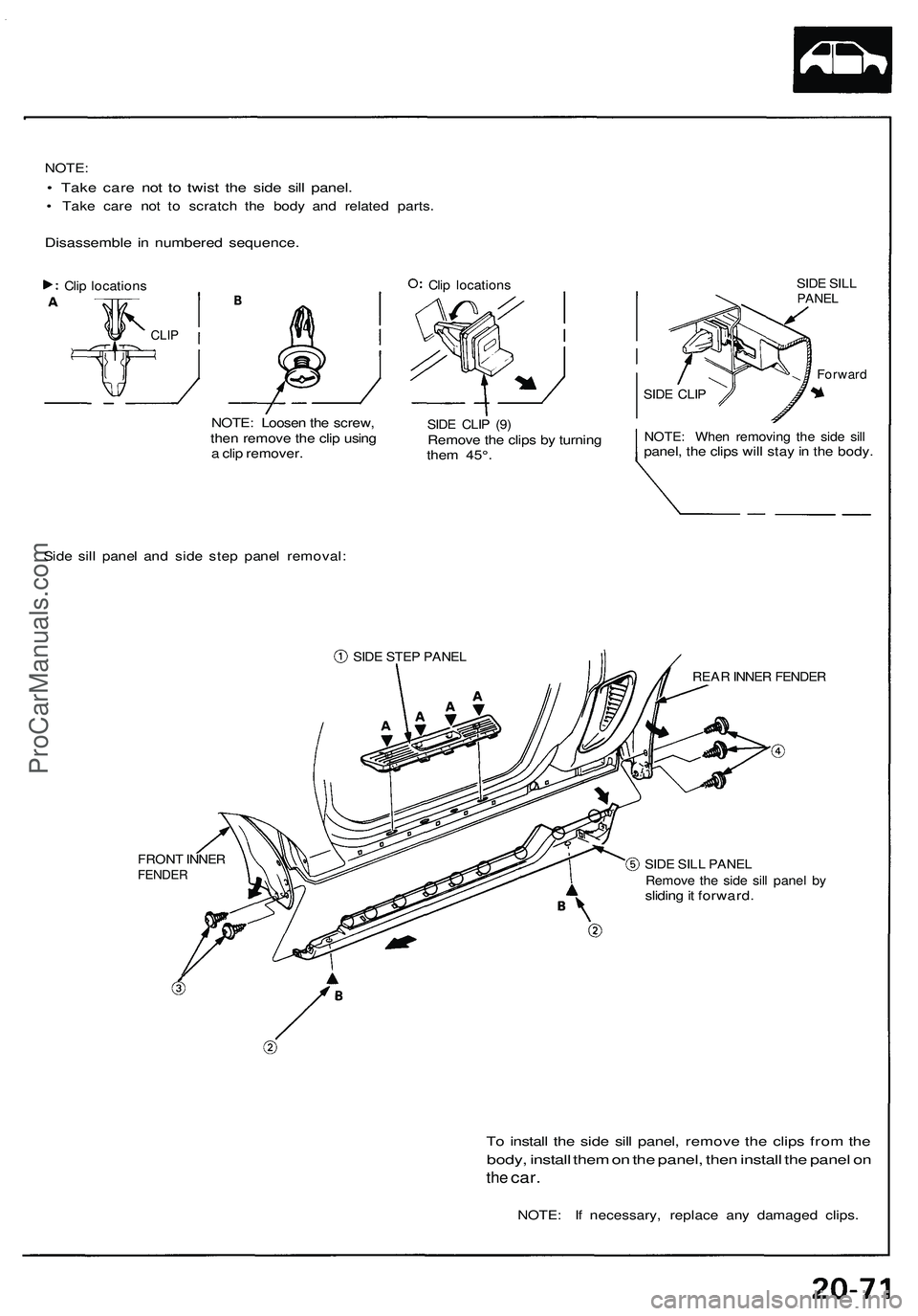
NOTE:
• Take care not to twist the side sill panel.
• Take care not to scratch the body and related parts.
Disassemble in numbered sequence.
NOTE: Loosen the screw,
then remove the clip using
a clip remover.
Clip locations
SIDE SILL
PANEL
SIDE CLIP (9)
Remove the clips by turning
them 45°.
SIDE CLIP
NOTE: When removing the side sill
panel, the clips will stay in the body.
Side sill panel and side step panel removal:
SIDE STEP PANEL
FRONT INNER
FENDER
REAR INNER FENDER
SIDE SILL PANEL
Remove the side sill panel by
sliding it forward.
To install the side sill panel, remove the clips from the
body, install them on the panel, then install the panel on
the
car.
NOTE: If necessary, replace any damaged clips.
Clip locations
CLIP
ForwardProCarManuals.com
Page 1129 of 1503
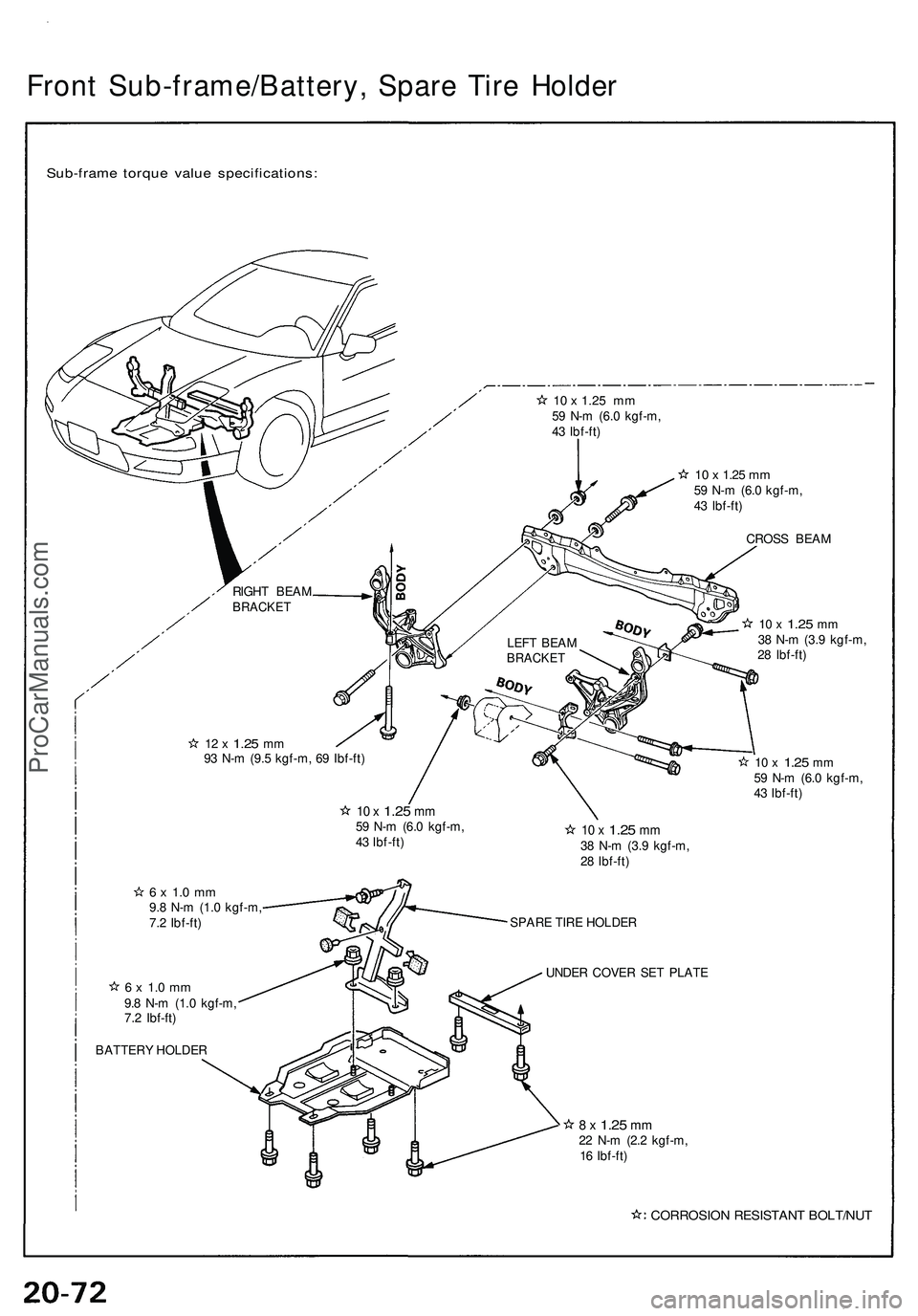
Front Sub-frame/Battery , Spar e Tir e Holde r
Sub-fram e torqu e valu e specifications :
10 x 1.25 mm59 N- m (6. 0 kgf-m ,
4 3 Ibf-ft )
10 x 1.2 5 m m59 N- m (6. 0 kgf-m ,
4 3 Ibf-ft )
CROS S BEA M
10 x 1.2 5 mm38 N- m (3. 9 kgf-m ,
2 8 Ibf-ft )
12 x 1.2 5 mm93 N- m (9. 5 kgf-m , 6 9 Ibf-ft )10 x 1.2 5 mm59 N- m (6. 0 kgf-m ,
4 3 Ibf-ft )
10 x 1.2 5 mm59 N- m (6. 0 kgf-m ,
4 3 Ibf-ft )10 x 1.2 5 mm38 N- m (3. 9 kgf-m ,
2 8 Ibf-ft )
6 x 1. 0 m m9.8 N- m (1. 0 kgf-m ,
7. 2 Ibf-ft )
6 x 1. 0 m m9.8 N- m (1. 0 kgf-m ,
7. 2 Ibf-ft ) SPAR
E TIR E HOLDE R
UNDE R COVE R SE T PLAT E
8 x 1.2 5 mm22 N- m (2. 2 kgf-m ,
1 6 Ibf-ft )
CORROSIO N RESISTAN T BOLT/NU T
RlGHT BEA MBRACKE T
BATTERY HOLDE R LEF
T BEA M
BRACKE T
ProCarManuals.com
Page 1130 of 1503
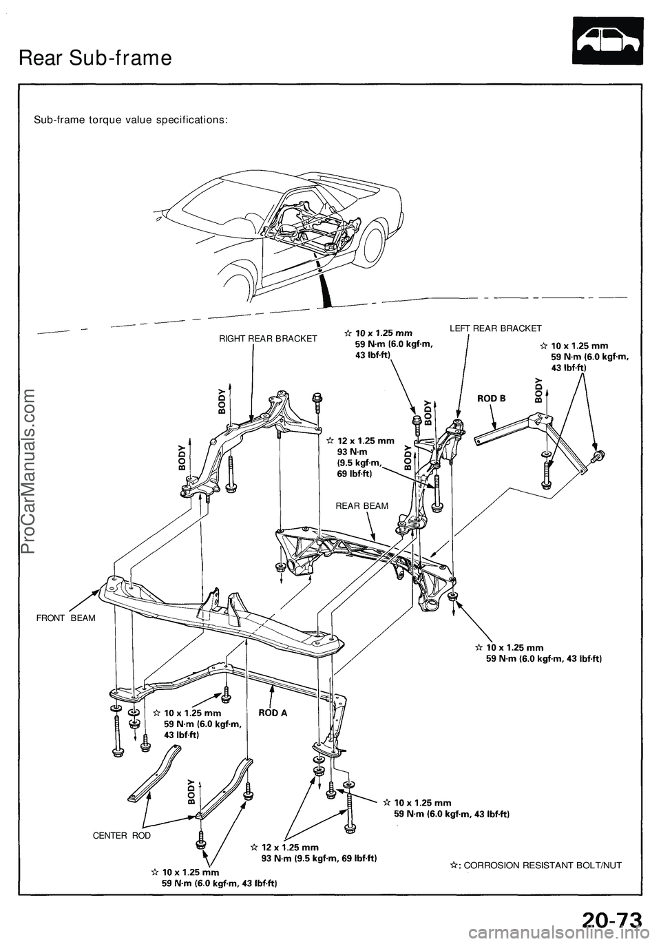
Rear Sub-frame
Sub-frame torque value specifications:
RIGHT REAR BRACKET
LEFT REAR BRACKET
FRONT BEAM
CENTER ROD
CORROSION RESISTANT BOLT/NUT
REAR BEAMProCarManuals.com
Trending: oil level, clutch, seats, radio controls, maintenance, fuel type, change wheel
