ACURA NSX 1997 Service Repair Manual
Manufacturer: ACURA, Model Year: 1997, Model line: NSX, Model: ACURA NSX 1997Pages: 1503, PDF Size: 57.08 MB
Page 1111 of 1503
Dashboard
Componen t Removal/Installatio n (cont'd )
SRS component s ar e locate d in thi s area . Revie w th e SR S componen t locations , precautions , an d procedure s in th e SR S
( sectio n 24 ) befor e performin g repair s o r service .
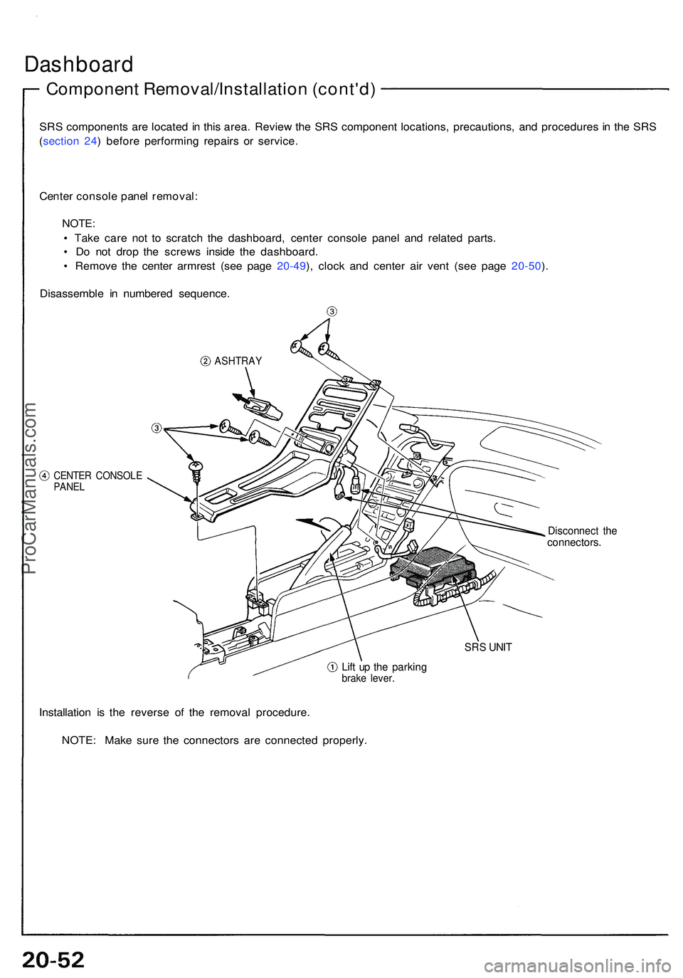
Cente r consol e pane l removal :
NOTE:
• Tak e car e no t t o scratc h th e dashboard , cente r consol e pane l an d relate d parts .
• D o no t dro p th e screw s insid e th e dashboard .
• Remov e th e cente r armres t (se e pag e 20-49 ), cloc k an d cente r ai r ven t (se e pag e 20-50 ).
Disassembl e i n numbere d sequence .
ASHTRAY
CENTER CONSOL EPANEL
Disconnec t th econnectors .
SRS UNI T
Lift u p th e parkin gbrake lever .
Installatio n i s th e revers e of the remova l procedure .
NOTE : Mak e sur e th e connector s ar e connecte d properly .
ProCarManuals.com
Page 1112 of 1503
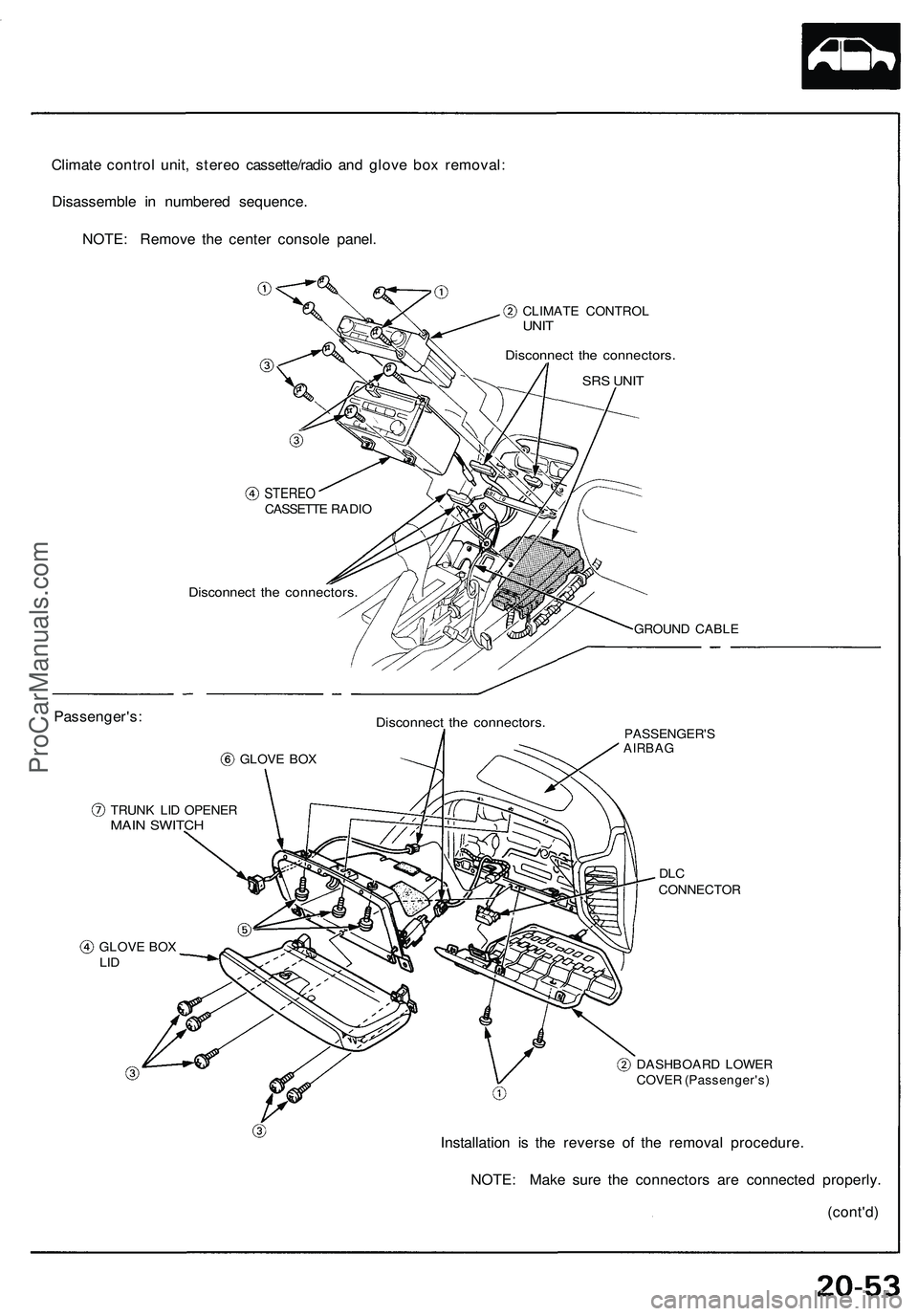
Climate control unit, stereo cassette/radio and glove box removal:
Disassemble in numbered sequence.
NOTE: Remove the center console panel.
CLIMATE CONTROL
UNIT
Disconnect the connectors.
SRS UNIT
Passenger's:
STEREO
CASSETTE RADIO
Disconnect the connectors.
GROUND CABLE
GLOVE BOX
Disconnect the connectors.
TRUNK LID OPENER
MAIN SWITCH
PASSENGER'S
AIRBAG
DLC
CONNECTOR
GLOVE BOX
LID
DASHBOARD LOWER
COVER (Passenger's)
Installation is the reverse of the removal procedure.
NOTE: Make sure the connectors are connected properly.
(cont'd)ProCarManuals.com
Page 1113 of 1503
Dashboard
Componen t Removal/Installatio n (cont'd )
SRS component s ar e locate d in thi s area . Revie w th e SR S componen t locations , precautions , an d procedure s in th e SR S
(sectio n 24 ) befor e performin g repair s o r service .
NOTE: Tak e car e no t t o scratc h th e dashboard ,
steerin g colum n an d relate d parts .
CAUTION : Whe n pryin g wit h a fla t ti p screw -
driver , wra p it wit h protectiv e tap e o r a sho p towe l
t o preven t damage .
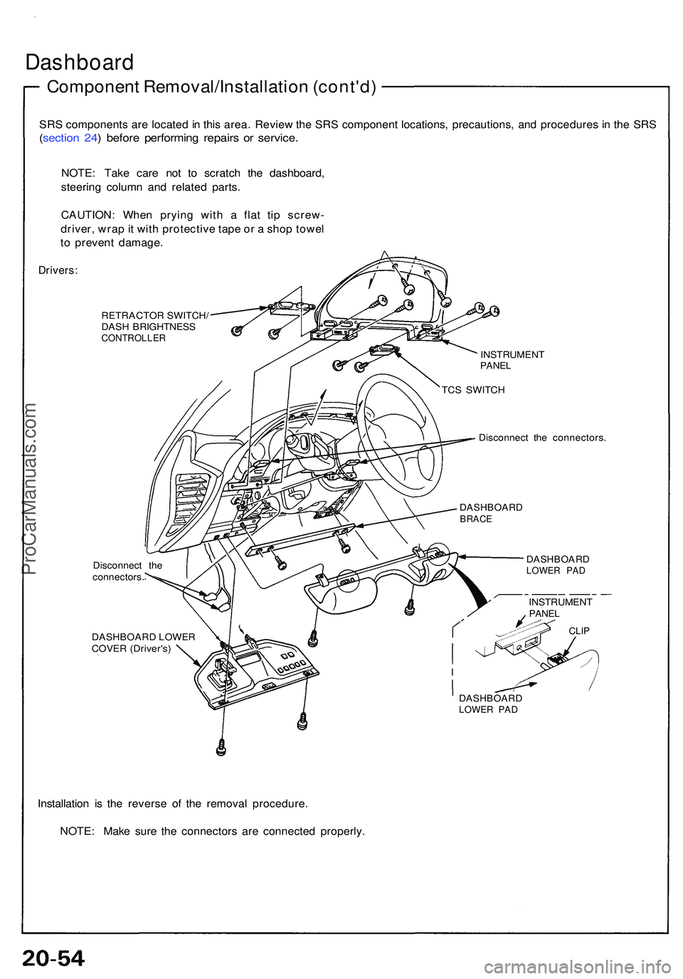
Drivers:
RETRACTO R SWITCH /
DAS H BRIGHTNES S
CONTROLLE R
Disconnect th e
connectors .
DASHBOAR D LOWE R
COVE R (Driver's )
Installation i s th e revers e of the remova l procedure .
NOTE : Mak e sur e th e connector s ar e connecte d properly .
Disconnec t th e connectors .
DASHBOAR DLOWER PA D
DASHBOAR DLOWER PA D
DASHBOAR DBRACE
INSTRUMEN TPANEL
CLIP
INSTRUMEN TPANEL
TCS SWITC H
ProCarManuals.com
Page 1114 of 1503
Replacement
SRS component s ar e locate d in thi s area . Revie w th e SR S
componen t locations , precautions , an d procedure s i n th e
SR S ( sectio n 24 ) befor e performin g repair s o r service .
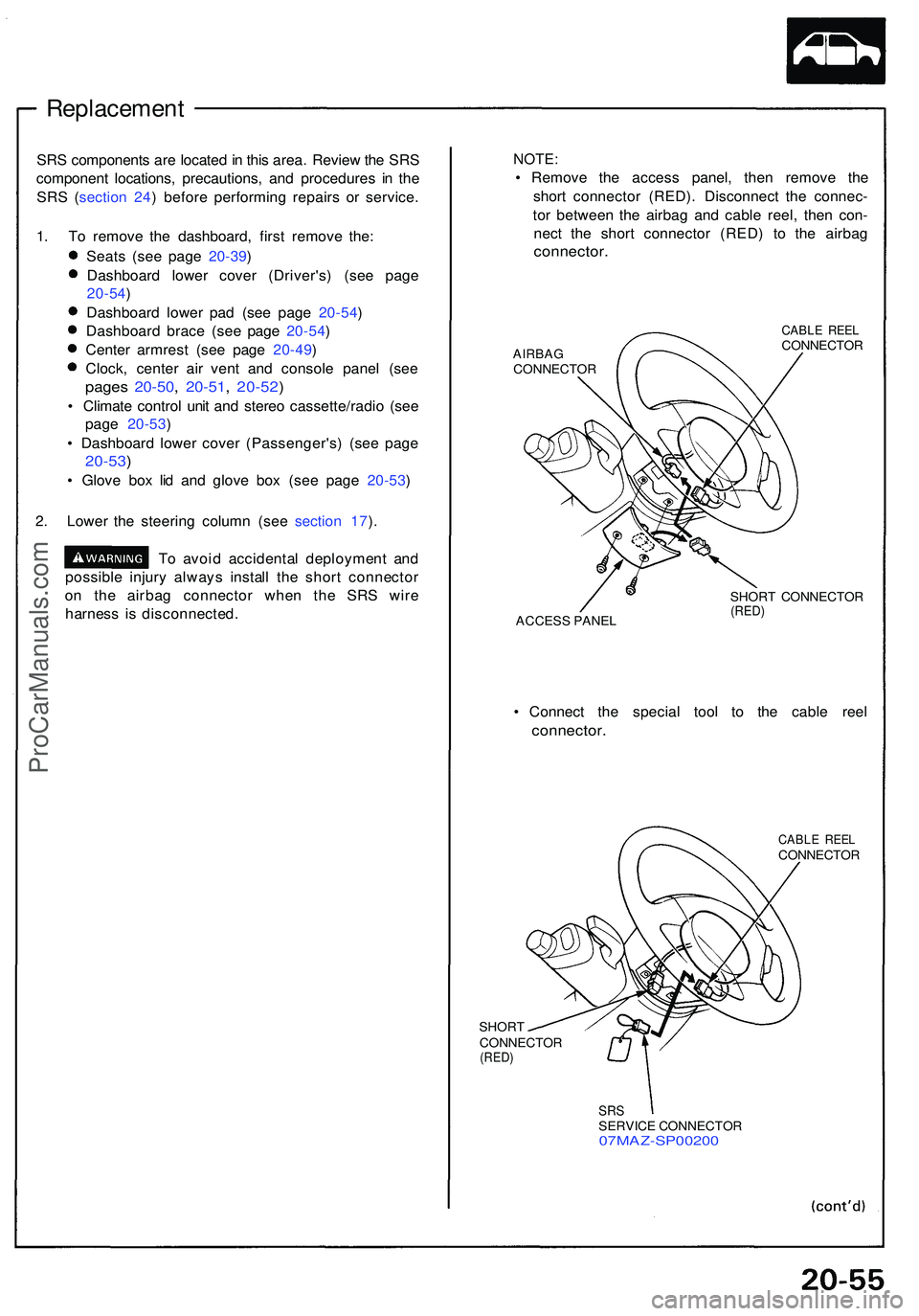
1 . T o remov e th e dashboard , firs t remov e the :
Seat s (se e pag e 20-39 )
Dashboar d lowe r cove r (Driver's ) (se e pag e
20-54 )
Dashboar d lowe r pa d (se e pag e 20-54 )
Dashboar d brac e (se e pag e 20-54 )
Cente r armres t (se e pag e 20-49 )
Clock , cente r ai r ven t an d consol e pane l (se e
page s 20-50 , 20-51 , 20-52 )
• Climat e contro l uni t an d stere o cassette/radi o (se e
pag e 20-53 )
• Dashboar d lowe r cove r (Passenger's ) (se e pag e
20-53 )
• Glov e bo x li d an d glov e bo x (se e pag e 20-53 )
2 . Lowe r th e steerin g colum n (se e sectio n 17 ).
T o avoi d accidenta l deploymen t an d
possibl e injur y alway s instal l th e shor t connecto r
o n th e airba g connecto r whe n th e SR S wir e
harnes s i s disconnected .
NOTE:
• Remov e th e acces s panel , the n remov e th e
shor t connecto r (RED) . Disconnec t th e connec -
to r betwee n th e airba g an d cabl e reel , the n con -
nec t th e shor t connecto r (RED ) t o th e airba g
connector .
AIRBAGCONNECTO R
CABLE REE LCONNECTO R
ACCES S PANE L SHOR
T CONNECTO R
(RED)
• Connec t th e specia l too l t o th e cabl e ree l
connector .
SHORT
CONNECTO R
(RED)
CABL E REE LCONNECTO R
SRSSERVIC E CONNECTO R07MAZ-SP0020 0
ProCarManuals.com
Page 1115 of 1503
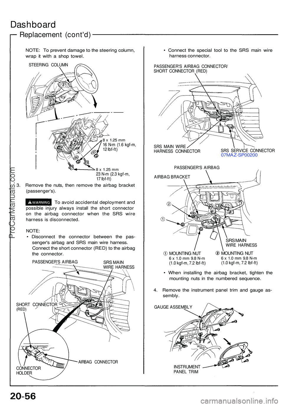
Dashboard
Replacemen t (cont'd )
NOTE: T o preven t damag e to th e steerin g column ,
wra p i t wit h a sho p towel .
STEERIN G COLUM N
8 x 1.2 5 mm16 N- m (1. 6 kgf-m ,
1 2 Ibf-ft )
8 x 1.2 5 mm23 N- m (2. 3 kgf-m ,
1 7 Ibf-ft )
3. Remov e th e nuts , the n remov e th e airba g bracke t
(passenger's) .
To avoi d accidenta l deploymen t an d
possibl e injur y alway s instal l th e shor t connecto r
on th e airba g connecto r whe n th e SR S wir e
harnes s i s disconnected .
NOTE:
• Disconnec t th e connecto r betwee n th e pas -
senger' s airba g an d SR S mai n wir e harness .
Connec t th e shor t connecto r (RED ) t o th e airba g
th e connector .
PASSENGER' S AIRBA GSRS MAI NWIRE HARNES S
SHOR T CONNECTO R
(RED)
AIRBA G CONNECTO R
• Connec t th e specia l too l t o th e SR S mai n wir e
harnes s connector .
PASSENGER' S AIRBA G CONNECTOR /
SHOR T CONNECTO R (RED )
SR S MAI N WIR E
HARNES S CONNECTO RSR
S SERVIC E CONNECTO R
07MAZ-SP0020 0
PASSENGER'S AIRBA G
AIRBA G BRACKE T
MOUNTING NU T6 x 1. 0 m m 9. 8 N- m(1.0 kgf-m , 7. 2 Ibf-ft )
SRS MAI NWIR E HARNES S
MOUNTING NU T6 x 1. 0 m m 9. 8 N- m(1.0 kgf-m , 7. 2 Ibf-ft )
• Whe n installin g th e airba g bracket , tighte n th e
mountin g nut s i n th e numbere d sequence .
4 . Remov e th e instrumen t pane l tri m an d gaug e as -
sembly .
GAUGE ASSEMBLY
INSTRUMEN TPANEL TRI M
CONNECTO
R
HOLDE R
ProCarManuals.com
Page 1116 of 1503
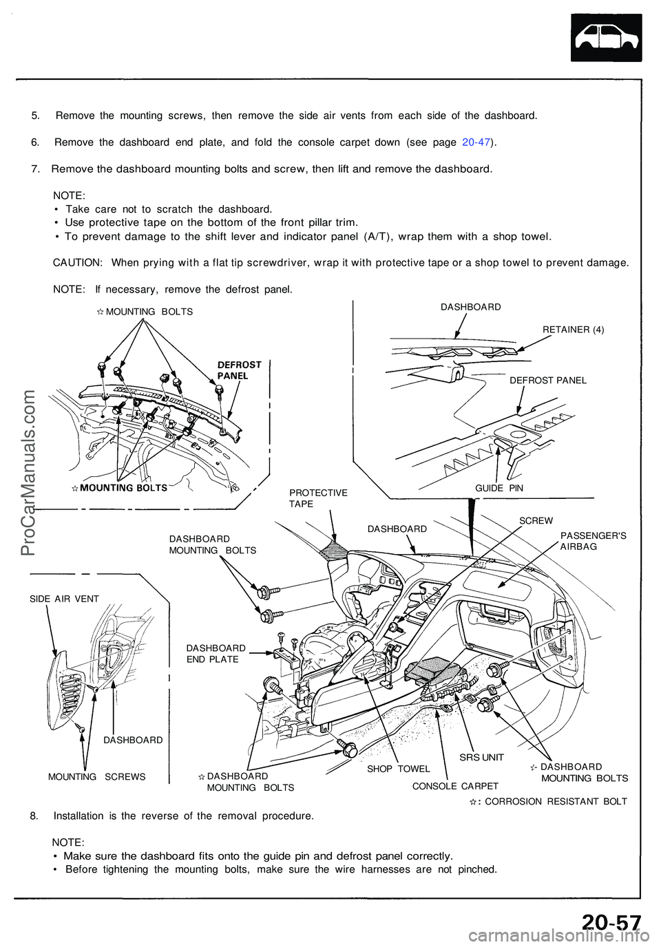
5. Remov e th e mountin g screws , the n remov e th e sid e ai r vent s fro m eac h sid e o f th e dashboard .
6 . Remov e th e dashboar d en d plate , an d fol d th e consol e carpe t dow n (se e pag e 20-47 ).
7 . Remov e th e dashboar d mountin g bolt s an d screw , the n lif t an d remov e th e dashboard .
NOTE:
• Tak e car e no t t o scratc h th e dashboard .
• Us e protectiv e tap e o n th e botto m o f th e fron t pilla r trim .
• T o preven t damag e t o th e shif t leve r an d indicato r pane l (A/T) , wra p the m wit h a sho p towel .
CAUTION : Whe n pryin g wit h a fla t ti p screwdriver , wra p it wit h protectiv e tap e o r a sho p towe l t o preven t damage .
NOTE : I f necessary , remov e th e defros t panel .
DASHBOAR D
RETAINER (4 )
DASHBOAR D
MOUNTIN G BOLT S
DASHBOAR D
EN D PLAT E
MOUNTIN G SCREW S PASSENGER'
S
AIRBAG
DASHBOAR DMOUNTING BOLT S SHO
P TOWE L
CONSOL E CARPE T - DASHBOAR
D MOUNTING BOLT S
8. Installatio n i s th e revers e of the remova l procedure .
NOTE :
• Mak e sur e th e dashboar d fit s ont o th e guid e pi n an d defros t pane l correctly .
• Befor e tightenin g th e mountin g bolts , mak e sur e th e wir e harnesse s ar e no t pinched .
PROTECTIV ETAPE
DASHBOAR D SCRE
W
SRS UNI T
SIDE AI R VEN T
CORROSION RESISTAN T BOL T
DASHBOAR
D GUID
E PI N
DEFROS
T PANE L
MOUNTIN
G BOLT S
ProCarManuals.com
Page 1117 of 1503
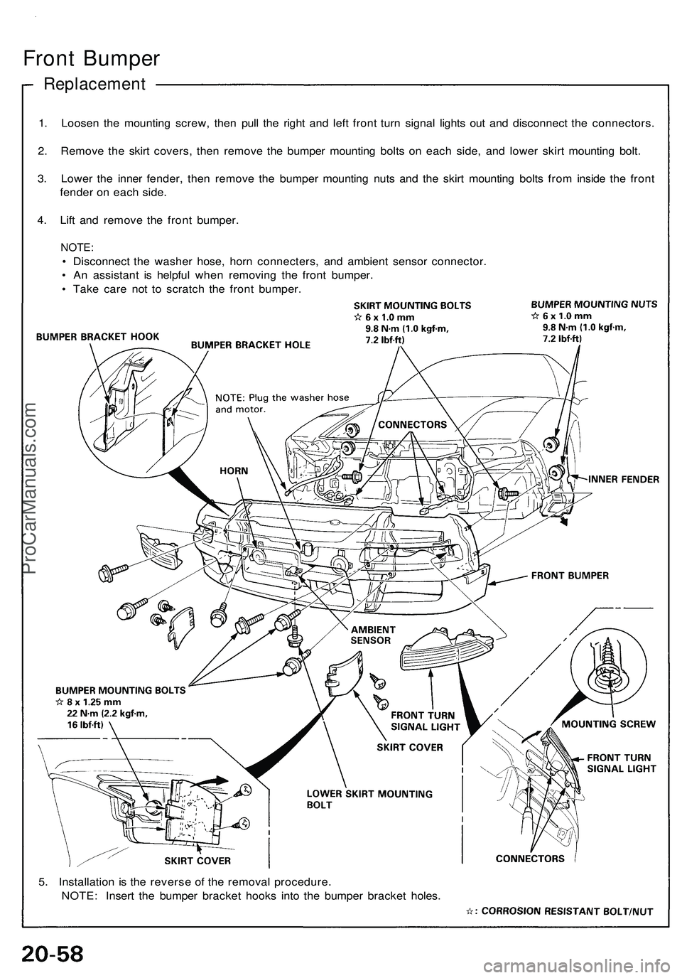
Front Bumper
Replacement
1. Loosen the mounting screw, then pull the right and left front turn signal lights out and disconnect the connectors.
2. Remove the skirt covers, then remove the bumper mounting bolts on each side, and lower skirt mounting bolt.
3. Lower the inner fender, then remove the bumper mounting nuts and the skirt mounting bolts from inside the front
fender on each side.
4. Lift and remove the front bumper.
NOTE:
• Disconnect the washer hose, horn connecters, and ambient sensor connector.
• An assistant is helpful when removing the front bumper.
• Take care not to scratch the front bumper.
5. Installation is the reverse of the removal procedure.
NOTE: Insert the bumper bracket hooks into the bumper bracket holes.ProCarManuals.com
Page 1118 of 1503
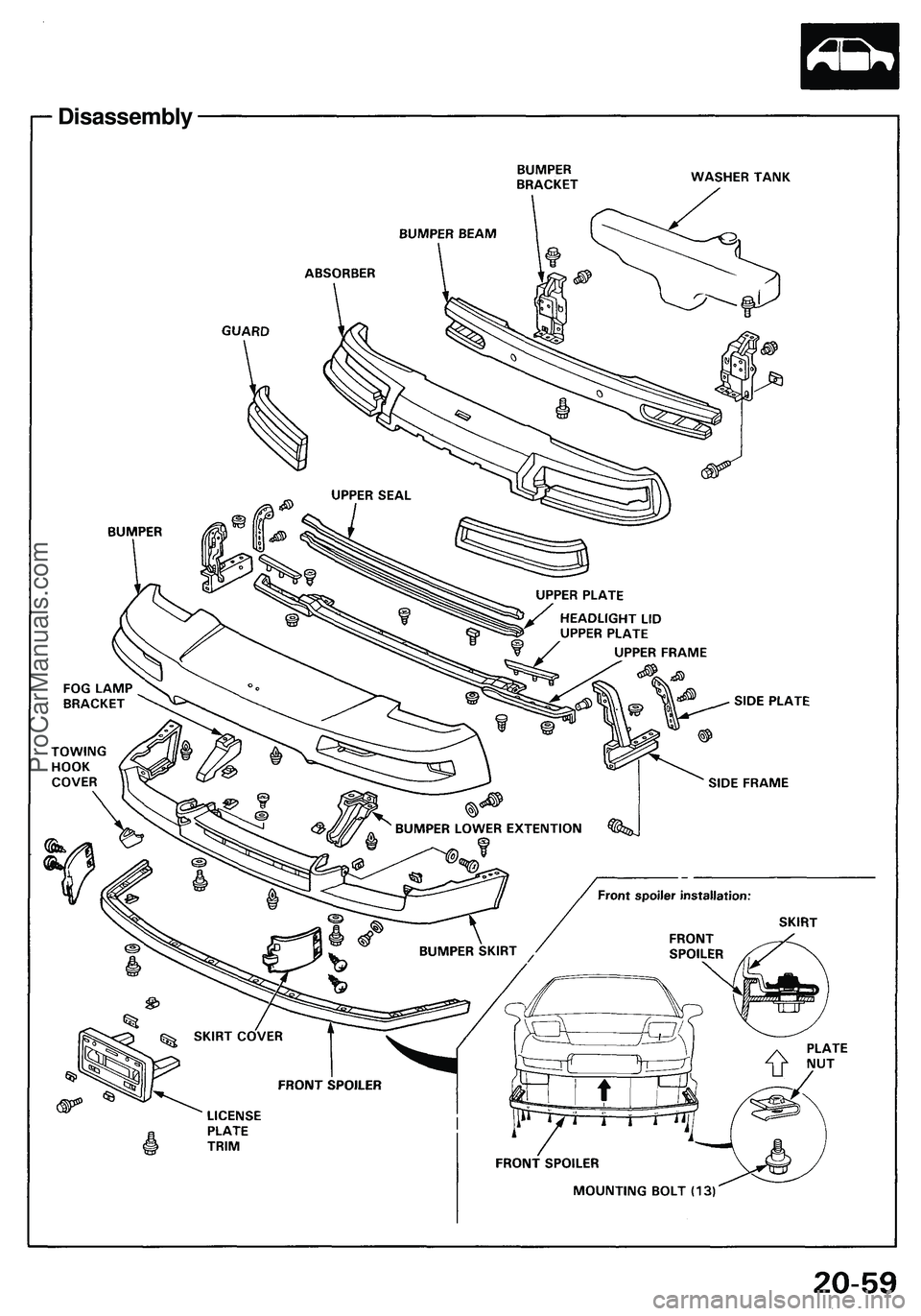
Disassembly
ProCarManuals.com
Page 1119 of 1503
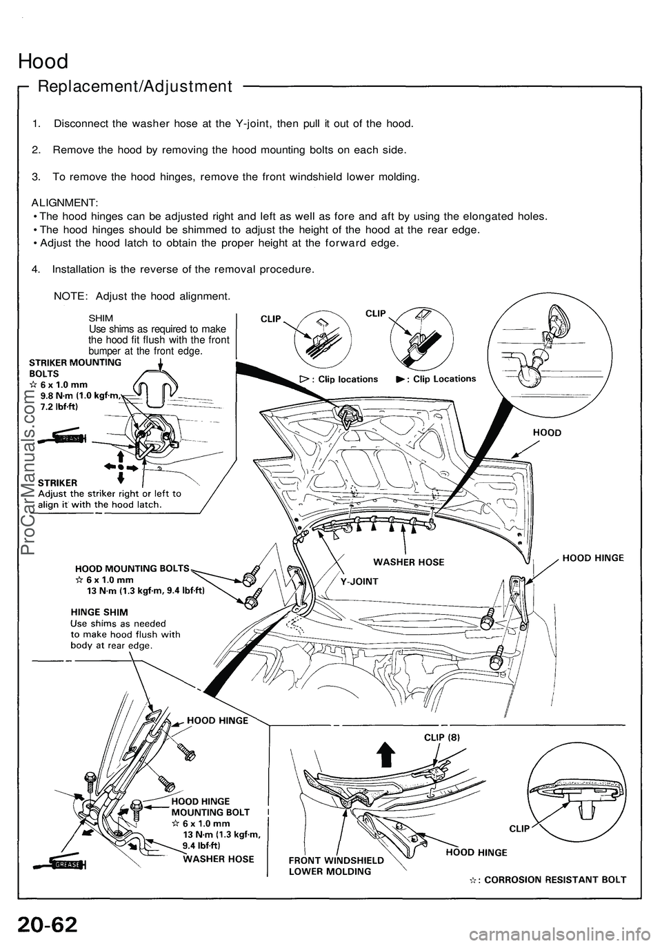
Hood
Replacement/Adjustment
1. Disconnect the washer hose at the Y-joint, then pull it out of the hood.
2. Remove the hood by removing the hood mounting bolts on each side.
3. To remove the hood hinges, remove the front windshield lower molding.
ALIGNMENT:
• The hood hinges can be adjusted right and left as well as fore and aft by using the elongated holes.
• The hood hinges should be shimmed to adjust the height of the hood at the rear edge.
• Adjust the hood latch to obtain the proper height at the forward edge.
4. Installation is the reverse of the removal procedure.
NOTE: Adjust the hood alignment.
SHIM
Use shims as required to make
the hood fit flush with the front
bumper at the front edge.ProCarManuals.com
Page 1120 of 1503
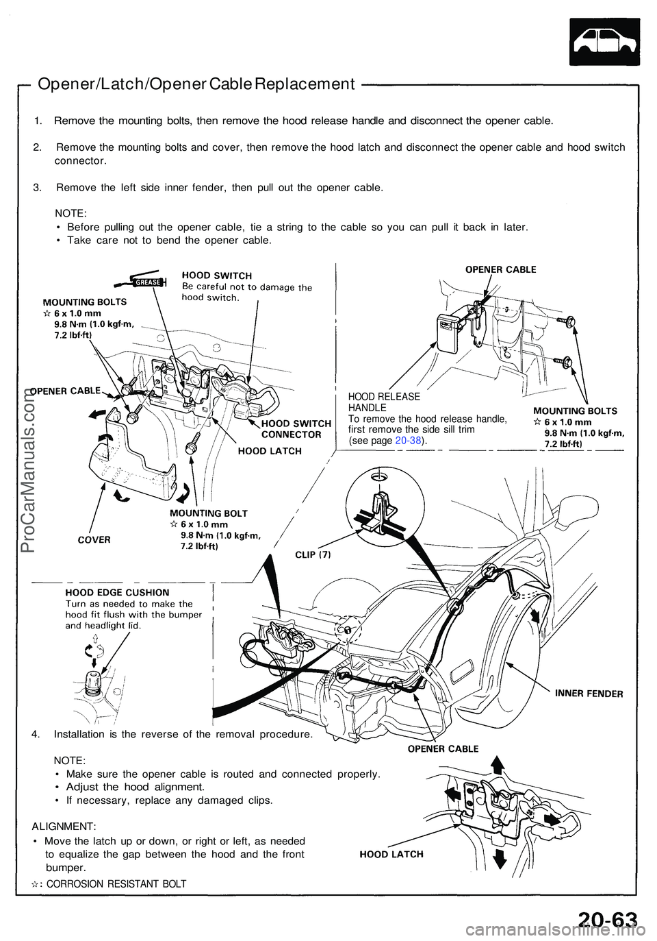
Opener/Latch/Opener Cabl e Replacemen t
1. Remov e th e mountin g bolts , the n remov e th e hoo d releas e handl e an d disconnec t th e opene r cable .
2. Remov e th e mountin g bolt s an d cover , the n remov e th e hoo d latc h an d disconnec t th e opene r cabl e an d hoo d switc h
connector .
3 . Remov e th e lef t sid e inne r fender , the n pul l ou t th e opene r cable .
NOTE:
• Befor e pullin g ou t th e opene r cable , ti e a strin g t o th e cabl e s o yo u ca n pul l i t bac k i n later .
• Tak e car e no t t o ben d th e opene r cable .
HOOD RELEAS EHANDLETo remov e th e hoo d releas e handle ,first remov e th e sid e sil l tri m(se e pag e 20-38 ).
4 . Installatio n i s th e revers e o f th e remova l procedure .
NOTE:
• Mak e sur e th e opene r cabl e i s route d an d connecte d properly .
• Adjus t th e hoo d alignment .
• I f necessary , replac e an y damage d clips .
ALIGNMENT :
• Mov e th e latc h u p o r down , o r righ t o r left , a s neede d
t o equaliz e th e ga p betwee n th e hoo d an d th e fron t
bumper .
CORROSIO N RESISTAN T BOL T
ProCarManuals.com