ACURA NSX 1997 Service Repair Manual
Manufacturer: ACURA, Model Year: 1997, Model line: NSX, Model: ACURA NSX 1997Pages: 1503, PDF Size: 57.08 MB
Page 631 of 1503
Intake Ai r Bypas s (IAB ) Contro l Valv e Testin g
CAUTION : D o no t adjus t th e IA B contro l valv e full-clos e
screw . I t wa s prese t a t th e factory .
1 . Chec k th e IA B contro l valv e shaf t fo r bindin g o r
sticking .
2 . Chec k th e IA B contro l valv e fo r smoot h movement .
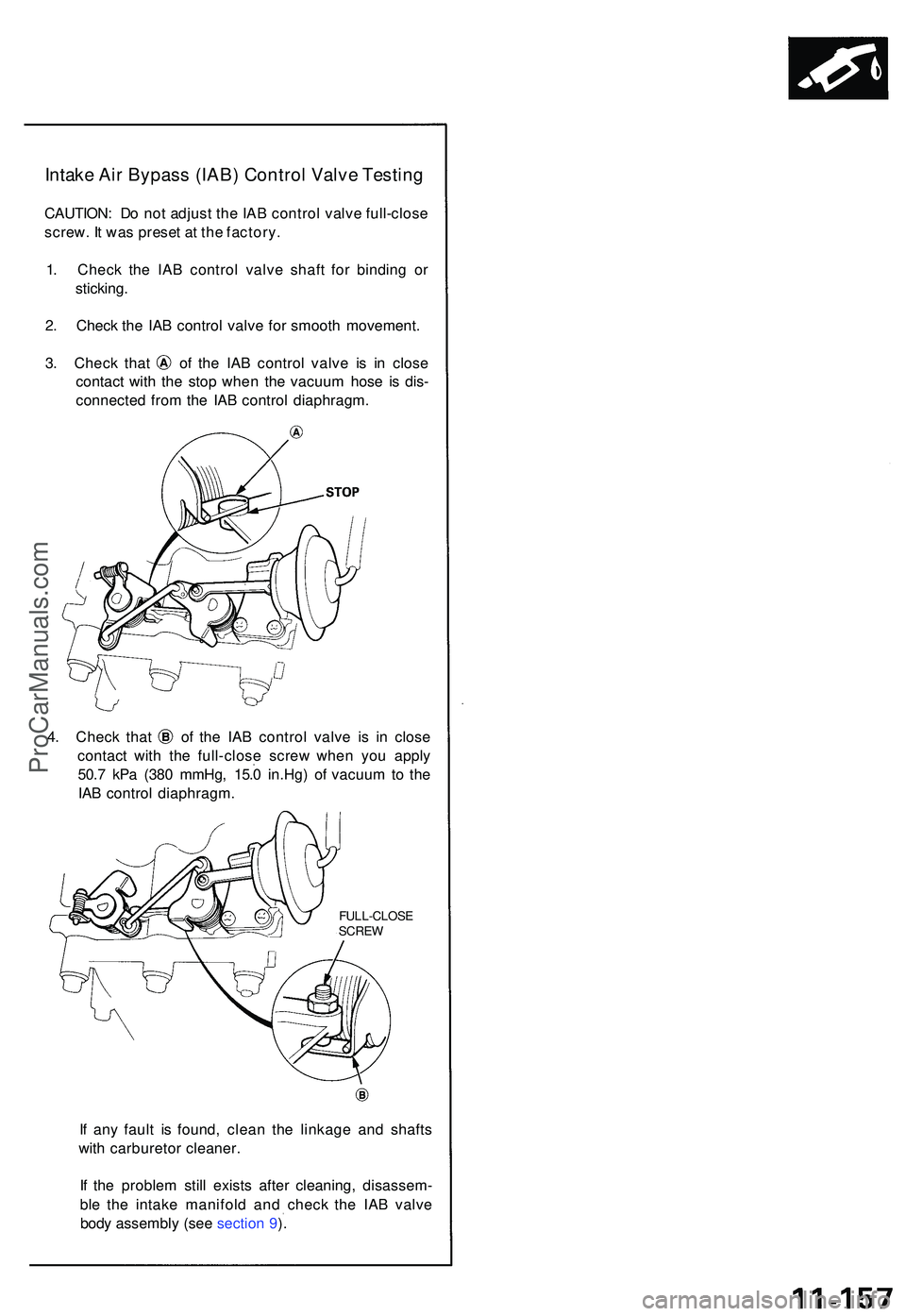
3. Chec k tha t o f th e IA B contro l valv e i s i n clos e
contac t wit h th e sto p whe n th e vacuu m hos e i s dis -
connecte d fro m th e IA B contro l diaphragm .
4. Chec k tha t o f th e IA B contro l valv e i s i n clos e
contac t wit h th e full-clos e scre w whe n yo u appl y
50. 7 kP a (38 0 mmHg , 15. 0 in.Hg ) o f vacuu m to th e
IA B contro l diaphragm .
FULL-CLOS E
SCRE W
If an y faul t i s found , clea n th e linkag e an d shaft s
wit h carbureto r cleaner .
I f th e proble m stil l exist s afte r cleaning , disassem -
bl e th e intak e manifol d an d chec k th e IA B valv e
bod y assembl y (se e sectio n 9 ).
ProCarManuals.com
Page 632 of 1503
Emission Contro l Syste m
System Descriptio n
The emissio n contro l syste m include s tw o Thre e Wa y
Catalyti c Converter s (TWCs) , Exhaus t Ga s Recirculatio n
(EGR ) system , Positiv e Crankcas e Ventilatio n (PCV ) sys -
te m an d Evaporativ e Emissio n (EVAP ) Contro l system .
Th e emissio n contro l syste m is designe d t o mee t federa l
an d stat e emissio n standards .
Tailpipe Emissio n
1. Star t th e engine . Hol d th e engine at 3,00 0 rp m wit h
no loa d (A/ T in o r position , M/ T in neutral ) unti l
th e radiato r fa n come s on , the n le t i t idle .
2 . Connec t a tachometer .
3 . Chec k an d adjus t th e idl e speed , i f necessar y (se e
pag e 11-129 ).
4 . War m u p an d calibrat e th e C O mete r accordin g t o
th e mete r manufacturer' s instructions .
5 . Chec k idl e C O wit h th e headlights , heate r blower ,
rea r windo w defogger , coolin g fan , an d ai r condi -
tione r off .
NOTE : (Canada ) Pul l th e parkin g brak e leve r up .
Star t th e engine , the n chec k tha t th e headlight s ar e
off.
CO mete r shoul d indicat e 0.1 % maximum .
Inspection
any ope n flam e awa y fro m you r wor k area .
D
o no t smok e durin g thi s procedure . Kee p
ProCarManuals.com
Page 633 of 1503
Three Wa y Catalyti c Converte r (TWC)
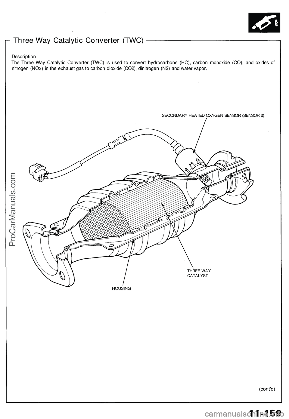
Descriptio n
Th e Thre e Wa y Catalyti c Converte r (TWC ) i s use d t o conver t hydrocarbon s (HC) , carbo n monoxid e (CO) , an d oxide s o f
nitroge n (NOx ) i n th e exhaus t ga s t o carbo n dioxid e (CO2) , dinitroge n (N2 ) an d wate r vapor .
SECONDAR Y HEATE D OXYGE N SENSO R (SENSO R 2 )
THRE E WA Y
CATALYS T
HOUSING
(cont'd)
ProCarManuals.com
Page 634 of 1503
Exhaust Gas Recirculation (EGR) System
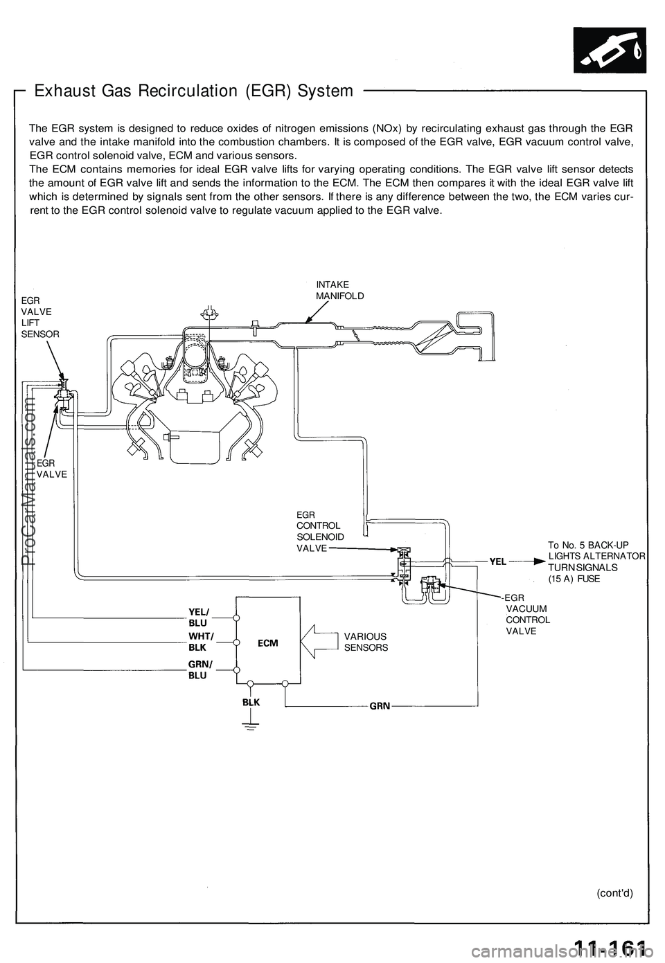
The EGR system is designed to reduce oxides of nitrogen emissions (NOx) by recirculating exhaust gas through the EGR
valve and the intake manifold into the combustion chambers. It is composed of the EGR valve, EGR vacuum control valve,
EGR control solenoid valve, ECM and various sensors.
The ECM contains memories for ideal EGR valve lifts for varying operating conditions. The EGR valve lift sensor detects
the amount of EGR valve lift and sends the information to the ECM. The ECM then compares it with the ideal EGR valve lift
which is determined by signals sent from the other sensors. If there is any difference between the two, the ECM varies cur-
rent to the EGR control solenoid valve to regulate vacuum applied to the EGR valve.
EGR
VALVE
LIFT
SENSOR
INTAKE
MANIFOLD
EGR
CONTROL
SOLENOID
VALVE
To No. 5 BACK-UP
LIGHTS ALTERNATOR
TURN SIGNALS
(15 A) FUSE
-EGR
VACUUM
CONTROL
VALVE
(cont'd)
EGR
VALVE
VARIOUS
SENSORSProCarManuals.com
Page 635 of 1503
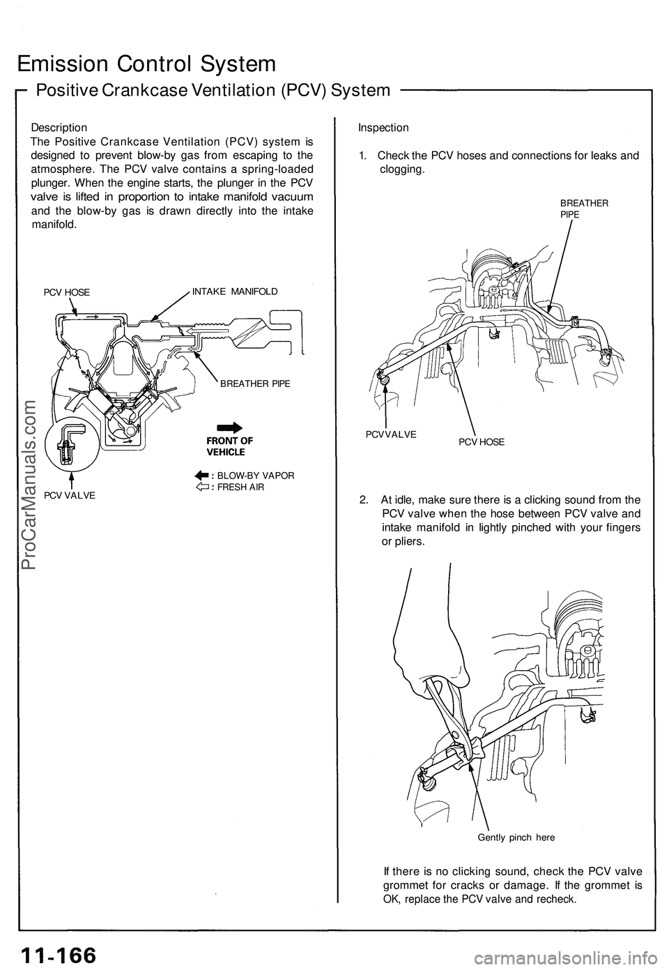
Emission Control System
Positive Crankcase Ventilation (PCV) System
Description
The Positive Crankcase Ventilation (PCV) system is
designed to prevent blow-by gas from escaping to the
atmosphere. The PCV valve contains a spring-loaded
plunger. When the engine starts, the plunger in the PCV
valve is lifted in proportion to intake manifold vacuum
and the blow-by gas is drawn directly into the intake
manifold.
PCV HOSE
INTAKE MANIFOLD
PCV VALVE
Inspection
1. Check the PCV hoses and connections for leaks and
clogging.
BREATHER
PIPE
PCV VALVE
PCV HOSE
2. At idle, make sure there is a clicking sound from the
PCV valve when the hose between PCV valve and
intake manifold in lightly pinched with your fingers
or pliers.
Gently pinch here
If there is no clicking sound, check the PCV valve
grommet for cracks or damage. If the grommet is
OK, replace the PCV valve and recheck.
BLOW-BY VAPOR
FRESH AIR
BREATHER PIPEProCarManuals.com
Page 636 of 1503
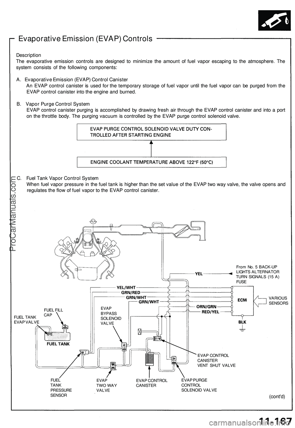
Evaporative Emission (EVAP) Controls
Description
The evaporative emission controls are designed to minimize the amount of fuel vapor escaping to the atmosphere. The
system consists of the following components:
A. Evaporative Emission (EVAP) Control Canister
An EVAP control canister is used for the temporary storage of fuel vapor until the fuel vapor can be purged from the
EVAP control canister into the engine and burned.
B. Vapor Purge Control System
EVAP control canister purging is accomplished by drawing fresh air through the EVAP control canister and into a port
on the throttle body. The purging vacuum is controlled by the EVAP purge control solenoid valve.
C. Fuel Tank Vapor Control System
When fuel vapor pressure in the fuel tank is higher than the set value of the EVAP two way valve, the valve opens and
regulates the flow of fuel vapor to the EVAP control canister.
From No. 5 BACK-UP
LIGHTS ALTERNATOR
TURN SIGNALS (15 A)
FUSE
FUEL TANK
EVAP VALVE
EVAP
BYPASS
SOLENOID
VALVE
VARIOUS
SENSORS
EVAP CONTROL
CANISTER
VENT SHUT VALVE
FUEL
TANK
PRESSURE
SENSOR
EVAP
TWO WAY
VALVE
EVAP CONTROL
CANISTER
EVAP PURGE
CONTROL
SOLENOID VALVE
(cont'd)
FUEL FILL
CAPProCarManuals.com
Page 637 of 1503
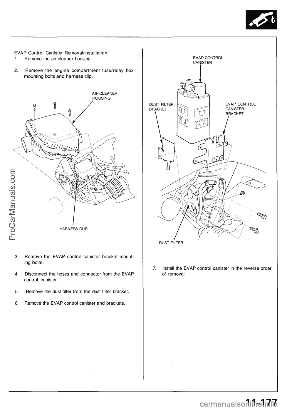
EVAP Control Canister Removal/Installation
1. Remove the air cleaner housing.
2. Remove the engine compartment fuse/relay box
mounting bolts and harness clip.
AIR CLEANER
HOUSING
HARNESS CLIP
3. Remove the EVAP control canister bracket mount-
ing bolts.
4. Disconnect the hoses and connector from the EVAP
control canister.
5. Remove the dust filter from the dust filter bracket.
6. Remove the EVAP control canister and brackets.
EVAP CONTROL
CANISTER
DUST FILTER
BRACKET
EVAP CONTROL
CANISTER
BRACKET
DUST FILTER
7. Install the EVAP control canister in the reverse order
of removal.ProCarManuals.com
Page 638 of 1503
Emission Contro l Syste m
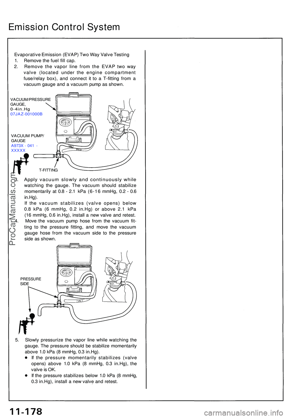
Evaporativ e Emissio n (EVAP ) Tw o Wa y Valv e Testin g
1 . Remov e th e fue l fil l cap .
2 . Remov e th e vapo r lin e fro m th e EVA P tw o wa y
valv e (locate d unde r th e engin e compartmen t
fuse/rela y box) , an d connec t i t t o a T-fittin g fro m a
vacuu m gaug e an d a vacuu m pum p a s shown .
VACUUM/PRESSUR E
GAUGE ,
0-4in.H g07JAZ-001000 B
VACUUM PUMP /GAUGE
A973 X - 04 1 -
XXXX X
3. Appl y vacuu m slowl y an d continuousl y whil e
watchin g th e gauge . Th e vacuu m shoul d stabiliz e
momentaril y a t 0. 8 - 2. 1 kP a (6-1 6 mmHg , 0. 2 - 0. 6
in.Hg) .
I f th e vacuu m stabilize s (valv e opens ) belo w
0. 8 kP a ( 6 mmHg , 0. 2 in.Hg ) o r abov e 2. 1 kP a
(1 6 mmHg , 0. 6 in.Hg) , instal l a ne w valv e an d retest .
4 . Mov e th e vacuu m pum p hos e fro m th e vacuu m fit -
tin g t o th e pressur e fitting , an d mov e th e vacuu m
gaug e hos e fro m th e vacuu m sid e t o th e pressur e
sid e a s shown .
PRESSUR ESIDE
5. Slowl y pressuriz e th e vapo r lin e whil e watchin g th e
gauge . Th e pressur e shoul d b e stabiliz e momentaril y
abov e 1. 0 kP a ( 8 mmHg , 0. 3 in.Hg) .
I f th e pressur e momentaril y stabilize s (valv e
opens ) abov e 1. 0 kP a ( 8 mmHg , 0. 3 in.Hg) , th e
valv e is OK .
I f th e pressur e stabilize s belo w 1. 0 kP a ( 8 mmHg ,
0. 3 in.Hg) , instal l a ne w valv e an d retest .
T-FITTIN G
ProCarManuals.com
Page 639 of 1503
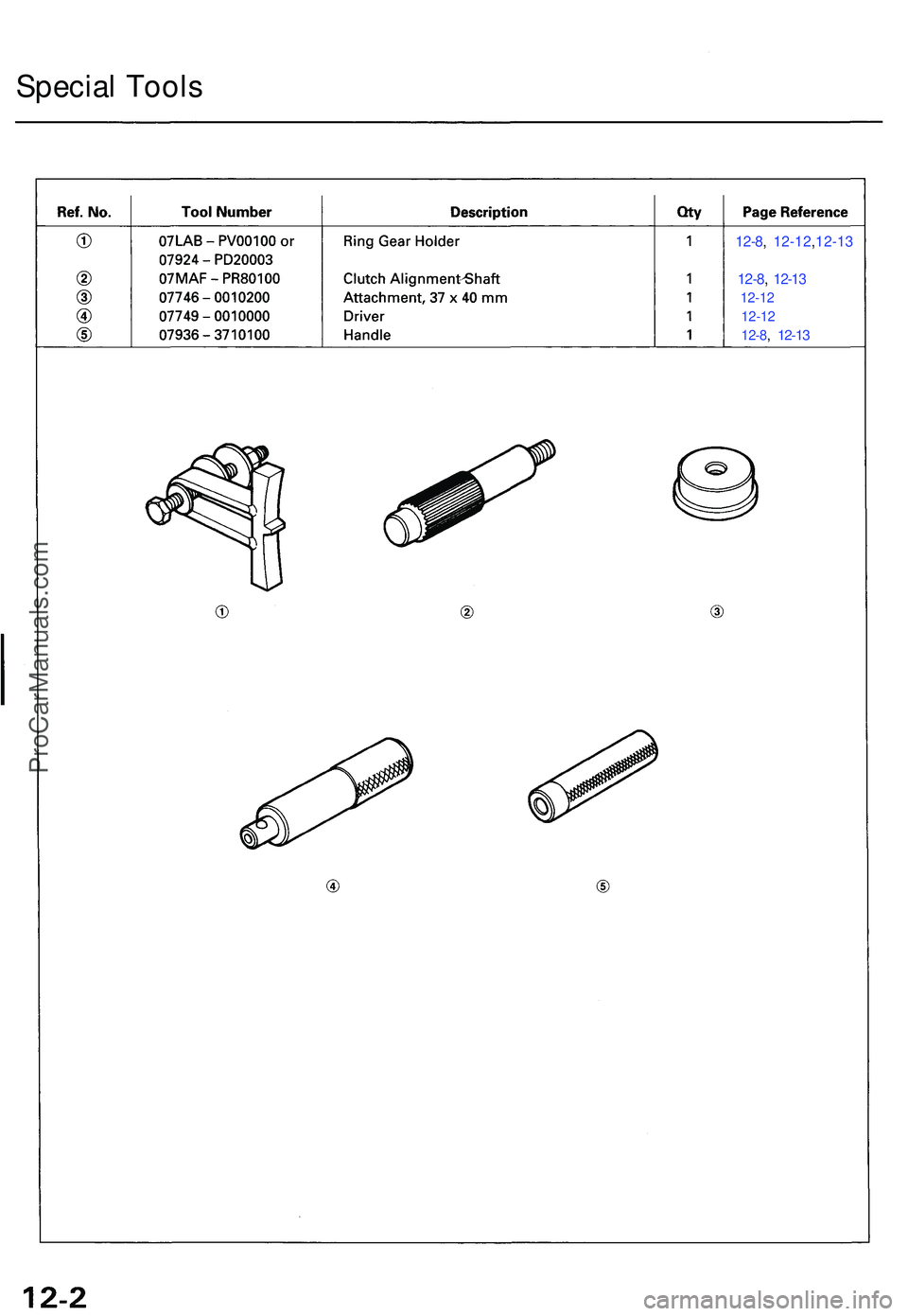
Special Tool s
12-8, 12-12 ,12-1 3
12-8 ,
12-1 3
12-1 2
12-1 2
12-8 ,
12-1 3
ProCarManuals.com
Page 640 of 1503
Description
Dual Mas s Flywhee l
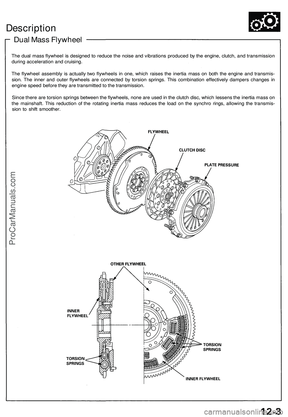
The dua l mas s flywhee l i s designe d t o reduc e th e nois e an d vibration s produce d b y th e engine , clutch , an d transmissio n
durin g acceleratio n an d cruising .
Th e flywhee l assembl y i s actuall y tw o flywheel s i n one , whic h raise s th e inerti a mas s o n bot h th e engin e an d transmis -
sion . Th e inne r an d oute r flywheel s ar e connecte d b y torsio n springs . Thi s combinatio n effectivel y damper s change s i n
engin e spee d befor e the y ar e transmitte d to th e transmission .
Sinc e ther e ar e torsio n spring s betwee n th e flywheels , non e ar e use d in th e clutc h disc , whic h lessen s th e inerti a mas s o n
th e mainshaft . Thi s reductio n o f th e rotatin g inerti a mas s reduce s th e loa d o n th e synchr o rings , allowin g th e transmis -
sio n t o shif t smoother .
ProCarManuals.com