ACURA NSX 1997 Service Repair Manual
Manufacturer: ACURA, Model Year: 1997, Model line: NSX, Model: ACURA NSX 1997Pages: 1503, PDF Size: 57.08 MB
Page 621 of 1503
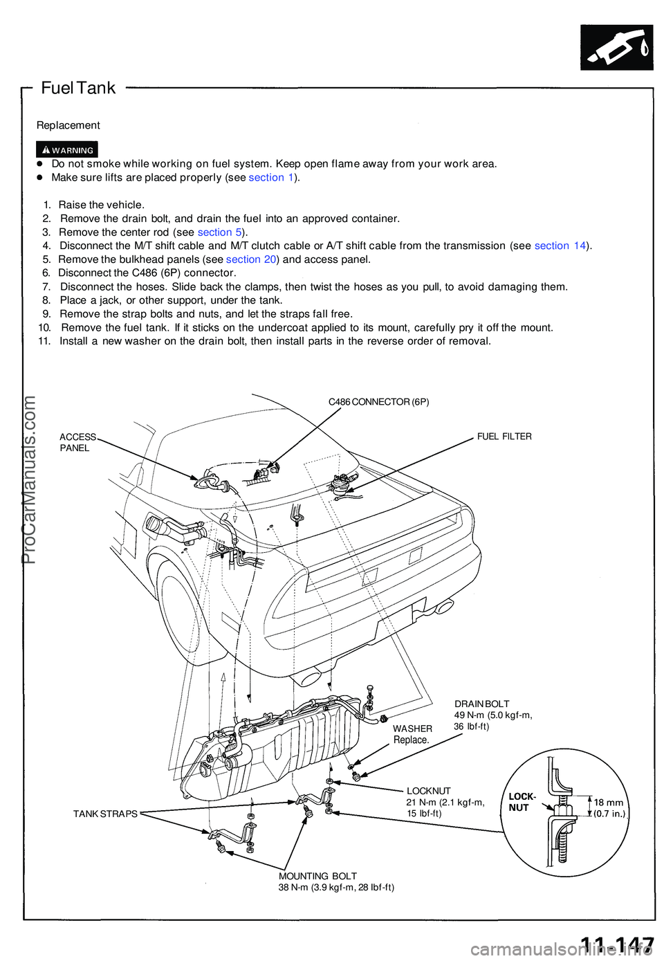
Fuel Tan k
Replacemen t
D o no t smok e whil e workin g o n fue l system . Kee p ope n flam e awa y fro m you r wor k area .
Mak e sur e lift s ar e place d properl y (se e sectio n 1 ).
1 . Rais e th e vehicle .
2 . Remov e th e drai n bolt , an d drai n th e fue l int o a n approve d container .
3 . Remov e th e cente r ro d (se e sectio n 5 ).
4 . Disconnec t th e M/ T shif t cabl e an d M/ T clutc h cabl e o r A/ T shif t cabl e fro m th e transmissio n (se e sectio n 14 ).
5 . Remov e th e bulkhea d panel s (se e sectio n 20 ) an d acces s panel .
6 . Disconnec t th e C48 6 (6P ) connector .
7 . Disconnec t th e hoses . Slid e bac k th e clamps , the n twis t th e hose s a s yo u pull , t o avoi d damagin g them .
8 . Plac e a jack , o r othe r support , unde r th e tank .
9 . Remov e th e stra p bolt s an d nuts , an d le t th e strap s fal l free .
10 . Remov e th e fue l tank . I f i t stick s o n th e undercoa t applie d t o it s mount , carefull y pr y i t of f th e mount .
11 . Instal l a ne w washe r o n th e drai n bolt , the n instal l part s i n th e revers e orde r o f removal .
C486 CONNECTO R (6P )
ACCES SPANELFUEL FILTE R
DRAIN BOL T
4 9 N- m (5. 0 kgf-m ,
36 Ibf-ft )
TANK STRAP S LOCKNU
T
2 1 N- m (2. 1 kgf-m ,15 Ibf-ft )
MOUNTIN G BOL T
3 8 N- m (3. 9 kgf-m , 2 8 Ibf-ft )
WASHE RReplace.
ProCarManuals.com
Page 622 of 1503
Intake Ai r Syste m
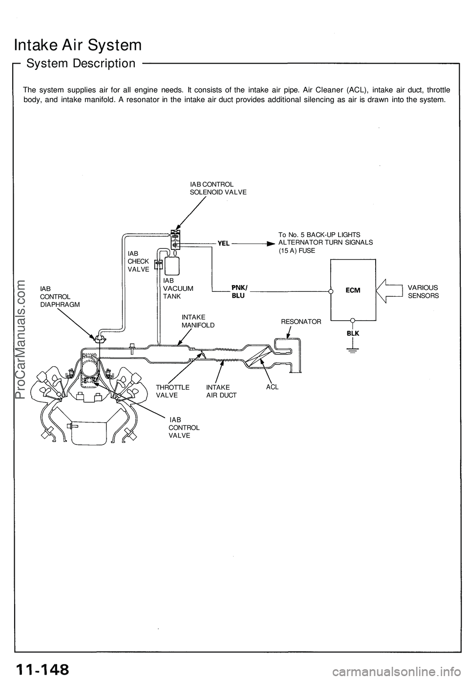
System Descriptio n
The syste m supplie s ai r fo r al l engine needs. I t consist s o f th e intak e ai r pipe . Ai r Cleane r (ACL) , intak e ai r duct , throttl e
body , an d intak e manifold . A resonato r i n th e intak e ai r duc t provide s additiona l silencin g a s ai r i s draw n int o th e system .
IAB CONTRO L
SOLENOI D VALV E
To No . 5 BACK-U P LIGHT S
ALTERNATO R TUR N SIGNAL S
(1 5 A ) FUS E
IABCONTRO L
DIAPHRAG M
THROTTLE INTAK E
VALV E AI R DUC T
VARIOU SSENSOR S
ACL
IABCONTRO LVALVE
INTAK E
MANIFOL DRESONATO R
IABCHEC KVALV E
IABVACUU MTANK
ProCarManuals.com
Page 623 of 1503
Air Cleaner (ACL)
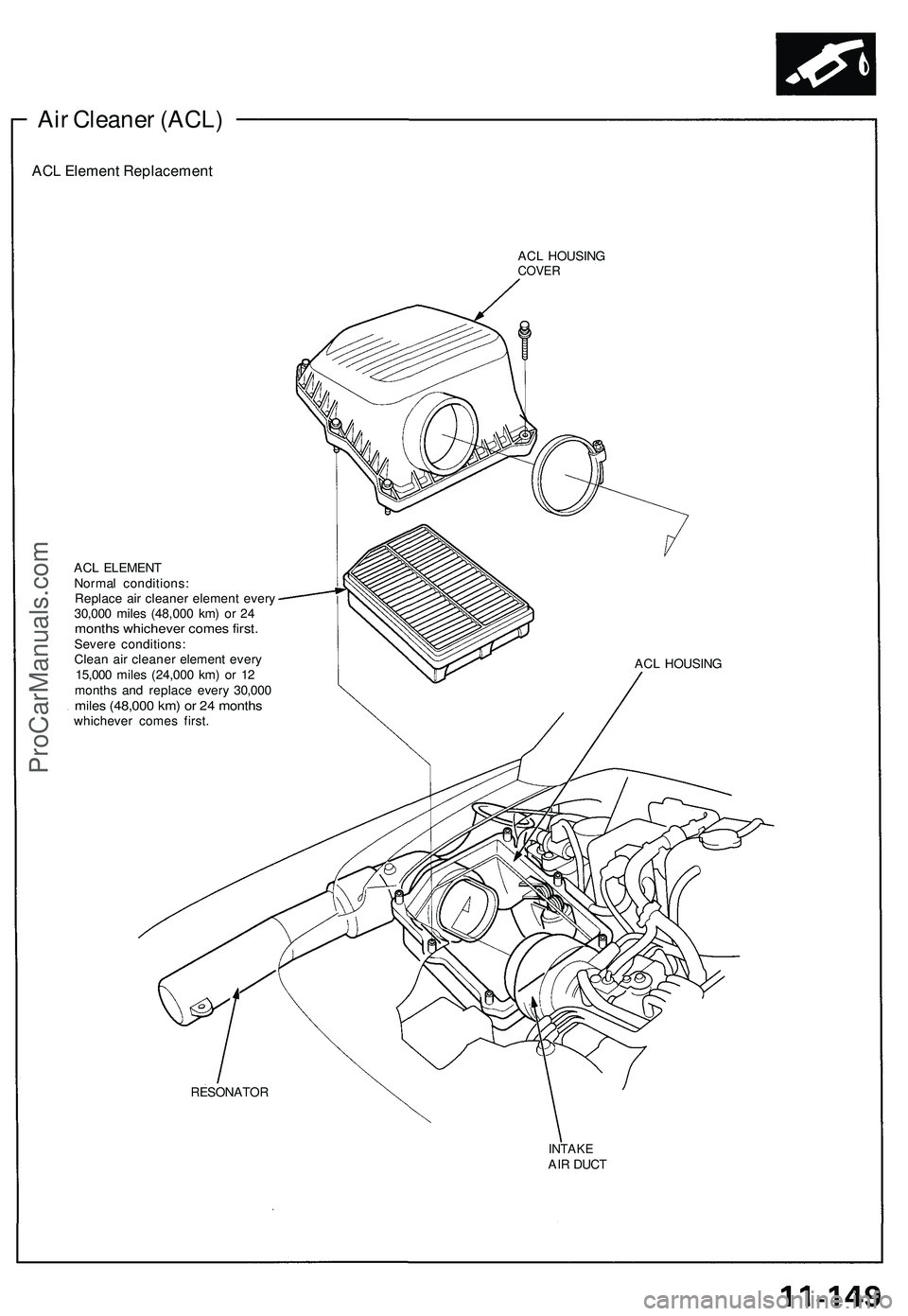
ACL Element Replacement
ACL HOUSING
COVER
ACL ELEMENT
Normal conditions:
Replace air cleaner element every
30,000 miles (48,000 km) or 24
months whichever comes first.
Severe conditions:
Clean air cleaner element every
15,000 miles (24,000 km) or 12
months and replace every 30,000
miles (48,000 km) or 24 months
whichever comes first.
ACL HOUSING
RESONATOR
INTAKE
AIR DUCTProCarManuals.com
Page 624 of 1503
Intake Air System
Throttle Cable ———
Inspection/Adjustment
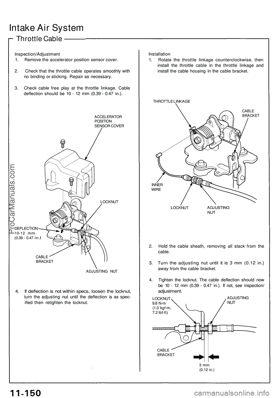
1. Remove the accelerator position sensor cover.
2. Check that the throttle cable operates smoothly with
no binding or sticking. Repair as necessary.
3. Check cable free play at the throttle linkage. Cable
deflection should be 10 - 12 mm (0.39 - 0.47 in.).
ACCELERATOR
POSITION
SENSOR COVER
DEFLECTION
10-12
mm
(0.39
-
0.47
in.
LOCKNUT
CABLE
BRACKET
ADJUSTING NUT
4. If deflection is not within specs, loosen the locknut,
turn the adjusting nut until the deflection is as spec-
ified then retighten the locknut.
Installation
1. Rotate the throttle linkage counterclockwise, then
install the throttle cable in the throttle linkage and
install the cable housing in the cable bracket.
THROTTLE LINKAGE
CABLE
BRACKET
INNER
WIRE
LOCKNUT
ADJUSTING
NUT
2. Hold the cable sheath, removing all slack from the
cable.
3. Turn the adjusting nut until it is 3 mm (0.12 in.)
away from the cable bracket.
4. Tighten the locknut. The cable deflection should now
be 10 - 12 mm (0.39 - 0.47 in.). If not, see inspection/
adjustment.
LOCKNUT
9.8 N-m
(1.0 kgf-m,
7.2 Ibf-ft)
ADJUSTING
NUT
CABLE
BRACKET
3 mm
(0.12 in.)ProCarManuals.com
Page 625 of 1503
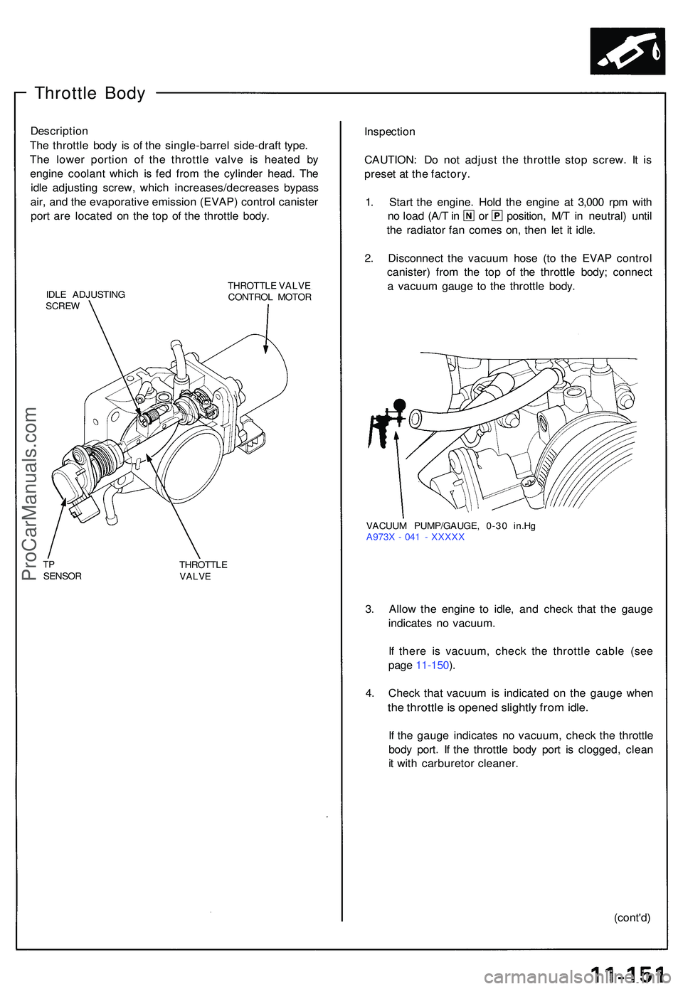
Throttle Bod y
Descriptio n
Th e throttl e bod y i s o f th e single-barre l side-draf t type .
Th e lowe r portio n o f th e throttl e valv e i s heate d b y
engine coolan t whic h i s fe d fro m th e cylinde r head . Th e
idl e adjustin g screw , whic h increases/decrease s bypas s
air , an d th e evaporativ e emissio n (EVAP ) contro l caniste r
por t ar e locate d o n th e to p o f th e throttl e body .
IDLE ADJUSTIN GSCREW
THROTTL E VALV E
CONTRO L MOTO R
TPSENSO R THROTTL
EVALVE
Inspectio n
CAUTION : D o no t adjus t th e throttl e sto p screw . I t i s
prese t a t th e factory .
1 . Star t th e engine . Hol d th e engine at 3,00 0 rp m wit h
no loa d (A/ T in o r position , M/ T i n neutral ) unti l
th e radiato r fa n come s on , the n le t i t idle .
2 . Disconnec t th e vacuu m hos e (t o th e EVA P contro l
canister ) fro m th e to p o f th e throttl e body ; connec t
a vacuu m gaug e t o th e throttl e body .
VACUU M PUMP/GAUGE , 0-3 0 in.H g
A973 X - 04 1 - XXXX X
3. Allo w th e engine to idle , an d chec k tha t th e gaug e
indicate s n o vacuum .
I f ther e i s vacuum , chec k th e throttl e cabl e (se e
pag e 11-150 ).
4 . Chec k tha t vacuu m is indicate d o n th e gaug e whe n
the throttl e is opene d slightl y fro m idle .
If th e gaug e indicate s n o vacuum , chec k th e throttl e
bod y port . I f th e throttl e bod y por t i s clogged , clea n
i t wit h carbureto r cleaner .
(cont'd)
ProCarManuals.com
Page 626 of 1503
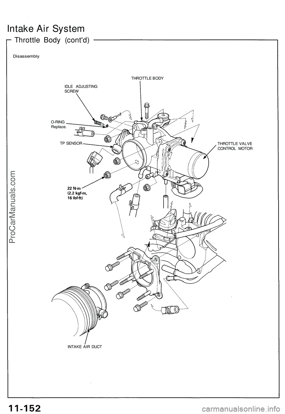
Intake Air System
Throttle Body (cont'd)
Disassembly
THROTTLE BODY
IDLE ADJUSTING
SCREW
O-RING
Replace.
INTAKE AIR DUCT
THROTTLE VALVE
CONTROL MOTOR
TP SENSORProCarManuals.com
Page 627 of 1503
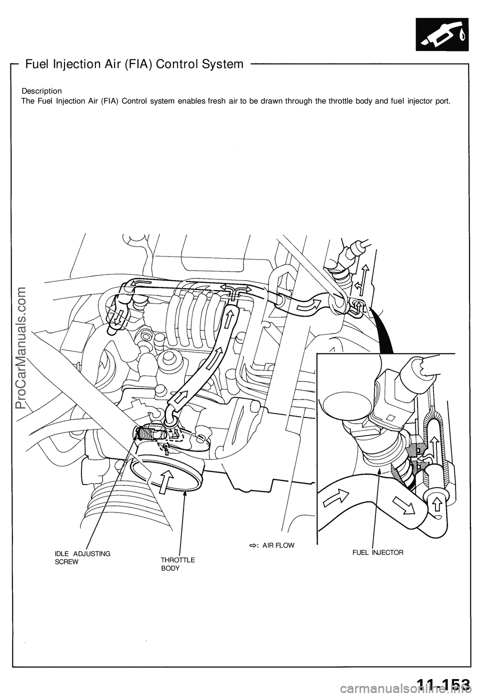
Description
The Fuel Injection Air (FIA) Control system enables fresh air to be drawn through the throttle body and fuel injector port.
IDLE ADJUSTING
SCREW
FUEL INJECTOR
THROTTLE
BODY
AIR FLOW
Fuel Injection Air (FIA) Control SystemProCarManuals.com
Page 628 of 1503
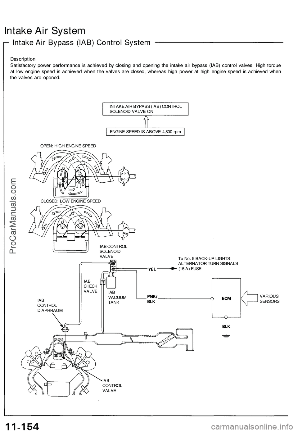
Intake Air System
Intake Air Bypass (IAB) Control System
Description
Satisfactory power performance is achieved by closing and opening the intake air bypass (IAB) control valves. High torque
at low engine speed is achieved when the valves are closed, whereas high power at high engine speed is achieved when
the valves are opened.
INTAKE AIR BYPASS (IAB) CONTROL
SOLENOID VALVE ON
ENGINE SPEED IS ABOVE 4,800 rpm
OPEN: HIGH ENGINE SPEED
CLOSED: LOW ENGINE SPEED
IAB CONTROL
SOLENOID
VALVE
To No. 5 BACK-UP LIGHTS
ALTERNATOR TURN SIGNALS
(15 A) FUSE
IAB
CONTROL
DIAPHRAGM
•IAB
CONTROL
VALVE
IAB
CHECK
VALVE
IAB
VACUUM
TANK
VARIOUS
SENSORSProCarManuals.com
Page 629 of 1503
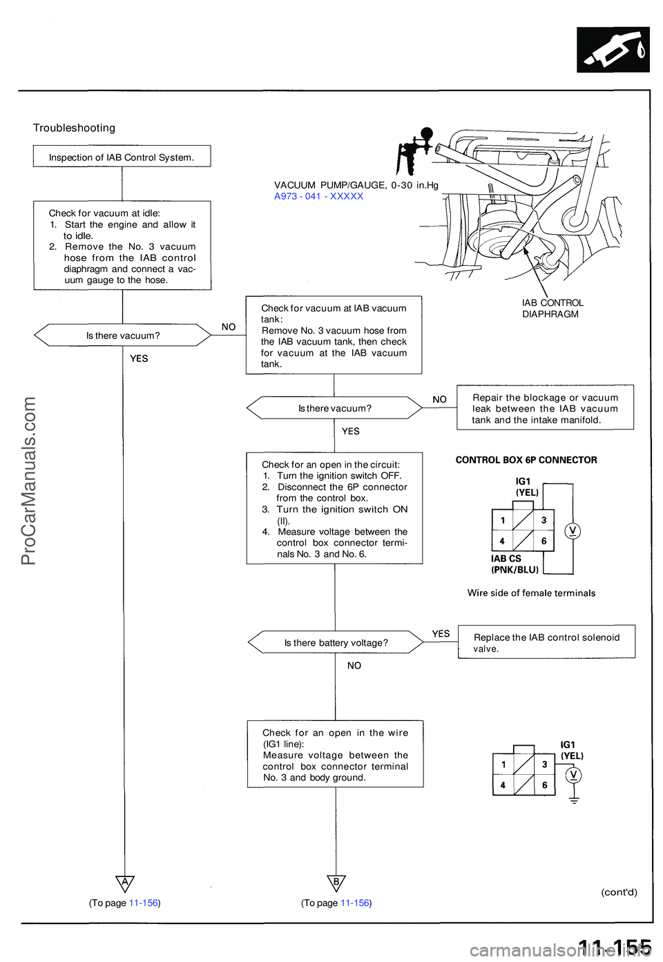
Troubleshooting
Inspection o f IA B Contro l System .
Chec k fo r vacuu m at idle :
1 . Star t th e engin e an d allo w it
to idle .2. Remov e th e No . 3 vacuu mhose fro m th e IA B contro ldiaphrag m an d connec t a vac -
uu m gaug e t o th e hose . VACUU
M PUMP/GAUGE , 0-3 0 in.H g
A97 3 - 04 1 - XXXX X
I s ther e vacuum ? Chec
k fo r vacuu m at IA B vacuu m
tank:Remov e No . 3 vacuu m hos e fro m
th e IA B vacuu m tank , the n chec k
fo r vacuu m a t th e IA B vacuu m
tank.
IAB CONTRO LDIAPHRAG M
Is ther e vacuum ?
Chec k fo r a n ope n in th e circuit :
1 . Tur n th e ignitio n switc h OFF .
2 . Disconnec t th e 6 P connecto r
fro m th e contro l box .
3. Tur n th e ignitio n switc h O N(II).4. Measur e voltag e betwee n th e
contro l bo x connecto r termi -
nal s No . 3 an d No . 6 .
I s ther e batter y voltage ? Replac
e th e IA B contro l solenoi d
valve.
Check fo r a n ope n i n th e wir e
(IG 1 line) :
Measur e voltag e betwee n th e
contro l bo x connecto r termina l
No . 3 an d bod y ground .
(T o pag e 11-156 )
(cont'd)(To pag e 11-156 ) Repai
r th e blockag e o r vacuu m
lea k betwee n th e IA B vacuu m
tan k an d th e intak e manifold .
ProCarManuals.com
Page 630 of 1503
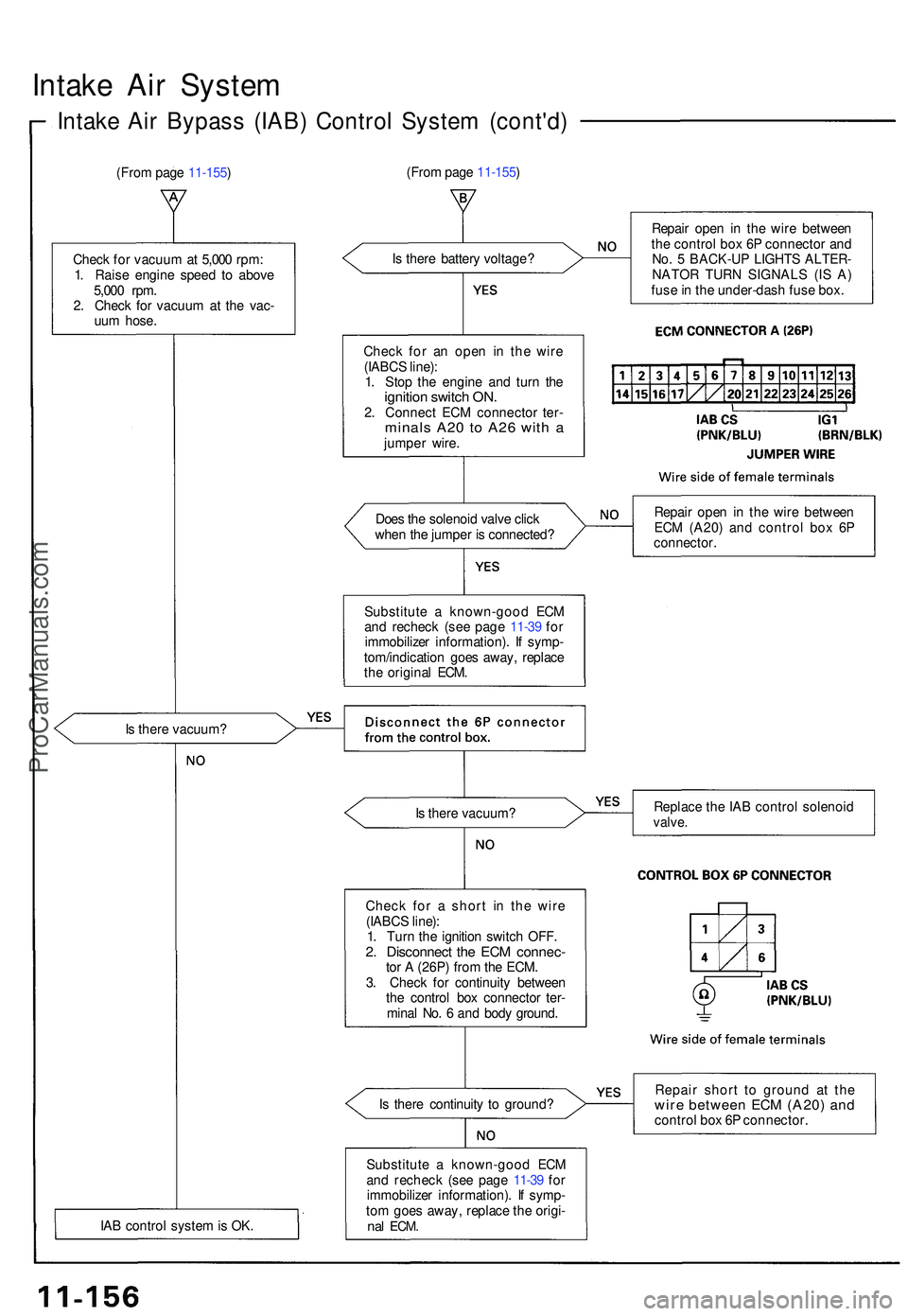
Intake Ai r Syste m
Intake Ai r Bypas s (IAB ) Contro l Syste m (cont'd )
(From pag e 11-155 )
Chec k fo r vacuu m at 5,00 0 rpm :
1 . Rais e engin e spee d t o abov e
5,00 0 rpm .
2 . Chec k fo r vacuu m a t th e vac -
uu m hose .
I s ther e vacuum ?
IA B contro l syste m is OK . I
s ther e batter y voltage ?
Chec k fo r a n ope n i n th e wir e
(IABC S line) :
1 . Sto p th e engin e an d tur n th e
ignitio n switc h ON .2. Connec t EC M connecto r ter -minal s A2 0 t o A2 6 wit h ajumpe r wire .
Doe s th e solenoi d valv e clic k
whe n th e jumpe r i s connected ?
Substitut e a known-goo d EC M
an d rechec k (se e pag e 11-3 9 fo r
immobilize r information) . I f symp -
tom/indicatio n goe s away , replac e
th e origina l ECM .
I s ther e vacuum ?
Chec k fo r a shor t i n th e wir e
(IABC S line) :
1 . Tur n th e ignitio n switc h OFF .
2. Disconnec t th e EC M connec -tor A (26P ) fro m th e ECM .
3 . Chec k fo r continuit y betwee n
th e contro l bo x connecto r ter -
mina l No . 6 an d bod y ground .
I s ther e continuit y t o ground ?
Substitut e a known-goo d EC M
an d rechec k (se e pag e 11-3 9 fo r
immobilize r information) . I f symp -
to m goe s away , replac e th e origi -
nal ECM .
Repai r ope n i n th e wir e betwee n
th e contro l bo x 6 P connecto r an d
No . 5 BACK-U P LIGHT S ALTER -
NATO R TUR N SIGNAL S (I S A )
fus e in th e under-das h fus e box .
Repai r ope n i n th e wir e betwee n
EC M (A20 ) an d contro l bo x 6 P
connector .
Replac e th e IA B contro l solenoi d
valve.
Repai r shor t t o groun d a t th ewir e betwee n EC M (A20 ) an dcontro l bo x 6 P connector .
(Fro
m pag e 11-155 )
ProCarManuals.com