ACURA NSX 1997 Service Repair Manual
Manufacturer: ACURA, Model Year: 1997,
Model line: NSX,
Model: ACURA NSX 1997
Pages: 1503, PDF Size: 57.08 MB
ACURA NSX 1997 Service Repair Manual
NSX 1997
ACURA
ACURA
https://www.carmanualsonline.info/img/32/56989/w960_56989-0.png
ACURA NSX 1997 Service Repair Manual
Trending: fuses, oil level, fuel type, start stop button, ignition, high beam, headlight bulb
Page 651 of 1503
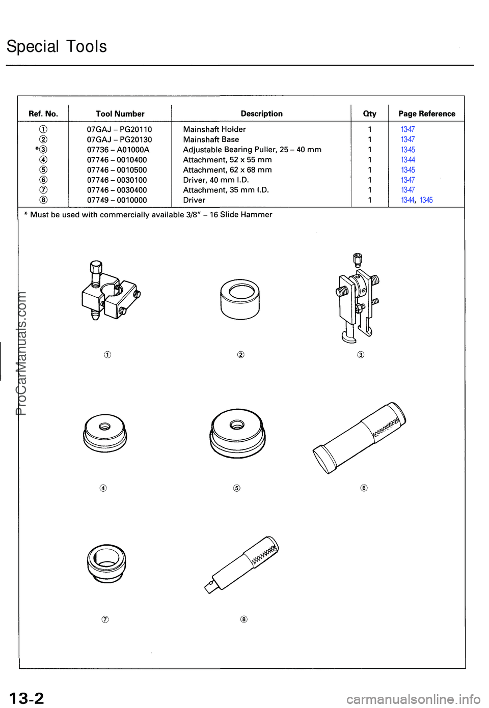
13-47
13-4 7
13-4 5
13-4 4
13-45
13-47
13-4 7
13-44 , 13-4 5
Specia l Tool s
ProCarManuals.com
Page 652 of 1503
Maintenance
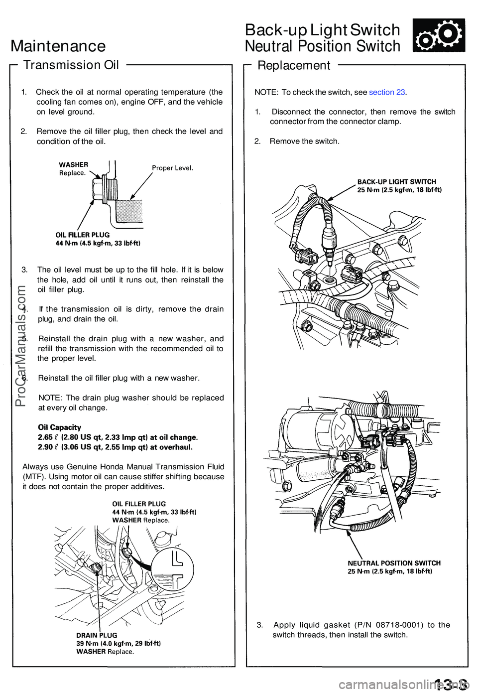
Transmissio n Oi l
1. Chec k th e oi l a t norma l operating temperatur e (th e
coolin g fa n come s on) , engin e OFF , an d th e vehicl e
o n leve l ground .
2 . Remov e th e oi l fille r plug , the n chec k th e leve l an d
conditio n o f th e oil .
3. Th e oi l leve l mus t b e u p t o th e fil l hole . I f i t i s belo w
th e hole , ad d oi l unti l i t run s out , the n reinstal l th e
oi l fille r plug .
4 . I f th e transmissio n oi l i s dirty , remov e th e drai n
plug , an d drai n th e oil .
5 . Reinstal l th e drai n plu g wit h a ne w washer , an d
refil l th e transmissio n wit h th e recommende d oi l t o
th e prope r level .
6 . Reinstal l th e oi l fille r plu g wit h a ne w washer .
NOTE : Th e drai n plu g washe r shoul d b e replace d
a t ever y oi l change .
Back-up Ligh t Switc h
Neutra l Positio n Switc h
Replacemen t
NOTE: T o chec k th e switch , se e sectio n 23 .
1 . Disconnec t th e connector , the n remov e th e switc h
connecto r fro m th e connecto r clamp .
2 . Remov e th e switch .
3 . Appl y liqui d gaske t (P/ N 0871 8-0001 ) t o th e
switc h threads , the n instal l th e switch .
Alway
s us e Genuin e Hond a Manua l Transmissio n Flui d
(MTF) . Usin g moto r oi l ca n caus e stiffe r shiftin g becaus e
i t doe s no t contai n th e prope r additives .
ProCarManuals.com
Page 653 of 1503
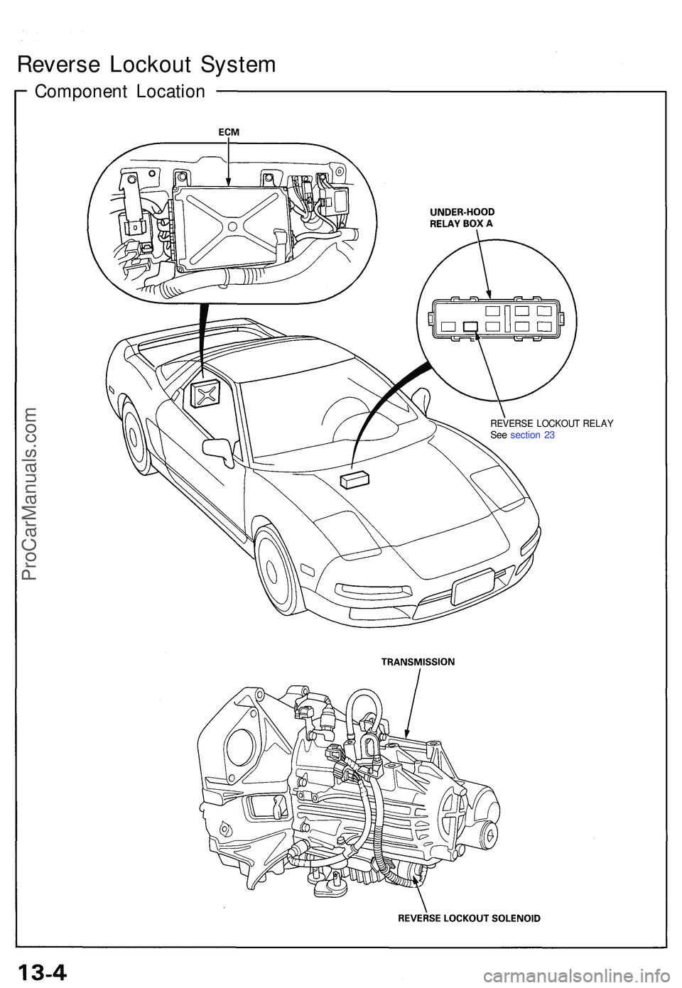
REVERSE LOCKOU T RELA YSee sectio n 2 3
Revers e Lockou t Syste m
Componen t Locatio n
ProCarManuals.com
Page 654 of 1503
Description
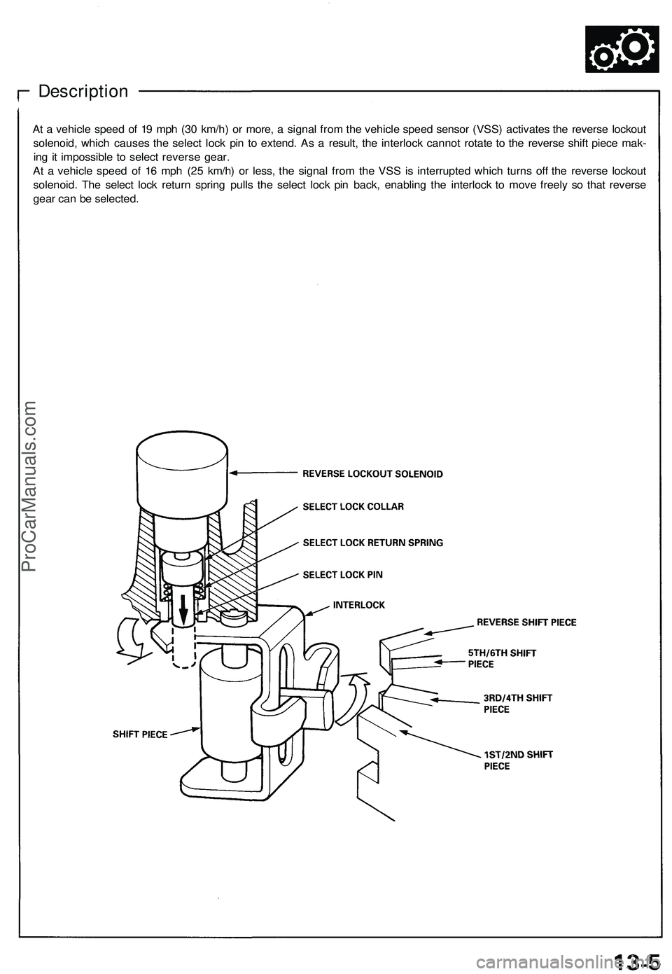
At a vehicle speed of 19 mph (30 km/h) or more, a signal from the vehicle speed sensor (VSS) activates the reverse lockout
solenoid, which causes the select lock pin to extend. As a result, the interlock cannot rotate to the reverse shift piece mak-
ing it impossible to select reverse gear.
At a vehicle speed of 16 mph (25 km/h) or less, the signal from the VSS is interrupted which turns off the reverse lockout
solenoid. The select lock return spring pulls the select lock pin back, enabling the interlock to move freely so that reverse
gear can be selected.ProCarManuals.com
Page 655 of 1503
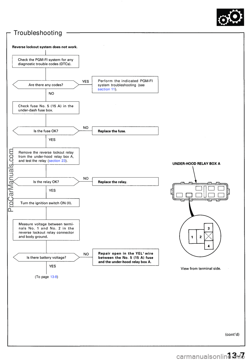
Troubleshooting
(To pag e 13-8 )
Perfor m th e indicate d PGM-F Isystem troubleshootin g (se e sectio n 11 ).
Remov e th e revers e lockou t rela y
fro m th e under-hoo d rela y bo x A ,
an d tes t th e rela y ( sectio n 23 ).
ProCarManuals.com
Page 656 of 1503
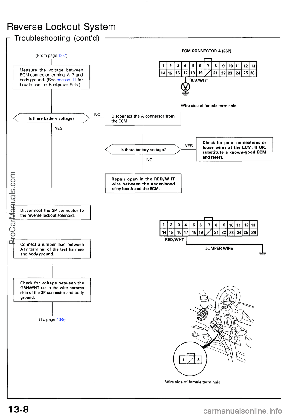
Reverse Lockou t Syste m
Troubleshootin g (cont'd )
(From pag e 13-7 )
Measur e th e voltag e betwee n
ECM connecto r termina l A1 7 an dbod y ground . (Se e sectio n 1 1 fo rhow to us e th e Backprov e Sets. )
(T o pag e 13-9 )
ProCarManuals.com
Page 657 of 1503
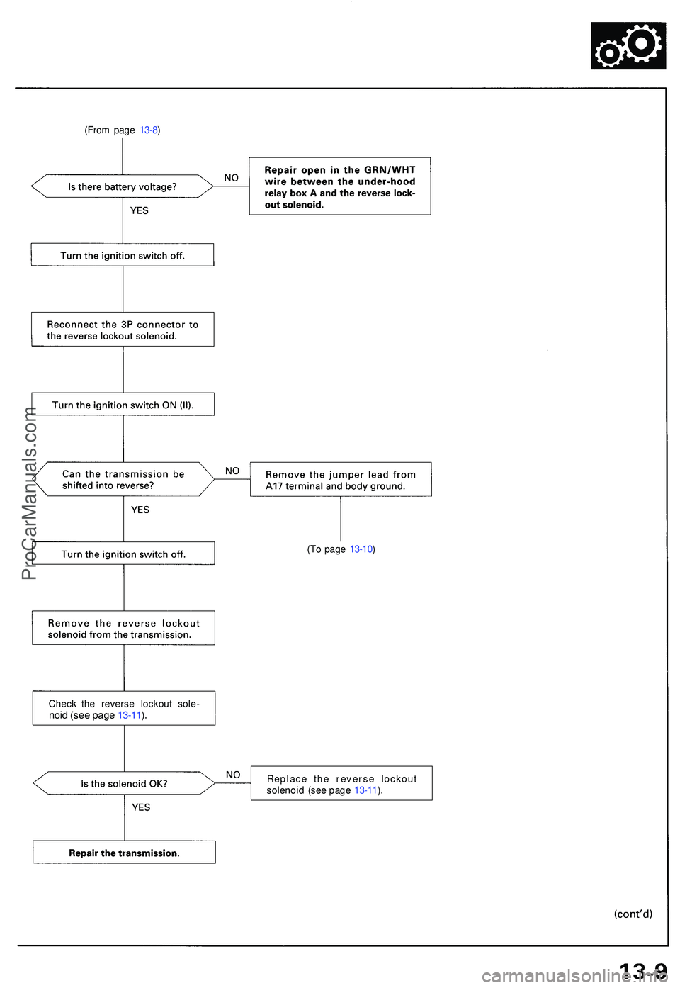
(From pag e 13-8 )
(To pag e 13-10 )
Chec k th e revers e lockou t sole -
noid (se e pag e 13-11 ).
Replac e th e revers e lockou t
solenoi d (se e pag e 13-11 ).
ProCarManuals.com
Page 658 of 1503
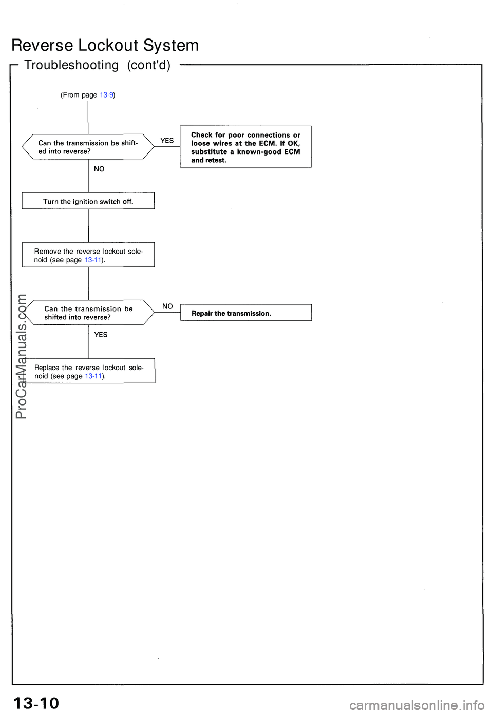
Reverse Lockou t Syste m
Troubleshootin g (cont'd )
(From pag e 13-9 )
Remov e th e revers e lockou t sole -
noi d (se e pag e 13-11 ).
Replac e th e revers e lockou t sole -
noi d (se e pag e 13-11 ).
ProCarManuals.com
Page 659 of 1503
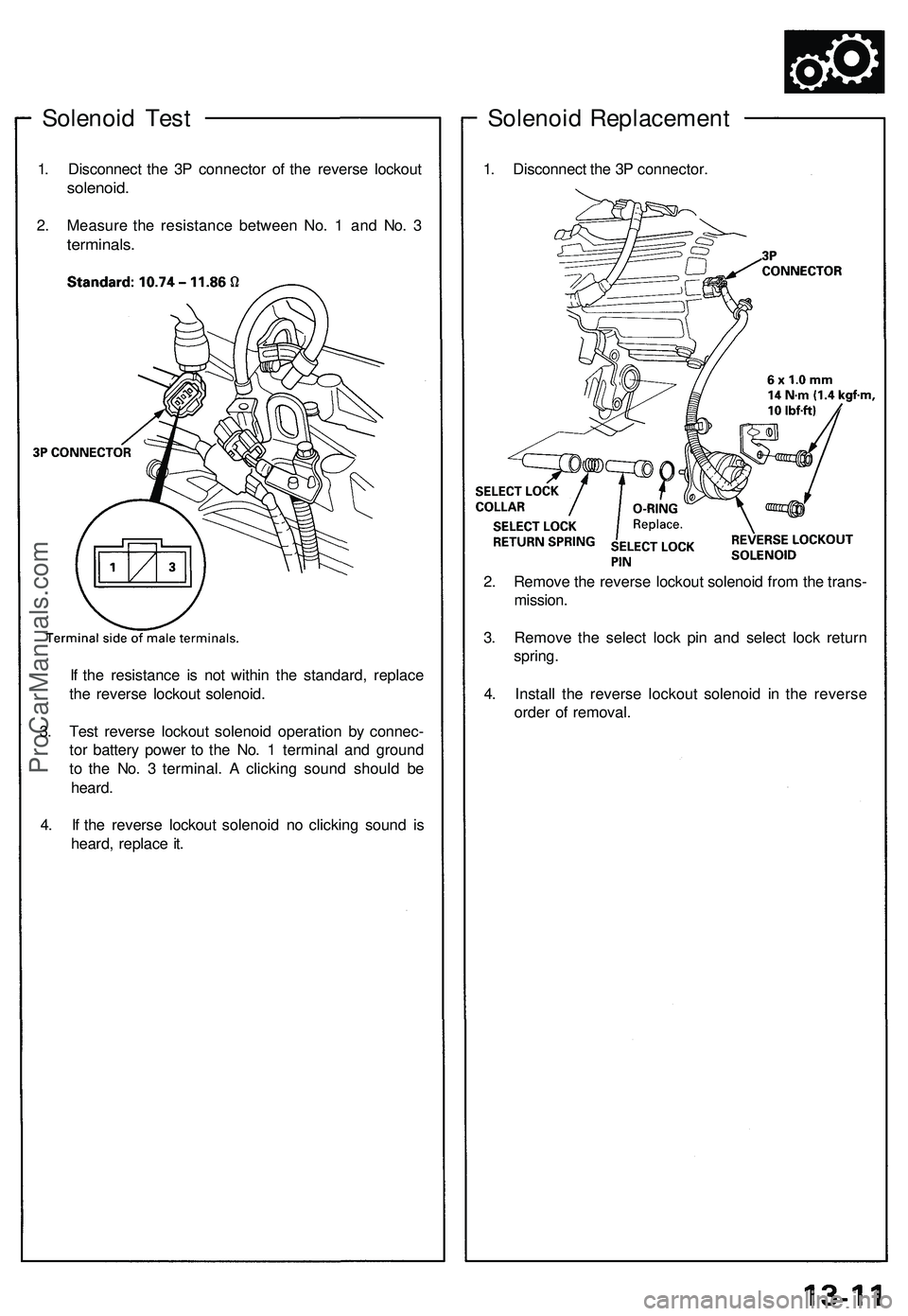
Solenoid Test
1. Disconnect the 3P connector of the reverse lockout
solenoid.
2. Measure the resistance between No. 1 and No. 3
terminals.
If the resistance is not within the standard, replace
the reverse lockout solenoid.
3. Test reverse lockout solenoid operation by connec-
tor battery power to the No. 1 terminal and ground
to the No. 3 terminal. A clicking sound should be
heard.
4. If the reverse lockout solenoid no clicking sound is
heard, replace it.
Solenoid Replacement
1. Disconnect the 3P connector.
2. Remove the reverse lockout solenoid from the trans-
mission.
3. Remove the select lock pin and select lock return
spring.
4. Install the reverse lockout solenoid in the reverse
order of removal.ProCarManuals.com
Page 660 of 1503
Transmission Assembl y
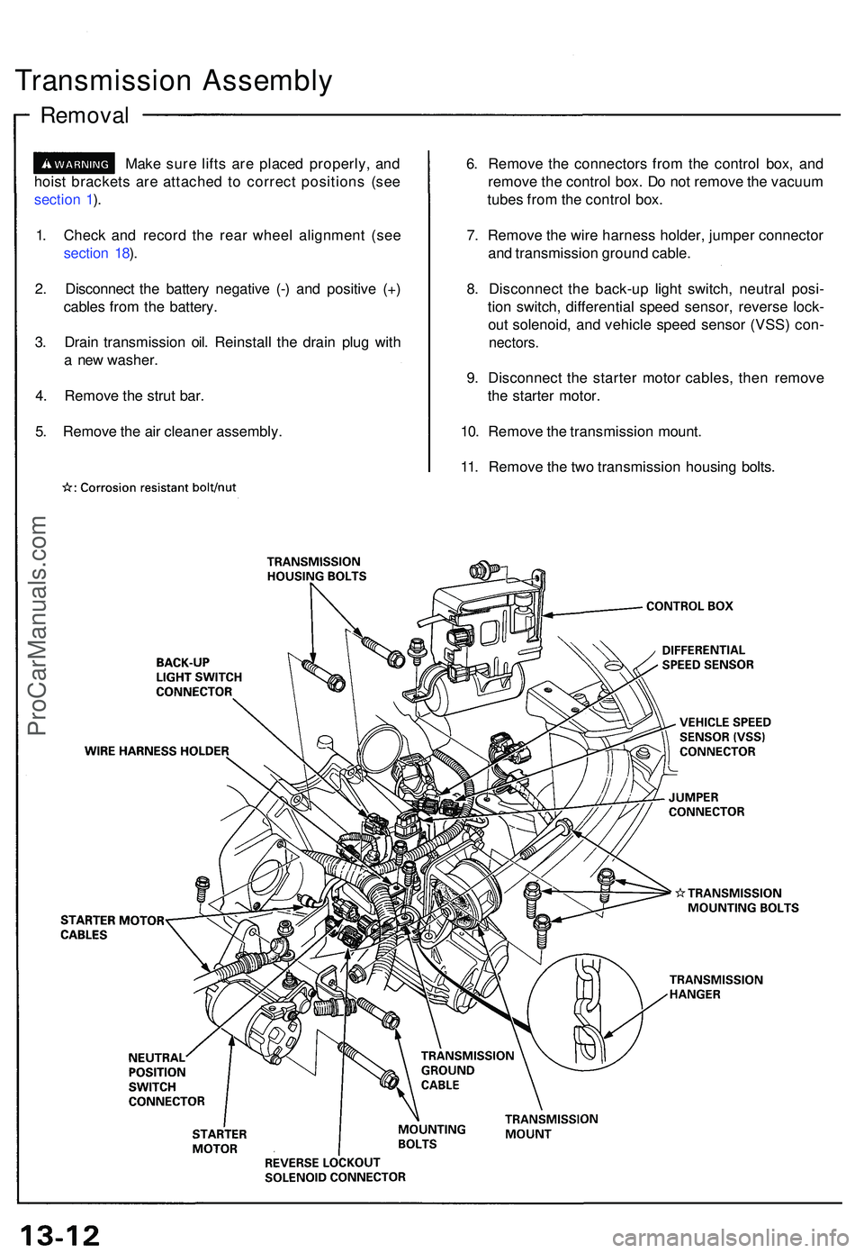
Removal
Make sur e lift s ar e place d properly , an d
hois t bracket s ar e attache d t o correc t position s (se e
sectio n 1 ).
1 . Chec k an d recor d th e rea r whee l alignmen t (se e
sectio n 18 ).
2 . Disconnec t th e batter y negativ e (- ) an d positiv e (+ )
cable s fro m th e battery .
3 . Drai n transmissio n oil . Reinstal l th e drai n plu g wit h
a ne w washer .
4 . Remov e th e stru t bar .
5 . Remov e th e ai r cleane r assembly . 6
. Remov e th e connector s fro m th e contro l box , an d
remov e th e contro l box . D o no t remov e th e vacuu m
tube s fro m th e contro l box .
7 . Remov e th e wir e harnes s holder , jumpe r connecto r
an d transmissio n groun d cable .
8 . Disconnec t th e back-u p ligh t switch , neutra l posi -
tio n switch , differentia l spee d sensor , revers e lock -
ou t solenoid , an d vehicl e spee d senso r (VSS ) con -
nectors .
9. Disconnec t th e starte r moto r cables , the n remov e
th e starte r motor .
10 . Remov e th e transmissio n mount .
11 . Remov e th e tw o transmissio n housin g bolts .
ProCarManuals.com
Trending: oil filter, clock, water pump, height, check engine, child restraint, parking sensors
