ACURA NSX 1997 Service Repair Manual
Manufacturer: ACURA, Model Year: 1997, Model line: NSX, Model: ACURA NSX 1997Pages: 1503, PDF Size: 57.08 MB
Page 601 of 1503
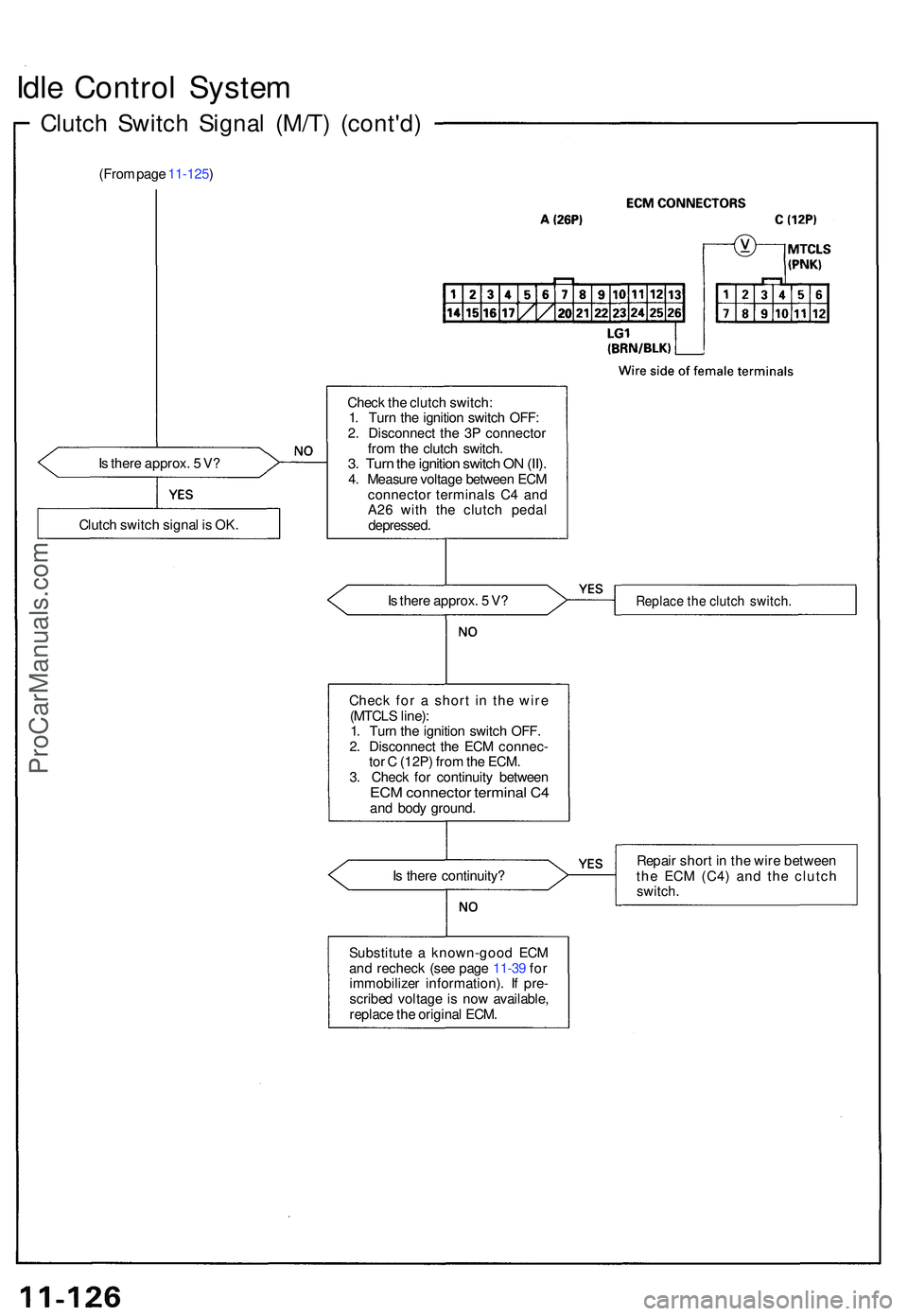
Idle Contro l Syste m
Clutch Switc h Signa l (M/T ) (cont'd )
(From pag e 11-125 )
I s ther e approx . 5 V ? Chec
k th e clutc h switch :
1 . Tur n th e ignitio n switc h OFF :
2 . Disconnec t th e 3 P connecto r
fro m th e clutc h switch .
3. Tur n th e ignitio n switc h O N (II) .4. Measur e voltag e betwee n EC M
connecto r terminal s C 4 an d
A2 6 wit h th e clutc h peda l
depressed .
I s ther e approx . 5 V ?
I s ther e continuity ?
Substitut e a known-goo d EC M
an d rechec k (se e pag e 11-3 9 fo r
immobilize r information) . I f pre -
scribe d voltag e i s no w available ,
replac e th e origina l ECM .
Replac e th e clutc h switch .
Repair shor t i n th e wir e betwee n
th e EC M (C4 ) an d th e clutc h
switch.
Clutch switc h signa l i s OK .
Check fo r a shor t i n th e wir e
(MTCL S line) :
1 . Tur n th e ignitio n switc h OFF .
2 . Disconnec t th e EC M connec -
to r C (12P ) fro m th e ECM .
3 . Chec k fo r continuit y betwee n
ECM connecto r termina l C 4an d bod y ground .
ProCarManuals.com
Page 602 of 1503
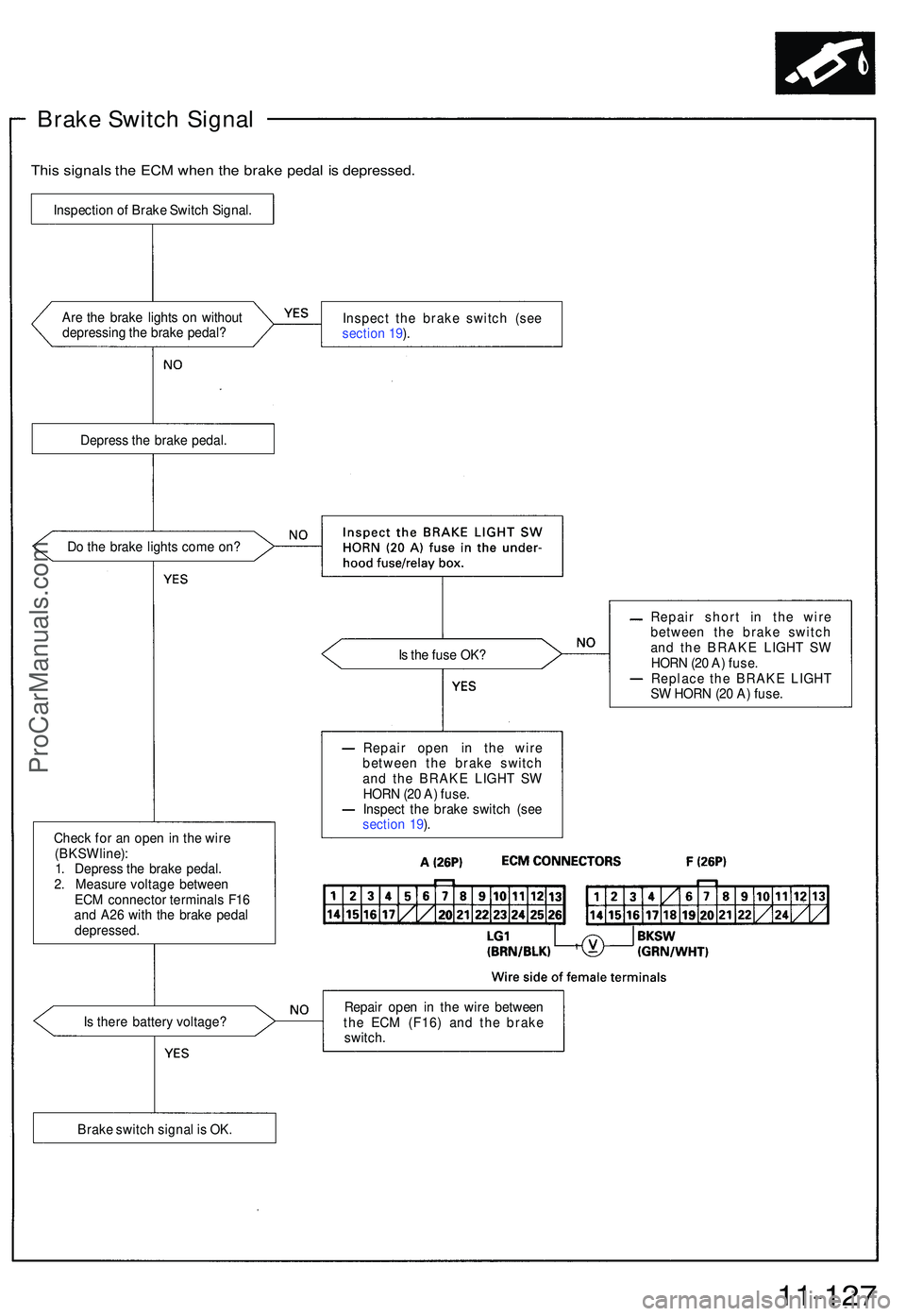
Brake Switc h Signa l
This signal s th e EC M whe n th e brak e peda l i s depressed .
Are th e brak e light s o n withou t
depressin g th e brak e pedal ? Inspec
t th e brak e switc h (se e
sectio n 19 ).
Depres s th e brak e pedal .
D o th e brak e light s com e on ?
Is th e fus e OK ?
Chec k fo r a n ope n in th e wir e
(BKS W line) :
1 . Depres s th e brak e pedal .
2 . Measur e voltag e betwee n
EC M connecto r terminal s F1 6
an d A2 6 wit h th e brak e peda l
depressed . Repai
r shor t i n th e wir e
betwee n th e brak e switc h
an d th e BRAK E LIGH T S W
HOR N (2 0 A ) fuse .
Replac e th e BRAK E LIGH T
S W HOR N (2 0 A ) fuse .
I s ther e batter y voltage ? Repai
r ope n i n th e wir e betwee n
th e EC M (F16 ) an d th e brak e
switch .
11-127
Inspectio n o f Brak e Switc h Signal .
Brak e switc h signa l i s OK . Repai
r ope n i n th e wir e
betwee n th e brak e switc h
an d th e BRAK E LIGH T S W
HOR N (2 0 A ) fuse .
Inspec t th e brak e switc h (se e
sectio n 19 ).
ProCarManuals.com
Page 603 of 1503
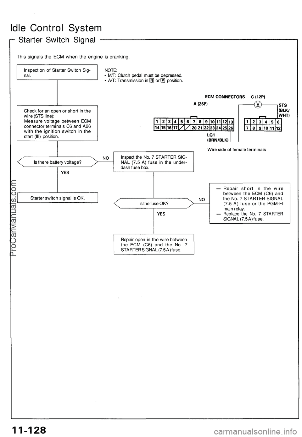
Idle Control System
Starter Switch Signal
This signals the ECM when the engine is cranking.
NOTE:
• M/T: Clutch pedal must be depressed.
• A/T: Transmission in or position.
Is there battery voltage?
Is the fuse OK?
Repair short in the wire
between the ECM (C6) and
the No. 7 STARTER SIGNAL
(7.5 A) fuse or the PGM-FI
main relay.
Replace the No. 7 STARTER
SIGNAL (7.5 A) fuse.
Inspection of Starter Switch Sig-
nal.
Check for an open or short in the
wire (STS line):
Measure voltage between ECM
connector terminals C6 and A26
with the ignition switch in the
start (III) position.
Starter switch signal is OK.
Repair open in the wire between
the ECM
(C6)
and the No. 7
STARTER SIGNAL (7.5 A) fuse.
Inspect the No. 7 STARTER SIG-
NAL (7.5 A) fuse in the under-
dash fuse box.ProCarManuals.com
Page 604 of 1503
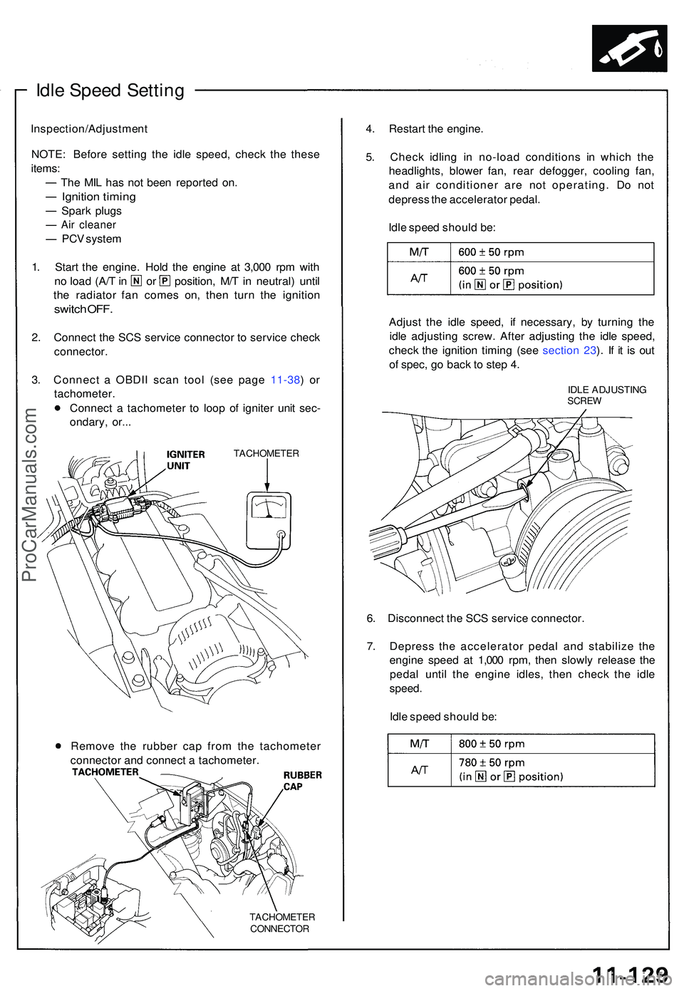
Idle Spee d Settin g
Inspection/Adjustmen t
NOTE : Befor e settin g th e idl e speed , chec k th e thes e
items :
Th e MI L ha s no t bee n reporte d on .
Ignitio n timin g
Spark plug s
Air cleane r
PCV syste m
1 . Star t th e engine . Hol d th e engin e a t 3,00 0 rp m wit h
no loa d (A/ T in o r position , M/ T in neutral ) unti l
th e radiato r fa n come s on , the n tur n th e ignitio n
switch OFF .
2. Connec t th e SC S servic e connecto r t o servic e chec k
connector .
3. Connec t a OBDI I sca n too l (se e pag e 11-38 ) o r
tachometer .
Connec t a tachomete r t o loo p o f ignite r uni t sec -
ondary , or.. .
TACHOMETE R
TACHOMETE R
CONNECTOR
4. Restar t th e engine .
5 . Chec k idlin g i n no-loa d condition s i n whic h th e
headlights , blowe r fan , rea r defogger , coolin g fan ,
an d ai r conditione r ar e no t operating . D o no t
depres s th e accelerato r pedal .
Idl e spee d shoul d be :
Adjus t th e idl e speed , i f necessary , b y turnin g th e
idl e adjustin g screw . Afte r adjustin g th e idl e speed ,
chec k th e ignitio n timin g (se e sectio n 23 ). I f i t i s ou t
o f spec , g o bac k t o ste p 4 .
IDL E ADJUSTIN GSCREW
6. Disconnec t th e SC S servic e connector .
7 . Depres s th e accelerato r peda l an d stabiliz e th e
engin e spee d a t 1,00 0 rpm , the n slowl y releas e th e
peda l unti l th e engin e idles , the n chec k th e idl e
speed .
Idle spee d shoul d be :
Remov e th e rubbe r ca p fro m th e tachomete r
connecto r an d connec t a tachometer .
ProCarManuals.com
Page 605 of 1503
Fuel Suppl y Syste m
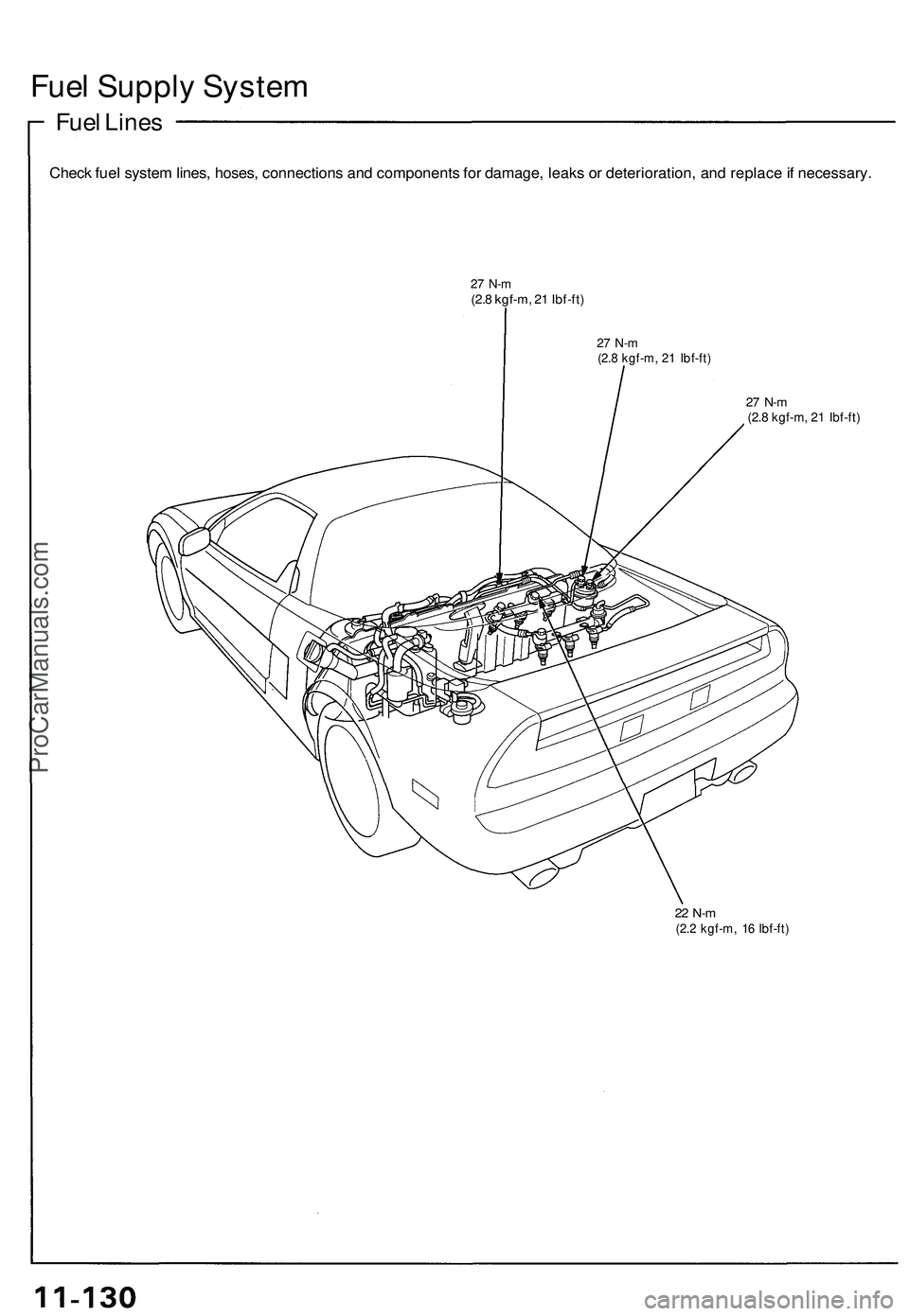
Fuel Line s
Chec k fue l syste m lines , hoses , connection s an d component s fo r damage , leak s o r deterioration , an d replac e if necessary .
27 N- m(2.8 kgf-m , 2 1 Ibf-ft )
27 N- m(2.8 kgf-m , 2 1 Ibf-ft )
27 N- m (2. 8 kgf-m , 2 1 Ibf-ft )
22 N- m(2.2 kgf-m , 1 6 Ibf-ft )
ProCarManuals.com
Page 606 of 1503
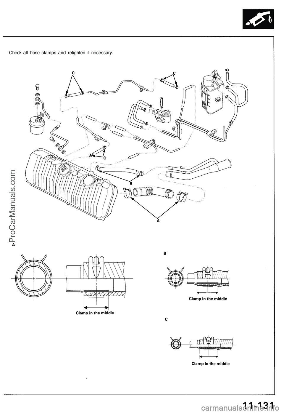
Check all hose clamps and retighten if necessary.ProCarManuals.com
Page 607 of 1503
Fuel Supply System
System Description
The fuel supply system consists of a fuel tank, in-tank
high-pressure fuel pump, fuel pump relay, fuel pump
resistor PGM-FI main relay, fuel filter, fuel pressure regu-
lator, fuel injectors, injector resistor (A/T), and fuel deliv-
ery and return lines. This system delivers pressure-regu-
lated fuel to the fuel injectors and cuts the fuel delivery
when the engine is not running.ProCarManuals.com
Page 608 of 1503
Fuel Pressur e
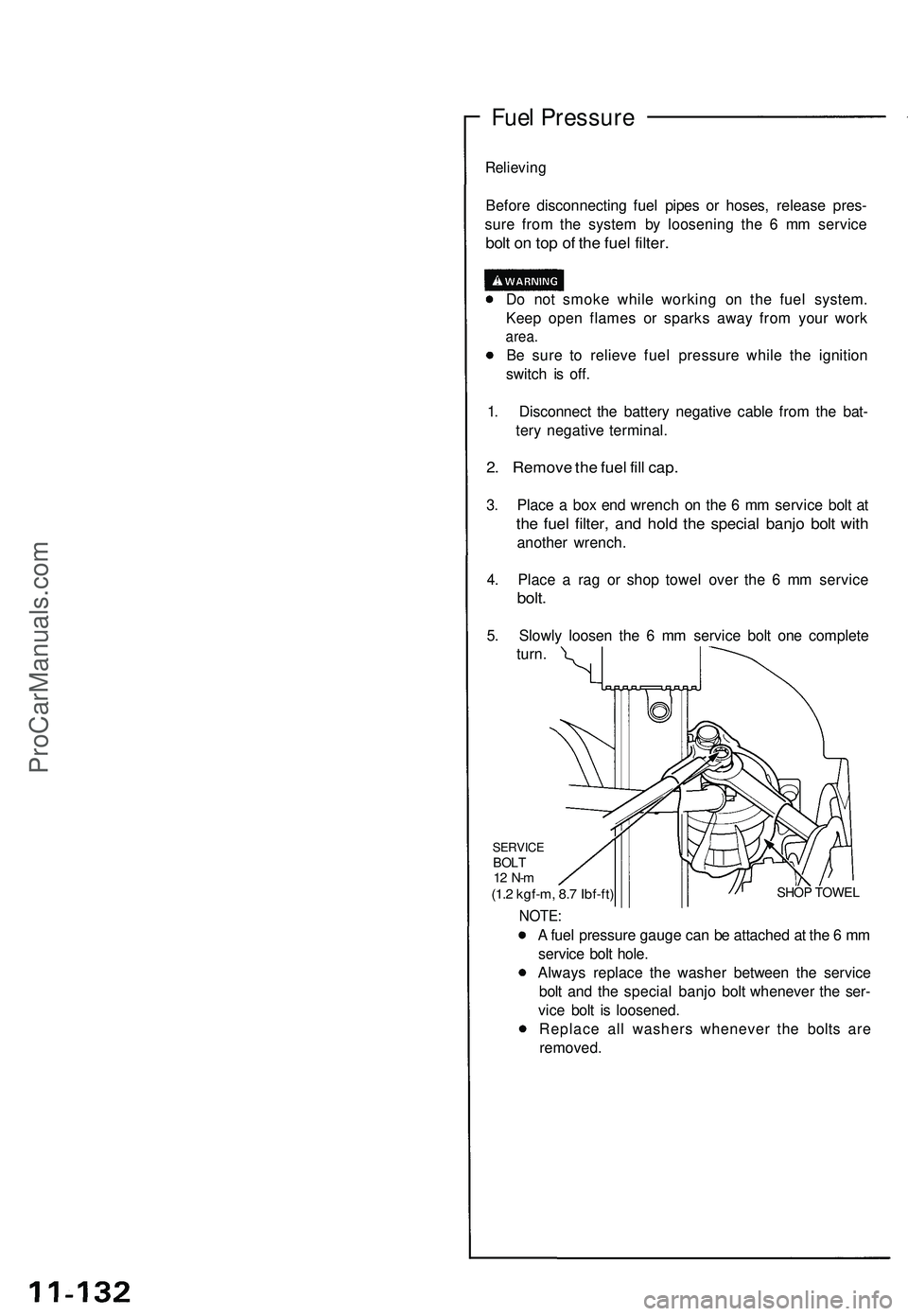
Relieving
Before disconnectin g fue l pipe s o r hoses , releas e pres -
sur e fro m th e syste m b y loosenin g th e 6 m m servic e
bolt o n to p o f th e fue l filter .
Do no t smok e whil e workin g o n th e fue l system .
Kee p ope n flame s o r spark s awa y fro m you r wor k
area.
Be sur e t o reliev e fue l pressur e whil e th e ignitio n
switc h i s off .
1 . Disconnec t th e batter y negativ e cabl e fro m th e bat -
ter y negativ e terminal .
2. Remov e th e fue l fil l cap .
3. Plac e a bo x en d wrenc h o n th e 6 m m servic e bol t a t
the fue l filter , an d hol d th e specia l banj o bol t wit h
anothe r wrench .
4 . Plac e a ra g o r sho p towe l ove r th e 6 m m servic e
bolt.
5. Slowl y loose n th e 6 m m servic e bol t on e complet e
turn .
SHO P TOWE L
SERVIC EBOLT12 N- m(1.2 kgf-m , 8. 7 Ibf-ft )
NOTE :
A fue l pressur e gaug e ca n b e attache d a t th e 6 m m
servic e bol t hole .
Alway s replac e th e washe r betwee n th e servic e
bol t an d th e specia l banj o bol t wheneve r th e ser -
vic e bol t i s loosened .
Replac e al l washer s wheneve r th e bolt s ar e
removed .
ProCarManuals.com
Page 609 of 1503
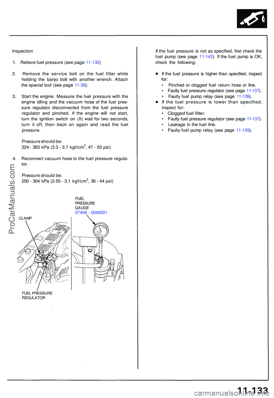
Inspection
1 . Reliev e fue l pressur e (se e pag e 11-132 )
2 . Remov e th e servic e bol t o n th e fue l filte r whil e
holdin g th e banj o bol t wit h anothe r wrench . Attac h
th e specia l too l (se e pag e 11-38 ).
3 . Star t th e engine . Measur e th e fue l pressur e wit h th e
engin e idlin g an d th e vacuu m hos e o f th e fue l pres -
sur e regulato r disconnecte d fro m th e fue l pressur e
regulato r an d pinched . I f th e engin e wil l no t start ,
tur n th e ignitio n switc h o n (II ) wai t fo r tw o seconds ,
tur n i t off , the n bac k o n agai n an d rea d th e fue l
pressure .
Pressure shoul d be :
32 4 - 36 3 kP a (3. 3 - 3. 7 kgf/cm2, 4 7 - 5 3 psi )
4 . Reconnec t vacuu m hos e to th e fue l pressur e regula -
tor.
Pressur e shoul d be :
25 0 - 30 4 kP a (2.5 5 - 3. 1 kgf/cm2, 3 6 - 4 4 psi )
FUE LPRESSUR EGAUGE07406 - 004000 1
CLAMP
FUEL PRESSUR EREGULATO R
If th e fue l pressur e i s no t a s specified , firs t chec k th e
fue l pum p (se e pag e 11-142 ). I f th e fue l pum p is OK ,
chec k th e following :
I f th e fue l pressur e i s highe r tha n specified , inspec t
for:
• Pinche d o r clogge d fue l retur n hos e o r line .
• Fault y fue l pressur e regulato r (se e pag e 11-137 ).
• Fault y fue l pum p rela y (se e pag e 11-139 ).
If th e fue l pressur e i s lowe r tha n specified ,
inspect for :
• Clogge d fue l filter .
• Fault y fue l pressur e regulato r (se e pag e 11-137 ).
• Leakag e i n th e fue l line .
• Fault y fue l pum p rela y (se e pag e 11-139 ).
ProCarManuals.com
Page 610 of 1503
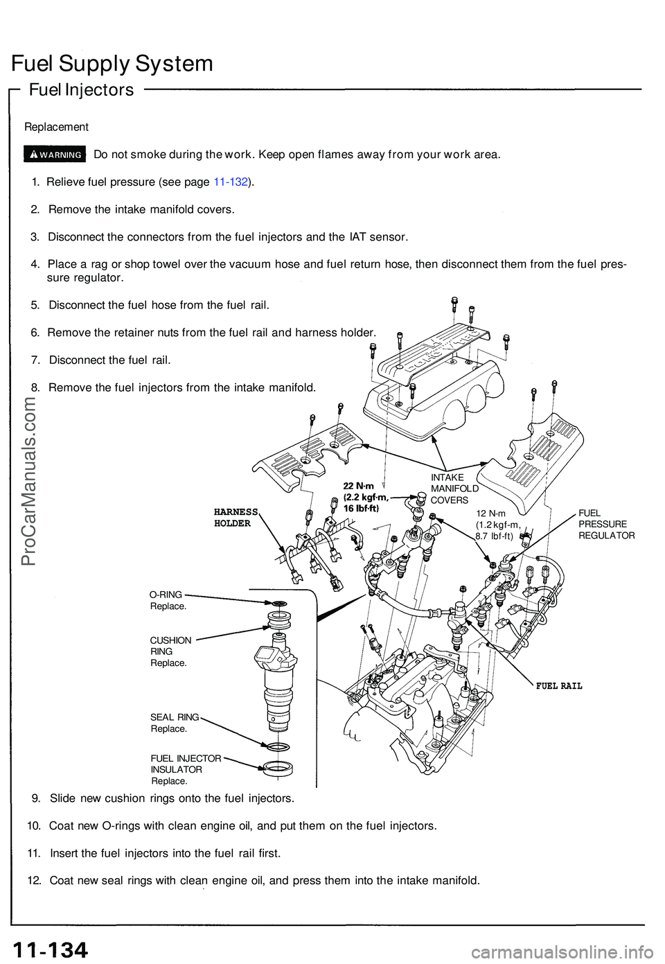
Fuel Suppl y Syste m
Fuel Injector s
Replacemen t
Do no t smok e durin g th e work . Kee p ope n flame s awa y fro m you r wor k area .
1 . Reliev e fue l pressur e (se e pag e 11-132 ).
2 . Remov e th e intak e manifol d covers .
3 . Disconnec t th e connector s fro m th e fue l injector s an d th e IA T sensor .
4 . Plac e a ra g o r sho p towe l ove r th e vacuu m hos e an d fue l retur n hose , the n disconnec t the m fro m th e fue l pres -
sur e regulator .
5 . Disconnec t th e fue l hos e fro m th e fue l rail .
6 . Remov e th e retaine r nut s fro m th e fue l rai l an d harnes s holder .
7 . Disconnec t th e fue l rail .
8 . Remov e th e fue l injector s fro m th e intak e manifold .
INTAKEMANIFOL DCOVERS
12 N- m(1.2 kgf-m ,8.7 Ibf-ft )
FUELPRESSUR EREGULATO R
O-RINGReplace .
CUSHIO N
RIN G
Replace .
SEAL RIN GReplace .
FUEL INJECTO R
INSULATO R
Replace.
9. Slid e ne w cushio n ring s ont o th e fue l injectors .
10 . Coa t ne w O-ring s wit h clea n engin e oil , an d pu t the m o n th e fue l injectors .
11 . Inser t th e fue l injector s int o th e fue l rai l first .
12 . Coa t ne w sea l ring s wit h clea n engin e oil , an d pres s the m int o th e intak e manifold .
FUEL RAI L
HARNES SHOLDER
ProCarManuals.com