ACURA RL KA9 1996 Service Repair Manual
Manufacturer: ACURA, Model Year: 1996, Model line: RL KA9, Model: ACURA RL KA9 1996Pages: 1954, PDF Size: 61.44 MB
Page 1371 of 1954
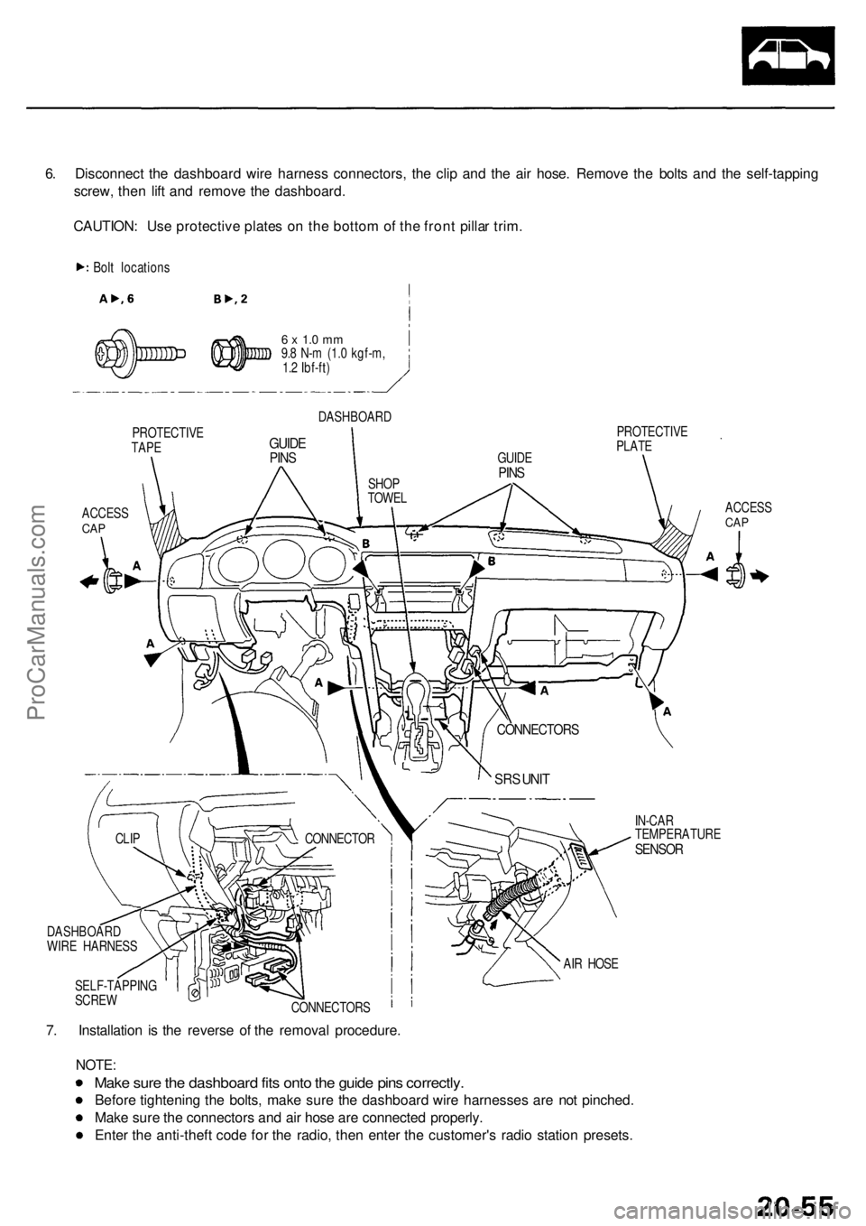
6. Disconnec t th e dashboar d wir e harnes s connectors , th e cli p an d th e ai r hose . Remov e th e bolt s an d th e self-tappin g
screw , the n lif t an d remov e th e dashboard .
CAUTION : Us e protectiv e plate s o n th e botto m of th e fron t pilla r trim .
Bolt location s
PROTECTIV E
TAPE
ACCES SCAP
6 x 1. 0 m m9.8 N- m (1. 0 kgf-m ,
1. 2 Ibf-ft )
DASHBOAR D
GUIDEPINS
PROTECTIV E
PLAT E
ACCESS
CAP
IN-CA R
TEMPERATUR E
SENSOR
7. Installatio n i s th e revers e o f th e remova l procedure .
NOTE:
Make sur e th e dashboar d fit s ont o th e guid e pin s correctly .
Before tightenin g th e bolts , mak e sur e th e dashboar d wir e harnesse s ar e no t pinched .
Mak e sur e th e connector s an d ai r hos e ar e connecte d properly .
Ente r th e anti-thef t cod e fo r th e radio , the n ente r th e customer' s radi o statio n presets .
SELF-TAPPIN G
SCRE W
CONNECTORS AI
R HOS E
CONNECTO
R
CLIP
DASHBOAR D
WIR E HARNES S
SRS UNI T
CONNECTOR S
GUIDEPINSSHO P
TOWE L
ProCarManuals.com
Page 1372 of 1954
Seats
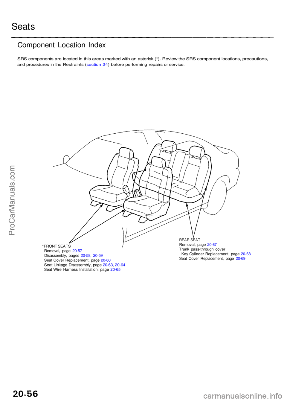
Componen t Locatio n Inde x
SRS component s ar e locate d in thi s area s marke d wit h a n asteris k (*) . Revie w th e SR S componen t locations , precautions ,
and procedure s i n th e Restraint s ( sectio n 24 ) befor e performin g repair s o r service .
*FRONT SEAT S
Removal , pag e 20-5 7
Disassembly , page s 20-58 , 20-5 9
Sea t Cove r Replacement , pag e 20-6 0
Seat Linkag e Disassembly , pag e 20-63 , 20-6 4Seat Wir e Harnes s Installation , pag e 20-6 5
REA R SEA TRemoval , pag e 20-6 7
Trun k pass-throug h cove r
Ke y Cylinde r Replacement , pag e 20-6 8
Sea t Cove r Replacement , pag e 20-6 9
ProCarManuals.com
Page 1373 of 1954
Front Sea t
Remova l
SRS component s ar e locate d i n thi s area . Revie w th e
SR S componen t locations , precautions , an d procedure s
i n th e Restraint s ( sectio n 24 ) befor e performin g repair s
o r service .
CAUTION : Whe n pryin g wit h a flat-ti p screwdriver , wra p
i t wit h protectiv e tap e t o preven t damage .
NOTE : Tak e car e no t t o scratc h th e sea t cover s an d body .
1 . Mak e sur e yo u hav e th e anti-thef t cod e fo r th e
radio , the n writ e dow n th e frequencie s fo r th e pre -
set buttons .
2. Disconnec t th e negativ e batter y cable , an d wai t a t
leas t 3 minute s befor e beginnin g work .
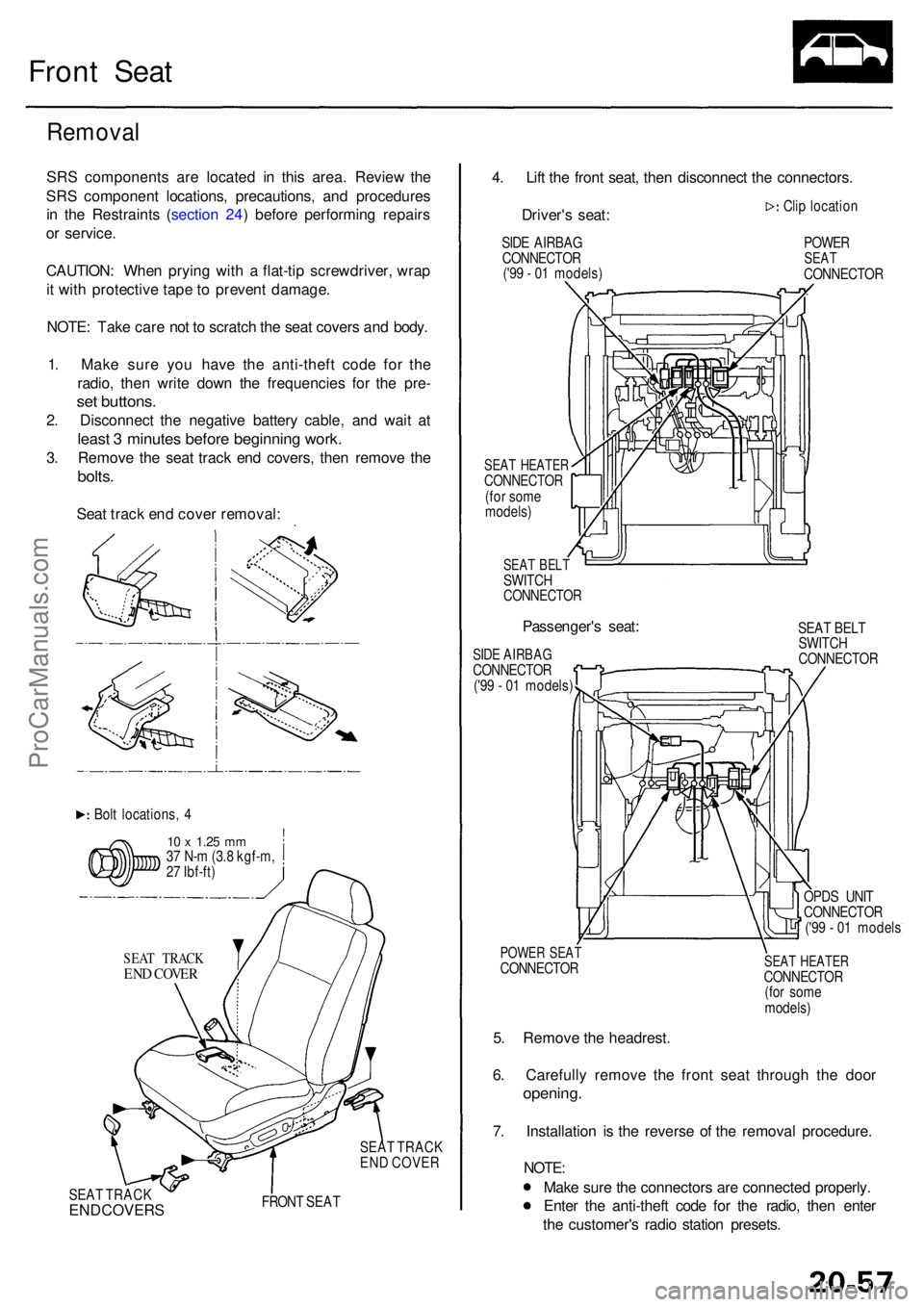
3. Remov e th e sea t trac k en d covers , the n remov e th e
bolts .
Seat trac k en d cove r removal :
Bolt locations , 4
1 0 x 1.2 5 mm37 N- m (3. 8 kgf-m ,
2 7 Ibf-ft )
SEA T TRAC K
END COVE R
SEAT TRAC K
EN D COVE R
SEA T TRAC K
END COVER S FRON T SEA T
4. Lif t th e fron t seat , the n disconnec t th e connectors .
Driver' s seat :
SIDE AIRBA G
CONNECTO R
('9 9 - 0 1 models )
SEAT HEATE RCONNECTO R(for som e
models )
SEAT BEL TSWITC HCONNECTO R
Passenger's seat :
SIDE AIRBA GCONNECTO R('99 - 0 1 models ) Cli
p locatio n
POWERSEATCONNECTO R
SEA T BEL T
SWITC H
CONNECTO R
POWER SEA TCONNECTO R
5. Remov e th e headrest .
6 . Carefull y remov e th e fron t sea t throug h th e doo r
opening .
7. Installatio n i s th e revers e o f th e remova l procedure .
NOTE:
Make sur e th e connector s ar e connecte d properly .
Ente r th e anti-thef t cod e fo r th e radio , the n ente r
th e customer' s radi o statio n presets .
SEAT HEATE RCONNECTO R
(fo r som e
models )
OPD
S UNI T
CONNECTO R
('9 9 - 0 1 model s
ProCarManuals.com
Page 1374 of 1954
Front Sea t
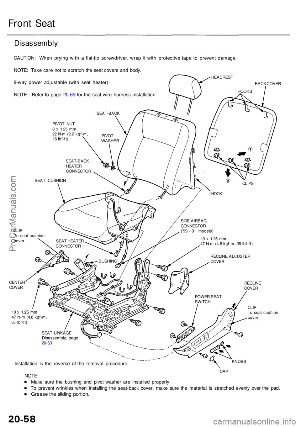
Disassembl y
CAUTION: Whe n pryin g wit h a flat-ti p screwdriver , wra p i t wit h protectiv e tap e t o preven t damage .
NOTE : Tak e car e no t t o scratc h th e sea t cover s an d body .
HEADRES T8-way powe r adjustabl e (wit h sea t heater) :
NOTE : Refe r t o pag e 20-6 5 fo r th e sea t wir e harnes s installation .BACK COVE R
SEAT-BAC K
PIVOT NU T8 x 1.2 5 mm22 N- m (2. 2 kgf-m ,
1 6 Ibf-ft )
SEA T CUSHIO N
CLIPTo sea t cushio n
cover .
CENTE RCOVER
10 x 1.2 5 mm47 N- m (4. 8 kgf-m ,35 Ibf-ft )
CLIPTo sea t cushio n
cover .
SEA T LINKAG E
Disassembly , pag e20-63
Installatio n i s th e revers e o f th e remova l procedure .KNOBS
CAPNOTE :
Mak e sur e th e bushin g an d pivo t washe r ar e installe d properly .
T o preven t wrinkle s whe n installin g th e seat-bac k cover , mak e sur e th e materia l i s stretche d evenl y ove r th e pad .
Greas e th e slidin g portion .
POWER SEA T
SWITC H
RECLIN ECOVER
RECLIN E ADJUSTE RCOVER
10 x 1.2 5 m m47 N- m (4. 8 kgf-m , 3 5 Ibf-ft )
BUSHIN G
SEAT HEATE R
CONNECTO R SID
E AIRBA G
CONNECTO R
('9 9 - 0 1 models )
HOOK
CLIPS
SEAT-BAC KHEATER
CONNECTO RPIVO
T
WASHE R
HOOKS
ProCarManuals.com
Page 1375 of 1954
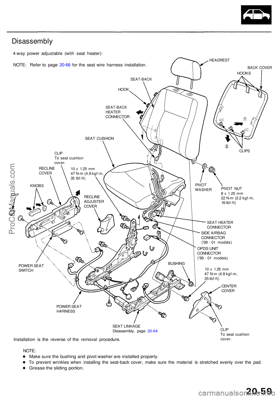
4-way powe r adjustabl e (wit h sea t heater) :
NOTE : Refe r t o pag e 20-6 6 fo r th e sea t wir e harnes s installation .
HEADREST
BACK COVE R
HOOKS
SEAT-BAC K
HOOK
POWE R SEA T
SWITC H
POWER SEA T
HARNES S
SEAT LINKAG E
Disassembly , pag e 20-6 4
Installatio n i s th e revers e o f th e remova l procedure .
CLIPTo sea t cushio n
cover .
NOTE :
Make sur e th e bushin g an d pivo t washe r ar e installe d properly .
To preven t wrinkle s whe n installin g th e seat-bac k cover , mak e sur e th e materia l i s stretche d evenl y ove r th e pad .
Greas e th e slidin g portion .
SEAT-BAC KHEATERCONNECTO R
SEA T CUSHIO N
CLIPS
PIVO T NU T8 x 1.2 5 mm22 N- m (2. 2 kgf-m ,
1 6 Ibf-ft )
SEAT HEATE RCONNECTO R
PIVO
T
WASHE R
SIDE AIRBA G
CONNECTO R
('9 9 - 0 1 models )
OPDS UNI TCONNECTO R
('9 9 - 0 1 models )
BUSHIN G
CLIPTo sea t cushio n
cover .
10 x 1.2 5 mm47 N- m (4. 8 kgf-m ,35 Ibf-ft )
RECLIN ECOVER
KNOBS
CAPRECLIN EADJUSTE R
COVE R
10 x 1.2 5 mm47 N- m (4. 8 kgf-m ,
3 5 Ibf-ft )
CENTE RCOVER
Disassembl y
ProCarManuals.com
Page 1376 of 1954
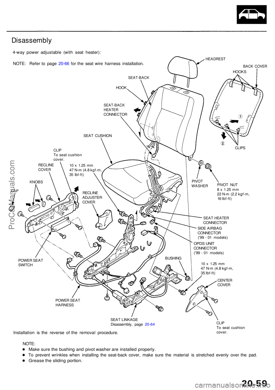
4-way powe r adjustabl e (wit h sea t heater) :
NOTE : Refe r t o pag e 20-6 6 fo r th e sea t wir e harnes s installation .
HEADREST
BACK COVE R
HOOKS
SEAT-BAC K
HOOK
POWE R SEA T
SWITC H
POWER SEA T
HARNES S
SEAT LINKAG E
Disassembly , pag e 20-6 4
Installatio n i s th e revers e o f th e remova l procedure .
CLIPTo sea t cushio n
cover .
NOTE :
Make sur e th e bushin g an d pivo t washe r ar e installe d properly .
To preven t wrinkle s whe n installin g th e seat-bac k cover , mak e sur e th e materia l i s stretche d evenl y ove r th e pad .
Greas e th e slidin g portion .
SEAT-BAC KHEATERCONNECTO R
SEA T CUSHIO N
CLIPS
PIVO T NU T8 x 1.2 5 mm22 N- m (2. 2 kgf-m ,
1 6 Ibf-ft )
SEAT HEATE RCONNECTO R
PIVO
T
WASHE R
SIDE AIRBA G
CONNECTO R
('9 9 - 0 1 models )
OPDS UNI TCONNECTO R
('9 9 - 0 1 models )
BUSHIN G
CLIPTo sea t cushio n
cover .
10 x 1.2 5 mm47 N- m (4. 8 kgf-m ,35 Ibf-ft )
RECLIN ECOVER
KNOBS
CAPRECLIN EADJUSTE R
COVE R
10 x 1.2 5 mm47 N- m (4. 8 kgf-m ,
3 5 Ibf-ft )
CENTE RCOVER
Disassembl y
ProCarManuals.com
Page 1377 of 1954
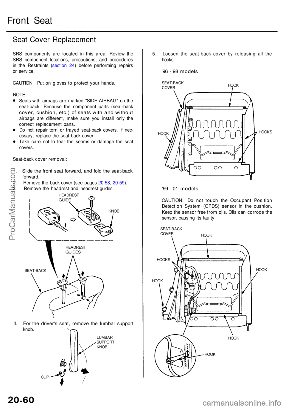
Front Sea t
SEAT-BAC K
4. Fo r th e driver' s seat , remov e th e lumba r suppor t
knob.
CLIP
5. Loose n th e seat-bac k cove r b y releasin g al l th e
hooks .
'96 - 9 8 model s
SEAT-BAC K
COVE R HOO
K
HOO K HOOK
S
'99 - 0 1 model s
CAUTION : D o no t touc h th e Occupan t Positio n
Detectio n Syste m (OPDS ) senso r i n th e cushion .
Kee p th e senso r fre e fro m oils . Oil s ca n corrod e th e
sensor , causin g it s faulty .
SEAT-BAC KCOVER
HOOK S HOO
K
HOO K HOO
K
HOO K HOO
K
LUMBA
R
SUPPOR T
KNO B
HEADRES
T
GUIDES
Seat Cove r Replacemen t
SRS component s ar e locate d i n thi s area . Revie w th e
SR S componen t locations , precautions , an d procedure s
i n th e Restraint s ( sectio n 24 ) befor e performin g repair s
o r service .
CAUTION : Pu t o n glove s t o protec t you r hands .
NOTE:
Seats wit h airbag s ar e marke d "SID E AIRBAG " o n th e
seat-back . Becaus e th e componen t part s (seat-bac k
cover, cushion , etc. ) o f seat s wit h an d withou t
airbags ar e different , mak e sur e yo u instal l onl y th e
correc t replacemen t parts .
D o no t repai r tor n o r fraye d seat-back covers. I f nec -
essary , replac e th e seat-bac k cover .
Tak e car e no t t o tea r th e seam s o r damag e th e sea t
covers .
Seat-bac k cove r removal :
1. Slid e th e fron t sea t forward , an d fol d th e seat-bac k
forward.
2 . Remov e th e bac k cove r (se e page s 20-58 , 20-59 ).
3 . Remov e th e headres t an d headres t guides .
KNOB
HEADRES TGUIDE
ProCarManuals.com
Page 1378 of 1954
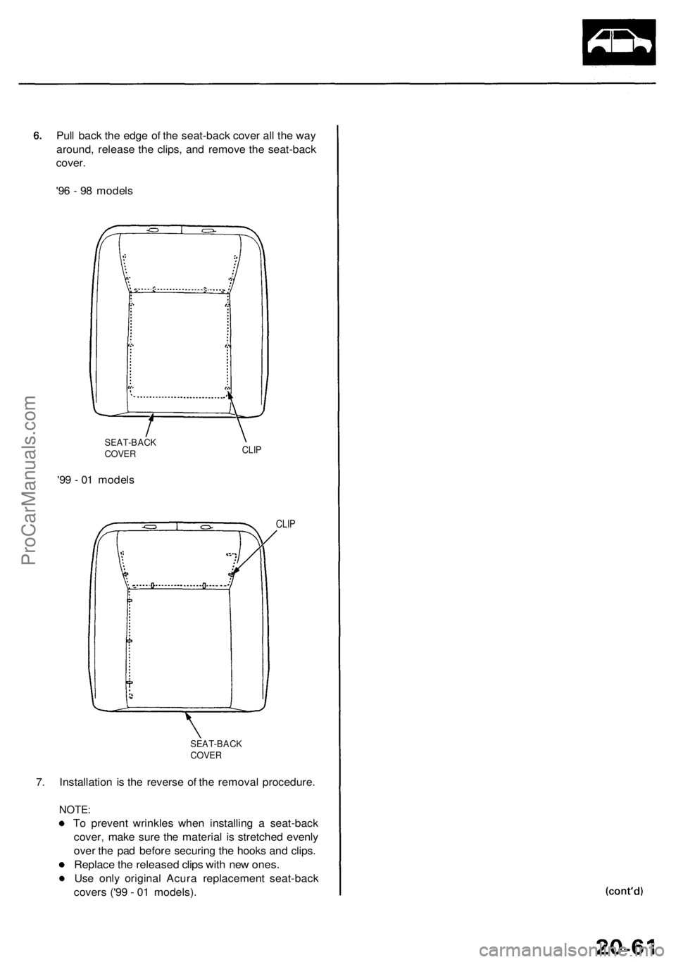
Pull bac k th e edg e o f th e seat-bac k cove r al l th e wa y
around , releas e th e clips , an d remov e th e seat-bac k
cover .
'9 6 - 9 8 model s
SEAT-BAC KCOVERCLIP
'99 - 0 1 model s
CLIP
SEAT-BAC KCOVER
7. Installatio n i s th e revers e o f th e remova l procedure .
NOTE:
To preven t wrinkle s whe n installin g a seat-bac k
cover , mak e sur e th e materia l i s stretche d evenl y
ove r th e pa d befor e securin g th e hook s an d clips .
Replac e th e release d clip s wit h ne w ones .
Use onl y origina l Acur a replacemen t seat-bac k
cover s ('9 9 - 0 1 models) .
ProCarManuals.com
Page 1379 of 1954
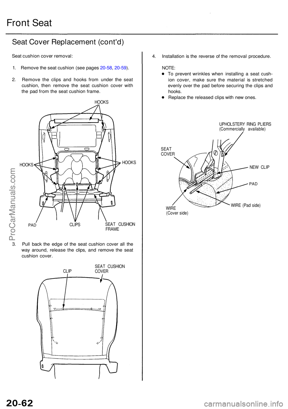
Front Sea t
Seat Cove r Replacemen t (cont'd )
Seat cushio n cove r removal :
1 . Remov e th e sea t cushio n (se e page s 20-58 , 20-59 ).
2 . Remov e th e clip s an d hook s fro m unde r th e sea t
cushion , the n remov e th e sea t cushio n cove r wit h
th e pa d fro m th e sea t cushio n frame .
HOOKS
HOOK S HOOK
S
PADCLIP S SEA
T CUSHIO N
FRAM E
3. Pul l bac k th e edg e o f th e sea t cushio n cove r al l th e
wa y around , releas e th e clips , an d remov e th e sea t
cushio n cover .
CLIP SEA
T CUSHIO NCOVER
4. Installatio n is th e revers e o f th e remova l procedure .
NOTE:
To preven t wrinkle s whe n installin g a sea t cush -
io n cover , mak e sur e th e materia l i s stretche d
evenl y ove r th e pa d befor e securin g th e clip s an d
hooks .
Replac e th e release d clip s wit h ne w ones .
SEATCOVE R
UPHOLSTER Y RIN G PLIER S
(Commerciall y available )
NE W CLI P
PAD
WIR E (Pa d side )WIRE(Cove r side )
ProCarManuals.com
Page 1380 of 1954
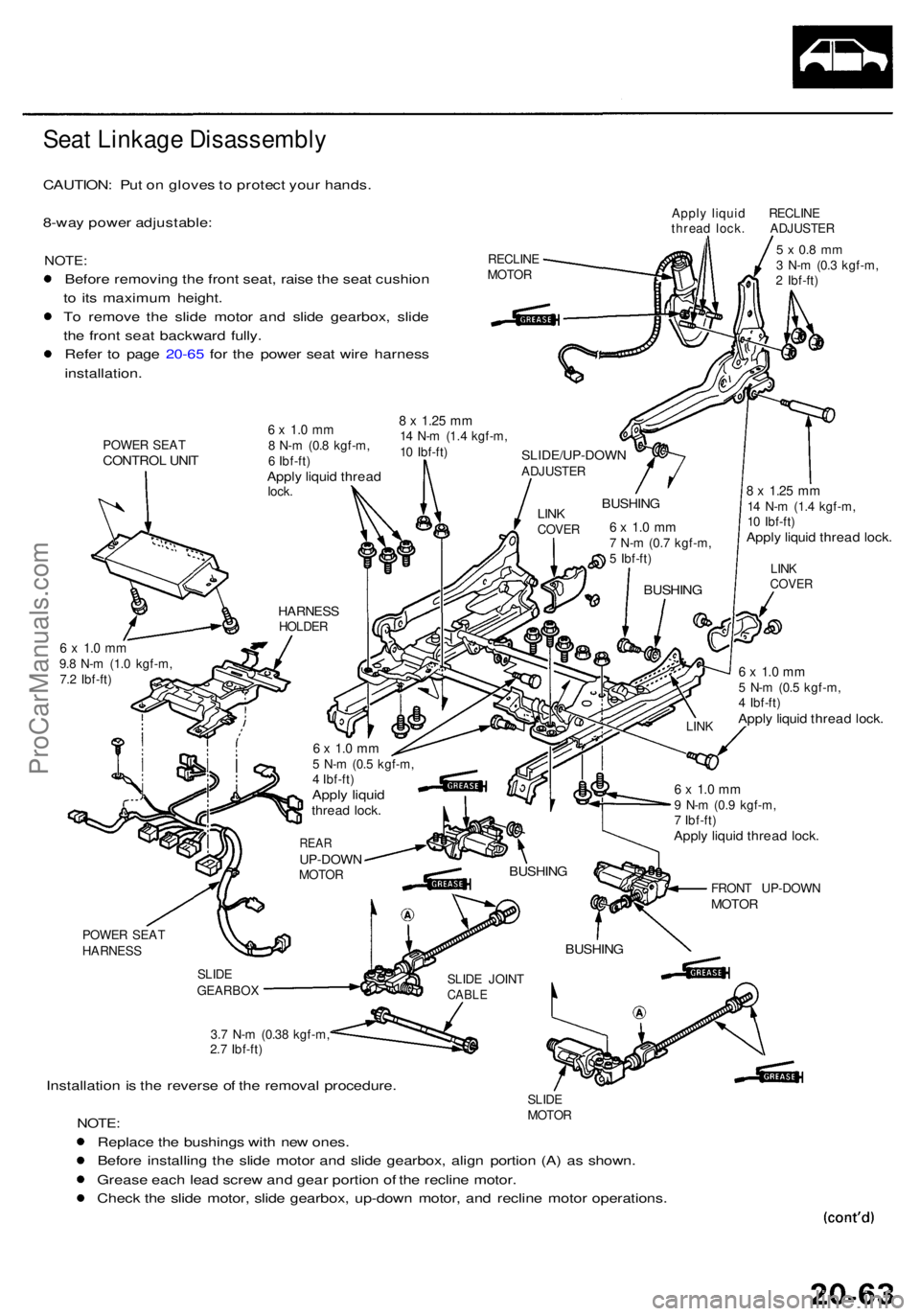
Seat Linkag e Disassembl y
CAUTION: Pu t o n glove s to protec t you r hands .
8-wa y powe r adjustable :
NOTE:
Before removin g th e fron t seat , rais e th e sea t cushio n
t o it s maximu m height .
T o remov e th e slid e moto r an d slid e gearbox , slid e
th e fron t sea t backwar d fully .
Refe r t o pag e 20-6 5 fo r th e powe r sea t wir e harnes s
installation .
POWER SEA TCONTRO L UNI T
Appl y liqui d RECLIN E
threa d lock . ADJUSTE R
RECLIN E
MOTO R
5 x 0. 8 m m3 N- m (0. 3 kgf-m ,
2 Ibf-ft )
8 x 1.2 5 mm14 N- m (1. 4 kgf-m ,
1 0 Ibf-ft )
Apply liqui d threa d lock .
6 x 1. 0 m m9.8 N- m (1. 0 kgf-m ,
7. 2 Ibf-ft )6 x 1. 0 m m5 N- m (0. 5 kgf-m ,
4 Ibf-ft )
Apply liqui d threa d lock .
POWE R SEA T
HARNES S
SLIDE
GEARBO X
3.7 N- m (0.3 8 kgf-m ,
2. 7 Ibf-ft )
Installatio n is th e revers e o f th e remova l procedure .SLIDE
MOTO R
NOTE:
Replac e th e bushing s wit h ne w ones .
Befor e installin g th e slid e moto r an d slid e gearbox , alig n portio n (A) a s shown .
Greas e eac h lea d scre w an d gea r portio n o f th e reclin e motor .
Chec k th e slid e motor , slid e gearbox , up-dow n motor , an d reclin e moto r operations .
SLIDE JOIN TCABLE
BUSHIN G
FRONT UP-DOW NMOTOR
6 x 1. 0 m m9 N- m (0. 9 kgf-m ,
7 Ibf-ft )
Apply liqui d threa d lock .
BUSHIN G
LINK LIN
K
COVE RBUSHIN G
6 x 1. 0 m m7 N- m (0. 7 kgf-m ,
5 Ibf-ft )
BUSHIN GLINKCOVE R
SLIDE/UP-DOW NADJUSTER
6 x 1. 0 m m8 N- m (0. 8 kgf-m ,
6 Ibf-ft )
Apply liqui d threa dlock.
8 x 1.2 5 m m14 N- m (1. 4 kgf-m ,
1 0 Ibf-ft )
HARNES SHOLDER
6 x 1. 0 m m5 N- m (0. 5 kgf-m ,
4 Ibf-ft )
Apply liqui dthrea d lock .
REARUP-DOW NMOTOR
ProCarManuals.com