ACURA RL KA9 1996 Service Repair Manual
Manufacturer: ACURA, Model Year: 1996, Model line: RL KA9, Model: ACURA RL KA9 1996Pages: 1954, PDF Size: 61.44 MB
Page 321 of 1954
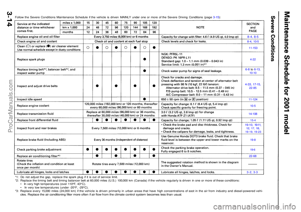
Follow th e Sever e Condition s Maintenanc e Schedul e i f th e vehicl e i s drive n MAINL Y unde r on e o r mor e o f th e Sever e Drivin g Condition s (pag e 3-15 ):
8-4, 8-5
8-4, 10- 5
11-153
4-22
6-8 to 6-13 ,
10-1 0
4-33 , 17-15 ,22-85
11-124
10-5
14-10 8
15-4
19-10 , 19-11 ,12, 17 , 18 ,19-19, 19-2 3
19-8
19-6
22-6 8
3-2, 3-3
*1: D o no t adjus t th e gap , replac e th e spar k plu g i f i t i s ou t o f servic e limit .
*2 : Replac e th e timin g bel t an d timin g balance r bel t a t 60,00 0 mile s (U.S. ) 100,00 0 k m (Canada ) i f th e vehicl e regularl y is drive n in on e o r mor e o f thes e conditions :
• I n ver y hig h temperature s (ove r 110°F , 43°C) .
• I n ver y lo w temperature s (unde r -20°F , -29°C) .
*3 : Replac e ever y 15,00 0 mile s (24,00 0 km ) i f th e vehicl e i s drive n primaril y i n urba n area s tha t hav e hig h concentration s o f soo t i n th e ai r fro m industr y an d diesel-powere d vehi -
cles. Replac e th e ai r conditionin g filte r mor e ofte n if ai r flo w fro m th e climat e contro l syste m become s les s tha n usual .
ProCarManuals.com
Page 322 of 1954
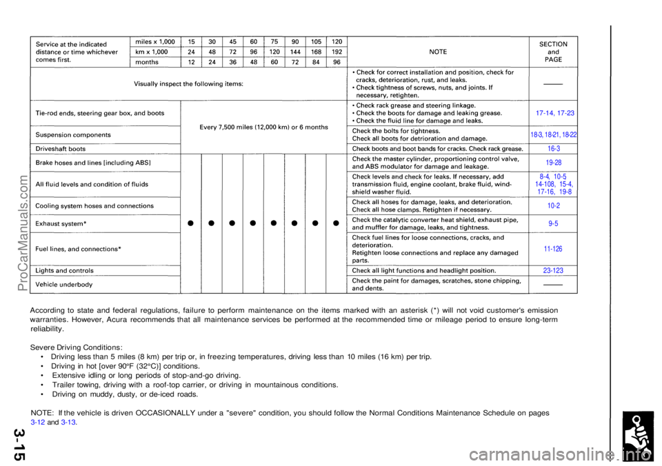
According t o stat e an d federa l regulations , failur e t o perfor m maintenanc e o n th e item s marke d wit h a n asteris k (* ) wil l no t voi d customer' s emissio n
warranties . However , Acur a recommend s tha t al l maintenanc e service s b e performe d a t th e recommende d tim e o r mileag e perio d t o ensur e long-ter m
reliability.
Severe Drivin g Conditions :
• Drivin g les s tha n 5 mile s ( 8 km ) pe r tri p or , i n freezin g temperatures , drivin g les s tha n 1 0 mile s (1 6 km ) pe r trip .
• Drivin g in ho t [ove r 90° F (32°C) ] conditions .
• Extensiv e idlin g o r lon g period s o f stop-and-g o driving .
• Traile r towing , drivin g wit h a roof-to p carrier , o r drivin g i n mountainou s conditions .
• Drivin g o n muddy , dusty , o r de-ice d roads .
NOTE : I f th e vehicl e is drive n OCCASIONALL Y unde r a "severe " condition , yo u shoul d follo w th e Norma l Condition s Maintenanc e Schedul e o n page s
3-1 2 an d 3-13 .
17-14, 17-23
18-3, 18-21, 18-22
16-3
19-28
8-4, 10-5,14-108, 15-4,17-16, 19-8
10-2
9-5
11-126
23-123
ProCarManuals.com
Page 323 of 1954
Special Tool s
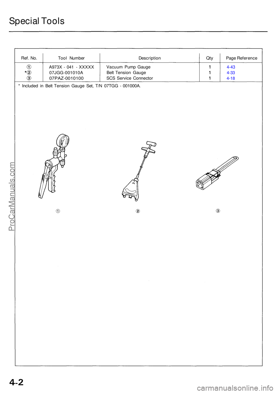
Ref. No.Too l Numbe r DescriptionQtyPag e Referenc e
A973 X - 04 1 - XXXX X
07JGG-001010 A
07PAZ-0010100
Vacuum Pum p Gaug e
Bel t Tensio n Gaug e
SC S Servic e Connecto r4-43
4-33
4-1 8
* Include d i n Bel t Tensio n Gaug e Set , T/ N 07TG G - 001000A .
ProCarManuals.com
Page 324 of 1954
Starting Syste m
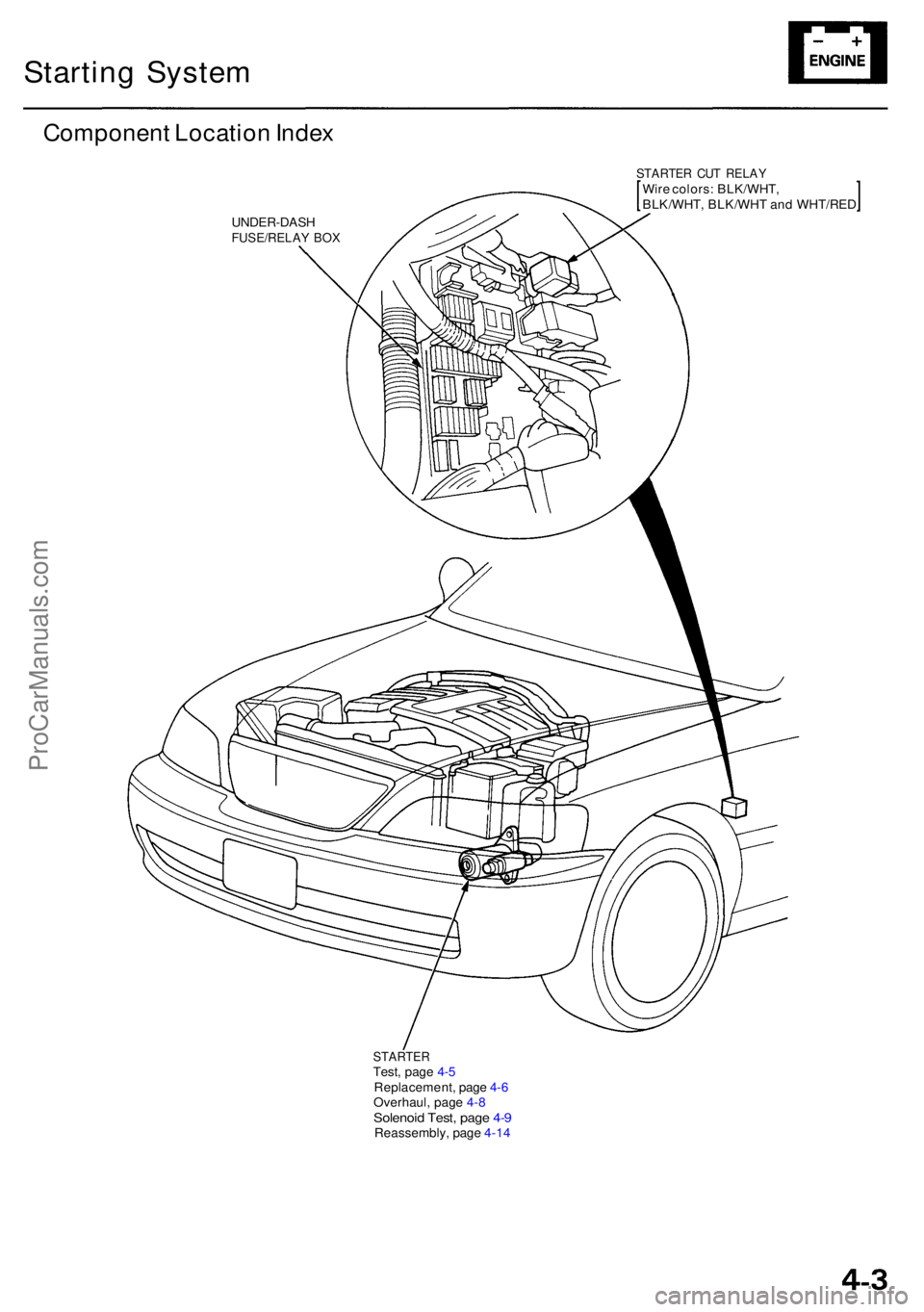
Componen t Locatio n Inde x
STARTE R CU T RELA YWire colors : BLK/WHT ,
BLK/WHT , BLK/WH T an d WHT/RE D
UNDER-DAS HFUSE/RELAY BO X
STARTE RTest, pag e 4- 5
Replacement , pag e 4- 6
Overhaul , pag e 4- 8
Solenoi d Test , pag e 4- 9Reassembly , pag e 4-1 4
ProCarManuals.com
Page 325 of 1954
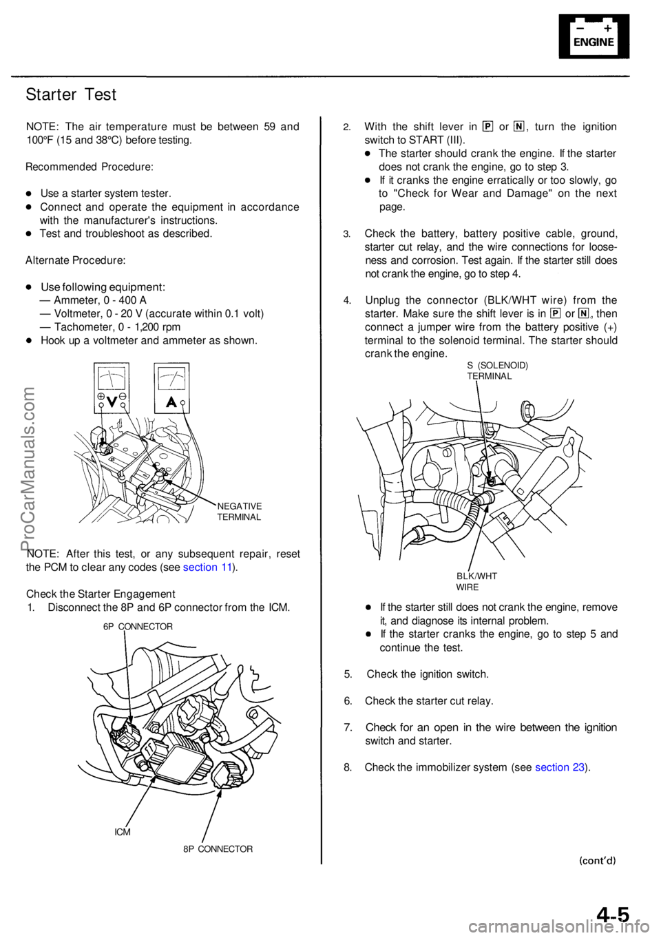
Starter Tes t
NOTE : Th e ai r temperatur e mus t b e betwee n 5 9 an d
100° F (1 5 an d 38°C ) befor e testing .
Recommende d Procedure :
Use a starte r syste m tester .
Connec t an d operat e th e equipmen t i n accordanc e
wit h th e manufacturer' s instructions .
Tes t an d troubleshoo t a s described .
Alternat e Procedure :
Use followin g equipment :
— Ammeter , 0 - 40 0 A
— Voltmeter , 0 - 2 0 V (accurat e withi n 0. 1 volt )
— Tachometer , 0 - 1,20 0 rp m
Hoo k u p a voltmete r an d ammete r a s shown .
NEGATIV E
TERMINA L
NOTE: Afte r thi s test , o r an y subsequen t repair , rese t
th e PC M to clea r an y code s (se e sectio n 11 ).
Chec k th e Starte r Engagemen t
1 . Disconnec t th e 8 P an d 6 P connecto r fro m th e ICM .
6P CONNECTO R
ICM
8P CONNECTO R
2.
3.
Wit h th e shif t leve r i n o r , turn th e ignitio n
switc h to STAR T (III) .
Th e starte r shoul d cran k th e engine . I f th e starte r
doe s no t cran k th e engine , g o t o ste p 3 .
I f i t crank s th e engin e erraticall y o r to o slowly , g o
t o "Chec k fo r Wea r an d Damage " o n th e nex t
page .
Chec k th e battery , batter y positiv e cable , ground ,
starte r cu t relay , an d th e wir e connection s fo r loose -
nes s an d corrosion . Tes t again . I f th e starte r stil l doe s
no t cran k th e engine , g o to ste p 4 .
Unplu g th e connecto r (BLK/WH T wire ) fro m th e
starter . Mak e sur e th e shif t leve r i s i n o r , then
connec t a jumpe r wir e fro m th e batter y positiv e (+ )
termina l t o th e solenoi d terminal . Th e starte r shoul d
cran k th e engine .
S (SOLENOID )
TERMINA L
BLK/WH T
WIRE
If th e starte r stil l doe s no t cran k th e engine , remov e
it , an d diagnos e it s interna l problem .
I f th e starte r crank s th e engine , g o t o ste p 5 an d
continu e th e test .
5 . Chec k th e ignitio n switch .
6 . Chec k th e starte r cu t relay .
7. Chec k fo r a n ope n i n th e wir e betwee n th e ignitio n
switch an d starter .
8 . Chec k th e immobilize r syste m (se e sectio n 23 ).
4 .
ProCarManuals.com
Page 326 of 1954
Starting Syste m
Starte r Tes t (cont'd )
Check fo r Wea r an d Damag e
Th e starte r shoul d cran k th e engin e smoothl y an d steadily .
I f th e starte r engages , bu t crank s th e engin e erratically ,
remov e it , an d inspec t th e starte r driv e gea r an d driv e
plat e rin g gea r fo r damage .
Chec k th e driv e gea r overrunning clutch fo r bindin g o r
slippin g whe n th e armatur e is rotate d wit h th e driv e gea r
held . I f th e clutc h i s damaged , replac e th e clutc h assem -
bly.
Chec k Crankin g Voltag e an d Curren t Dra w
Crankin g voltag e shoul d b e n o les s tha n 8. 0 volts .
Curren t draw shoul d b e n o mor e tha n 40 0 amperes .
I f crankin g voltag e i s to o low , o r curren t draw too high ,
chec k for :
Dea d o r lo w batter y
Ope n circui t i n starte r armatur e commutato r segment s
Starte r armatur e draggin g
Shorte d armatur e windin g
Excessiv e dra g in engin e
Chec k Crankin g rp m
Engin e spee d durin g crankin g shoul d b e abov e 10 0 rpm .
I f spee d is to o low , chec k for :
Loos e batter y o r starte r terminal s
Excessivel y wor n starte r brushe s
Ope n circui t i n commutato r segment s
Dirt y o r damage d helica l splin e o r driv e gea r
Defectiv e driv e gea r overrunnin g clutc h
Chec k Starte r Disengagemen t
With th e shif t leve r i n tur n th e ignitio n switc h t o
"STAR T (III)" , an d releas e t o "O N (II)" . Th e starte r driv e
gea r shoul d disengag e fro m th e driv e plat e rin g gea r
whe n yo u releas e th e key .
I f th e driv e gea r hang s u p o n th e driv e plat e rin g gear ,
check for :
• Solenoi d plunge r an d switc h malfunctio n
• Dirt y driv e gea r assembl y o r damage d overrunnin g
clutc h
ProCarManuals.com
Page 327 of 1954
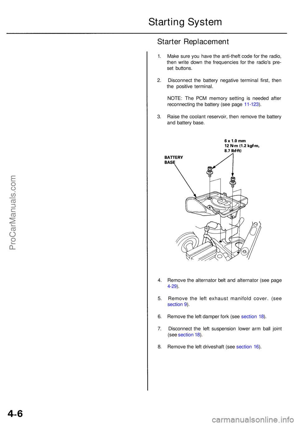
4. Remov e th e alternato r bel t an d alternato r (se e pag e
4-29).
5 . Remov e th e lef t exhaus t manifol d cover . (se e
sectio n 9 ).
6 . Remov e th e lef t dampe r for k (se e sectio n 18 ).
7 . Disconnec t th e lef t suspensio n lowe r ar m bal l join t
(se e sectio n 18 ).
8 . Remov e th e lef t driveshaf t (se e sectio n 16 ).
Starte r Replacemen t
1. Mak e sur e yo u hav e th e anti-thef t cod e fo r th e radio ,
the n writ e dow n th e frequencie s fo r th e radio' s pre -
se t buttons .
2 . Disconnec t th e batter y negativ e termina l first , the n
th e positiv e terminal .
NOTE : Th e PC M memor y settin g i s neede d afte r
reconnectin g th e batter y (se e pag e 11-123 ).
3 . Rais e th e coolan t reservoir , the n remov e th e batter y
an d batter y base .
Startin g Syste m
ProCarManuals.com
Page 328 of 1954
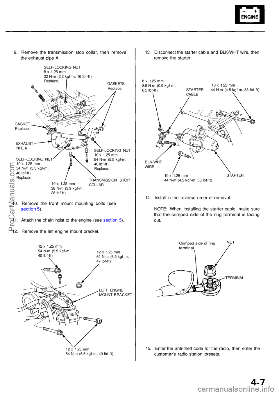
GASKETReplace .
EXHAUS T
PIP E A
SELF-LOCKIN G NU T10 x 1.2 5 mm54 N- m (5. 5 kgf-m ,
4 0 Ibf-ft )
Replace .
10 x 1.2 5 mm38 N- m (3. 9 kgf-m ,
2 8 Ibf-ft ) SELF-LOCKIN
G NU T
10 x 1.2 5 mm54 N- m (5. 5 kgf-m ,
4 0 Ibf-ft )
Replace .
TRANSMISSIO N STO PCOLLA R
10. Remov e th e fron t moun t mountin g bolt s (se e
sectio n 5 ).
11 . Attach the chai n hois t t o th e engine (see sectio n 5 ).
12 . Remov e th e lef t engin e moun t bracket .
12 x 1.2 5 mm54 N- m (5. 5 kgf-m ,
4 0 Ibf-ft )12 x 1.2 5 mm64 N- m (6. 5 kgf-m ,
4 7 Ibf-ft )
LEF T ENGIN E
MOUN T BRACKE T
12 x 1.2 5 mm54 N- m (5. 5 kgf-m , 4 0 Ibf-ft )
13. Disconnec t th e starte r cabl e an d BLK/WH T wire , the n
remov e th e starter .
8 x 1.2 5 mm8.8 N- m (0. 9 kgf-m ,
6. 5 Ibf-ft )10 x 1.2 5 mmSTARTE R 4 4 N- m (4. 5 kgf-m , 3 3 Ibf-ft )CABL E
BLK/WH TWIRE
10 x 1.2 5 mm44 N- m (4. 5 kgf-m , 3 3 Ibf-ft )STARTE R
14. Instal l i n th e revers e orde r o f removal .
NOTE : Whe n installin g th e starte r cable , mak e sur e
that th e crimpe d sid e o f th e rin g termina l i s facin g
out.
Crimpe d sid e o f rin gtermina l
NUT
TERMINA L
15. Ente r th e anti-theft code fo r th e radio , the n ente r th e
customer' s radi o statio n presets .
9
. Remov e th e transmissio n sto p collar , the n remov e
th e exhaus t pip e A .
GASKET SReplace.
SELF-LOCKIN G NU T8 x 1.2 5 mm22 N- m (2. 2 kgf-m , 1 6 Ibf-ft )Replace .
ProCarManuals.com
Page 329 of 1954
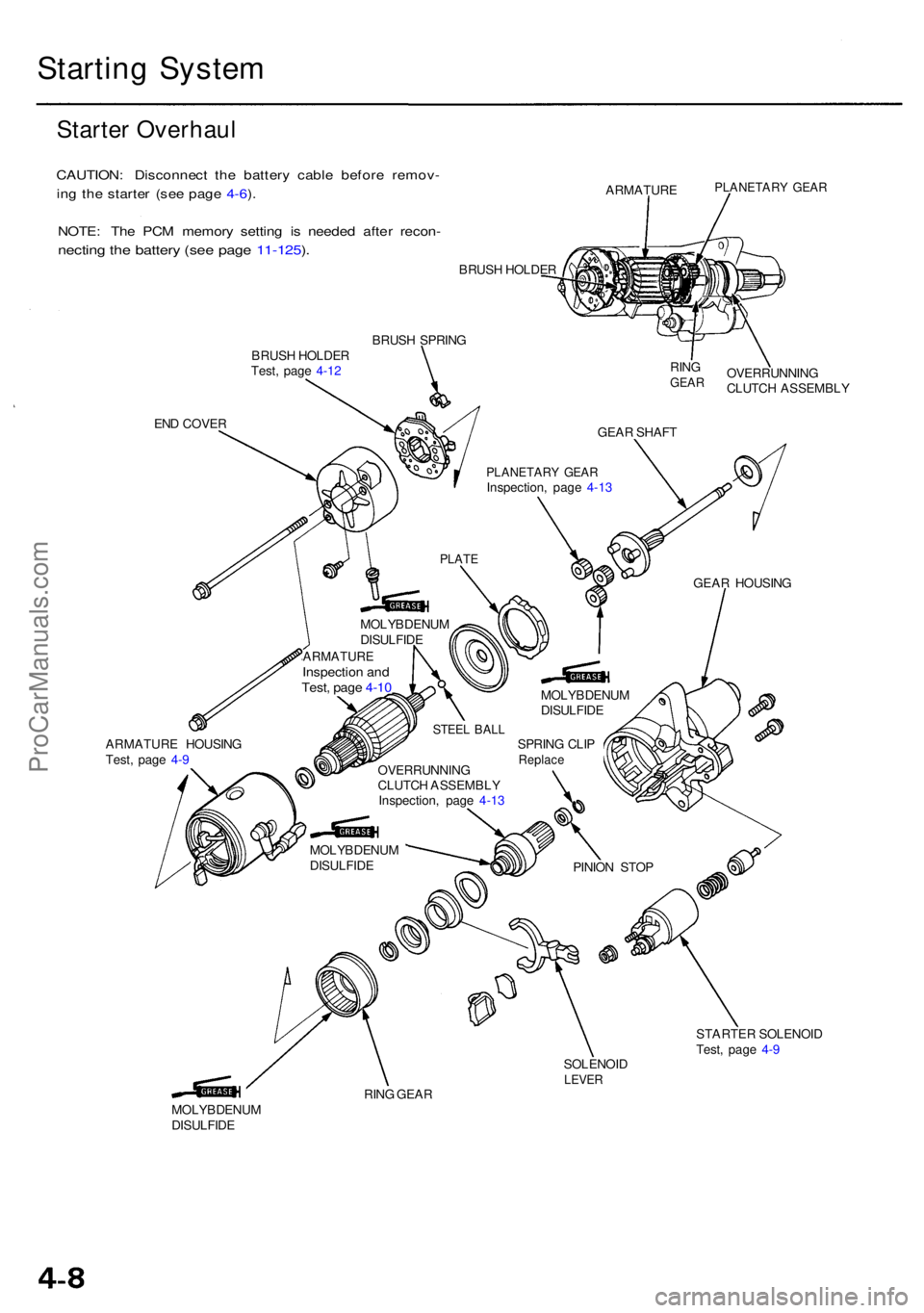
Starting Syste m
Starter Overhau l
CAUTION : Disconnec t th e batter y cabl e befor e remov -
in g th e starte r (se e pag e 4-6 ).
NOTE : Th e PC M memor y settin g i s neede d afte r recon -
necting th e batter y (se e pag e 11-125 ).
BRUS H HOLDE R
BRUS H SPRIN G
BRUS H HOLDE R
Test , pag e 4-1 2
EN D COVE R RIN
G
GEA R
ARMATUR E HOUSIN G
Test , pag e 4- 9
MOLYBDENU M
DISULFID E OVERRUNNIN
G
CLUTC H ASSEMBL Y
GEA R SHAF T
PLANETAR Y GEA RInspection , pag e 4-1 3
PLAT E
MOLYBDENU M
DISULFID E
ARMATUR EInspection an dTest , pag e 4-1 0
MOLYBDENU M
DISULFID EOVERRUNNIN
G
CLUTC H ASSEMBL Y
Inspection , pag e 4-1 3
SOLENOID
LEVER
STARTE R SOLENOI D
Test , pag e 4- 9
RIN G GEA R PINIO
N STO P
SPRIN
G CLI P
Replac e
MOLYBDENU M
DISULFID E GEA
R HOUSIN G
PLANETAR Y GEA RARMATUR E
STEEL BAL L
ProCarManuals.com
Page 330 of 1954
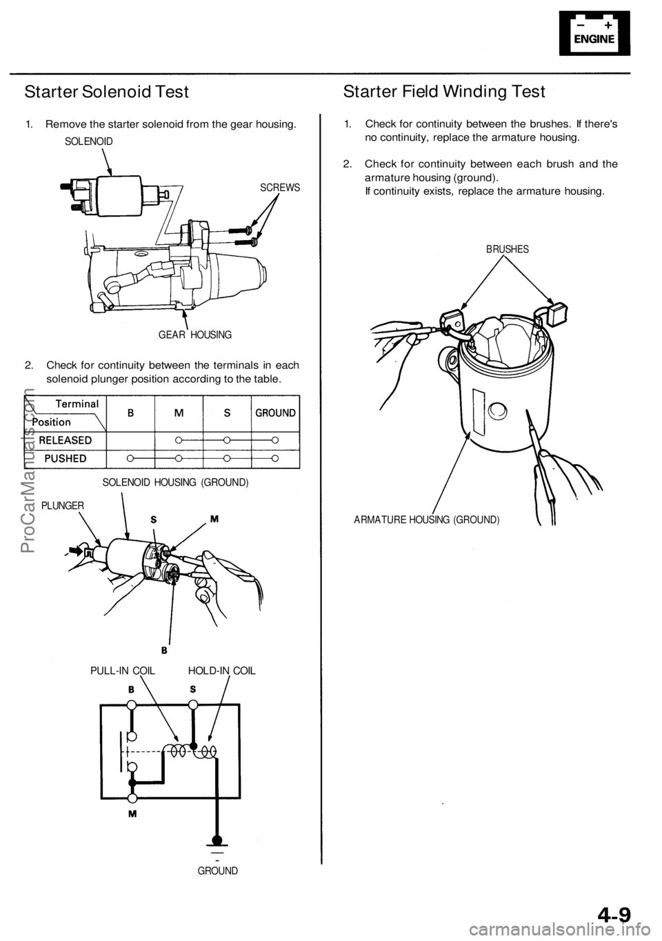
Starter Solenoid Test
1. Remove the starter solenoid from the gear housing.
SOLENOID
SCREWS
GEAR HOUSING
2. Check for continuity between the terminals in each
solenoid plunger position according to the table.
PLUNGER
SOLENOID HOUSING (GROUND)
Starter Field Winding Test
1. Check for continuity between the brushes. If there's
no continuity, replace the armature housing.
2. Check for continuity between each brush and the
armature housing (ground).
If continuity exists, replace the armature housing.
BRUSHES
ARMATURE HOUSING (GROUND)
GROUND
PULL-IN COIL
HOLD-IN COILProCarManuals.com