ACURA RL KA9 1996 Service Repair Manual
Manufacturer: ACURA, Model Year: 1996, Model line: RL KA9, Model: ACURA RL KA9 1996Pages: 1954, PDF Size: 61.44 MB
Page 351 of 1954
Charging System
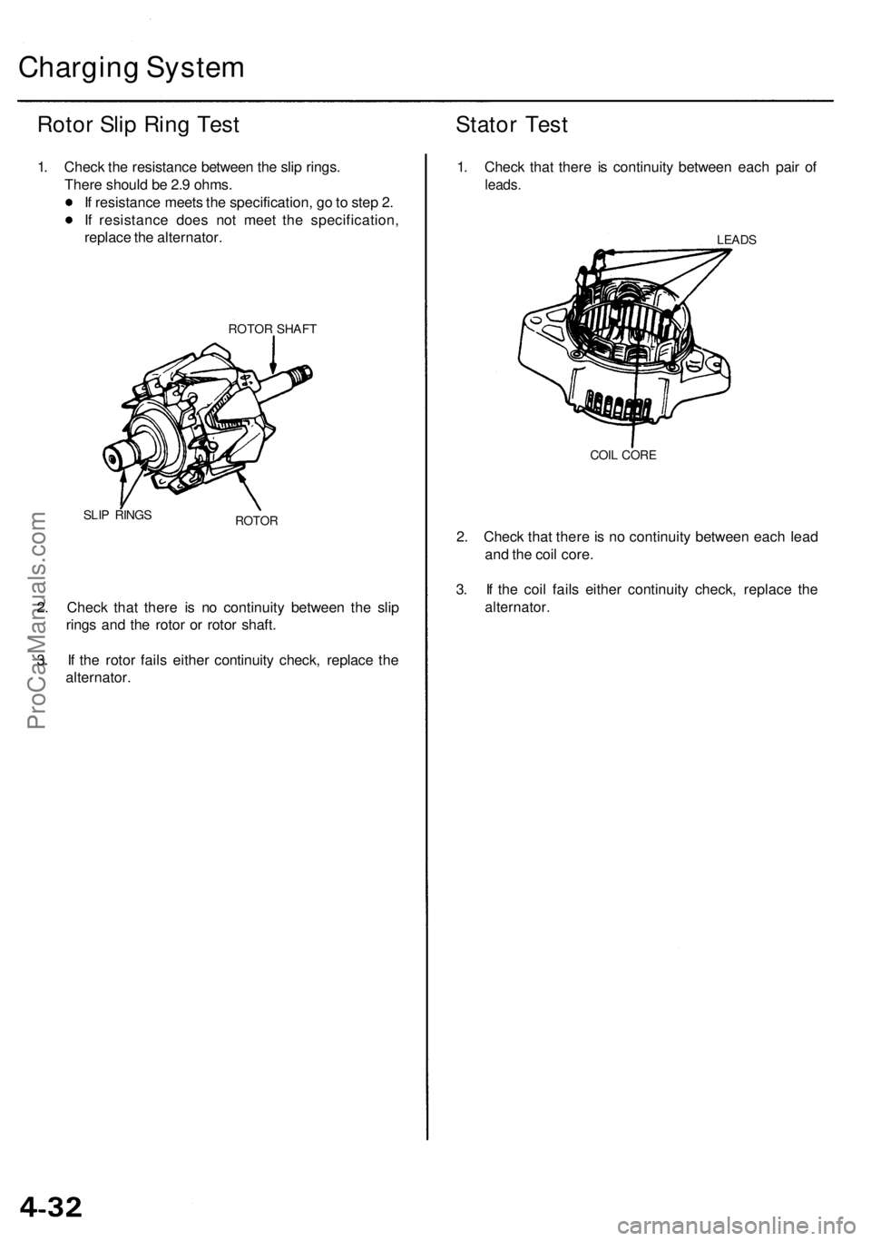
Rotor Slip Ring Test
1. Check the resistance between the slip rings.
There should be 2.9 ohms.
If resistance meets the specification, go to step 2.
If resistance does not meet the specification,
replace the alternator.
ROTOR SHAFT
SLIP RINGS
ROTOR
2. Check that there is no continuity between the slip
rings and the rotor or rotor shaft.
3. If the rotor fails either continuity check, replace the
alternator.
Stator Test
1. Check that there is continuity between each pair of
leads.
LEADS
COIL CORE
2. Check that there is no continuity between each lead
and the coil core.
3. If the coil fails either continuity check, replace the
alternator.ProCarManuals.com
Page 352 of 1954
Alternator Bel t Inspectio n an d Adjustmen t
NOTE: Whe n usin g a ne w belt , firs t adjus t th e deflectio n
o r tensio n t o th e value s fo r th e ne w belt , the n readjus t
th e deflectio n o r tensio n t o th e value s fo r th e use d bel t
afte r runnin g engin e fo r 5 minutes .
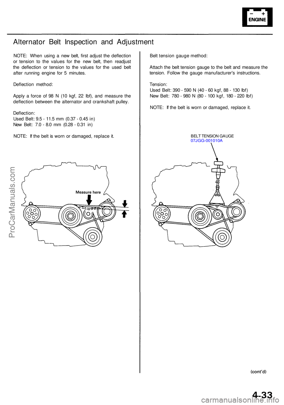
Deflectio n method :
Appl y a forc e o f 9 8 N (1 0 kgf , 2 2 Ibf) , an d measur e th e
deflectio n betwee n th e alternato r an d crankshaf t pulley .
Deflection :
Use d Belt : 9. 5 - 11. 5 m m (0.3 7 - 0.4 5 in )
Ne w Belt : 7. 0 - 8. 0 m m (0.2 8 - 0.3 1 in )
NOTE : I f th e bel t i s wor n o r damaged , replac e it . Bel
t tensio n gaug e method :
Attac h th e bel t tensio n gaug e t o th e bel t an d measur e th e
tension . Follo w th e gaug e manufacturer' s instructions .
Tension :
Use d Belt : 39 0 - 59 0 N (4 0 - 6 0 kgf , 8 8 - 13 0 Ibf )
Ne w Belt : 78 0 - 98 0 N (8 0 - 10 0 kgf , 18 0 - 22 0 Ibf )
NOTE : I f th e bel t i s wor n o r damaged , replac e it .
BEL T TENSIO N GAUG E07JGG-001010 A
ProCarManuals.com
Page 353 of 1954
Charging Syste m
Alternato r Bel t Inspectio n an d
Adjustmen t (cont'd )
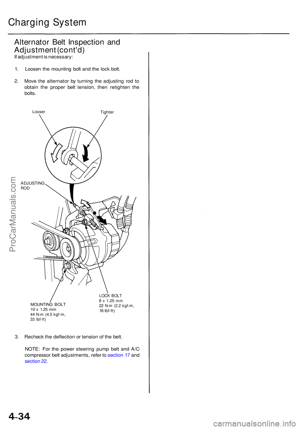
If adjustmen t i s necessary :
1 . Loose n th e mountin g bol t an d th e loc k bolt .
2 . Mov e th e alternato r b y turnin g th e adjustin g ro d t o
obtai n th e prope r bel t tension , the n retighte n th e
bolts .
Loose rTighte r
ADJUSTIN G
ROD
MOUNTIN G BOL T10 x 1.2 5 mm44 N- m (4. 5 kgf-m ,33 Ibf-ft )
LOCK BOL T8 x 1.2 5 mm22 N- m (2. 2 kgf-m ,16 Ibf-ft )
3. Rechec k th e deflectio n o r tensio n o f th e belt .
NOTE : Fo r th e powe r steerin g pum p bel t an d A/ C
compresso r bel t adjustments , refe r t o sectio n 1 7 an d
sectio n 22 .
ProCarManuals.com
Page 354 of 1954
Cruise Contro l
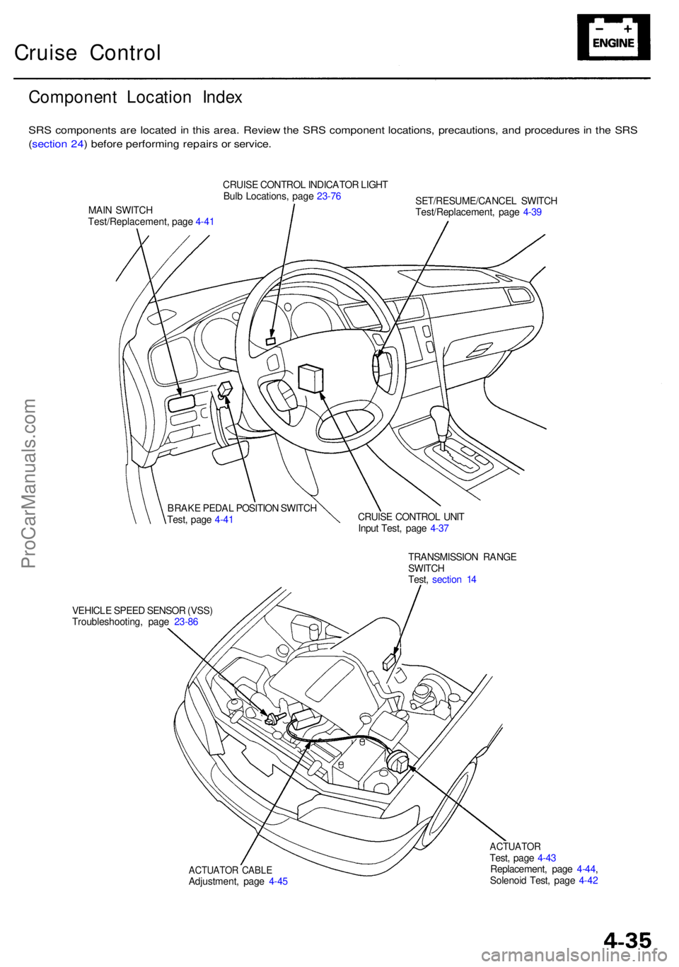
Componen t Locatio n Inde x
SRS component s ar e locate d i n thi s area . Revie w th e SR S componen t locations , precautions , an d procedure s i n th e SR S
( sectio n 24 ) befor e performin g repair s o r service .
CRUISE CONTRO L INDICATO R LIGH T
Bul b Locations , pag e 23-7 6
MAI N SWITC H
Test/Replacement , pag e 4-4 1 SET/RESUME/CANCE
L SWITC H
Test/Replacement , pag e 4-3 9
CRUIS E CONTRO L UNI T
Inpu t Test , pag e 4-3 7
VEHICL E SPEE D SENSO R (VSS )
Troubleshooting , pag e 23-86 TRANSMISSIO
N RANG E
SWITC H
Test , sectio n 1 4
ACTUATO R CABL EAdjustment , pag e 4-4 5
ACTUATO RTest, pag e 4-4 3
Replacement , pag e 4-44 ,
Solenoi d Test , pag e 4-4 2
BRAK
E PEDA L POSITIO N SWITC H
Test , pag e 4-4 1
ProCarManuals.com
Page 355 of 1954
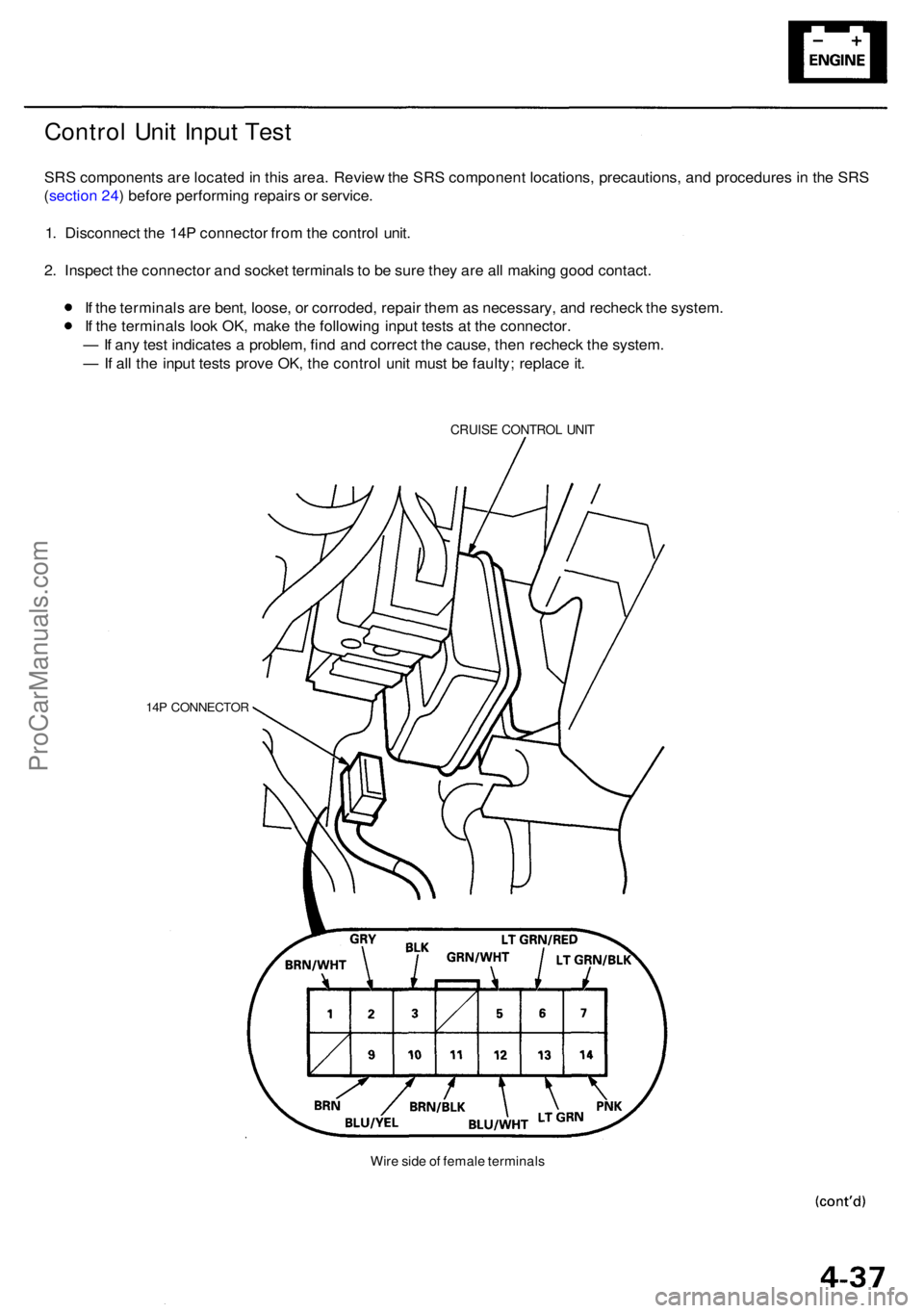
Control Uni t Inpu t Tes t
SRS component s ar e locate d in thi s area . Revie w th e SR S componen t locations , precautions , an d procedure s i n th e SR S
( sectio n 24 ) befor e performin g repair s o r service .
1 . Disconnec t th e 14 P connecto r fro m th e contro l unit .
2 . Inspec t th e connecto r an d socke t terminal s t o b e sur e the y ar e al l makin g goo d contact .
I f th e terminal s ar e bent , loose , o r corroded , repai r the m as necessary , an d rechec k th e system .
I f th e terminal s loo k OK , mak e th e followin g inpu t test s a t th e connector .
— If an y tes t indicate s a problem , fin d an d correc t th e cause , the n rechec k th e system .
— If al l th e inpu t test s prov e OK , th e contro l uni t mus t b e faulty ; replac e it .
CRUIS E CONTRO L UNI T
14P CONNECTO R
Wire sid e o f femal e terminal s
ProCarManuals.com
Page 356 of 1954

Cruise Control
Control Unit Input Test (cont'd)
Cavity Wire
Test condition
Test: Desired result
Possible cause if result is not obtained
3
13
7
6
14
12
2
5
10
9
11
1
BLK
LT GRN
LT GRN/BLK
LT GRN/RED
PNK
BLU/WHT
GRY
GRN/WHT
BLU/YEL
BRN
BRN/BLK
BRN/WHT
Under all conditions
Ignition switch ON (II) and
main switch ON
Resume button pushed
Cancel button pushed
Set button pushed
Cancel button pushed
Shift lever in , or
Ignition switch ON (II), and
main switch ON; raise the
front of the vehicle, and rotate
one wheel slowly while
holding the other wheel.
Ignition switch ON (II), main
switch ON; brake pedal
pressed, then released
Brake pedal pressed then
released
Ignition switch ON (II)
Under all conditions
Under all conditions
Under all conditions
Check for continuity to ground:
There should be continuity.
Check for voltage to ground:
There should be battery voltage.
Check for voltage to ground:
There should be battery voltage.
When testing terminal No. 7, there
should be no voltage on terminal No. 6.
Check for voltage to ground:
There should be battery voltage.
When testing terminal No. 7, there
should be voltage on terminal No. 6.
Check for voltage to ground:
There should be battery voltage.
When testing terminal No. 6, there
should be no voltage on terminal No. 7.
Check for voltage to ground:
There should be battery voltage.
When testing terminal No. 6, there
should be voltage on terminal No. 7.
Check for continuity to ground:
There should be continuity.
NOTE: There should be no continuity
when the shift lever is in other positions.
Check for voltage between the
BLU/ WHT and BLK terminals:
There should be cycle 0 - 5 V or
battery voltage.
Check for voltage to ground:
There should be 0 V with the pedal
pressed, and battery voltage with
the pedal released.
Check for voltage to ground:
There should be battery voltage with
the pedal pressed, and 0 V with the
pedal released.
Attach to ground:
The cruise light in the gauge assembly
should come on.
Check for resistance to ground:
There should be 80 -120
Check for resistance to ground:
There should be 70 -110
Check for resistance to ground:
There should be 40 - 60
• Poor ground (G401, G402)
• An open in the wire
• Blown No. 20 (20 A) fuse in the
under-dash fuse/relay box
• Faulty main switch
• An open in the wire
• Blown No. 39 (15 A) fuse in the
under-hood fuse/relay box
• Faulty horn relay
• Faulty set/resume/cancel switch
• Faulty cable reel
• An open in the wire
• Short between LT GRN/BLK and
LT GRN/RED wires
• Blown No. 39 (15 A) fuse in the
under-hood fuse/relay box
• Faulty horn relay
• Faulty set/resume/cancel switch
• Faulty cable reel
• An open in the wire
• Blown No. 39 (15 A) fuse in the
under-hood fuse/relay box
• Faulty horn relay
• Faulty set/resume/cancel switch
• Faulty cable reel
• An open in the wire
• Short between LT GRN/BLK and
LT GRN/RED wires
• Blown No. 39 (15 A) fuse in the
under-hood fuse/relay box
• Faulty horn relay
• Faulty set/resume/cancel switch
• Faulty cable reel
• An open in the wire
• Faulty A/T gear position switch
• Poor ground (G401, G402)
• An open in the wire
• Faulty vehicle speed sensor (VSS)
• An open in the wire
• Short to ground
• Blown No. 39 (15 A) fuse in the
under-hood fuse/relay box
• Faulty brake switch
• An open in the wire
• Blown No. 39 (15 A) fuse in the
under-hood fuse/relay box
• Faulty brake switch
• An open in the wire
• Blown bulb
• Faulty gauge circuit
• An open in the wire
• Faulty actuator solenoid
• An open in the wireProCarManuals.com
Page 357 of 1954
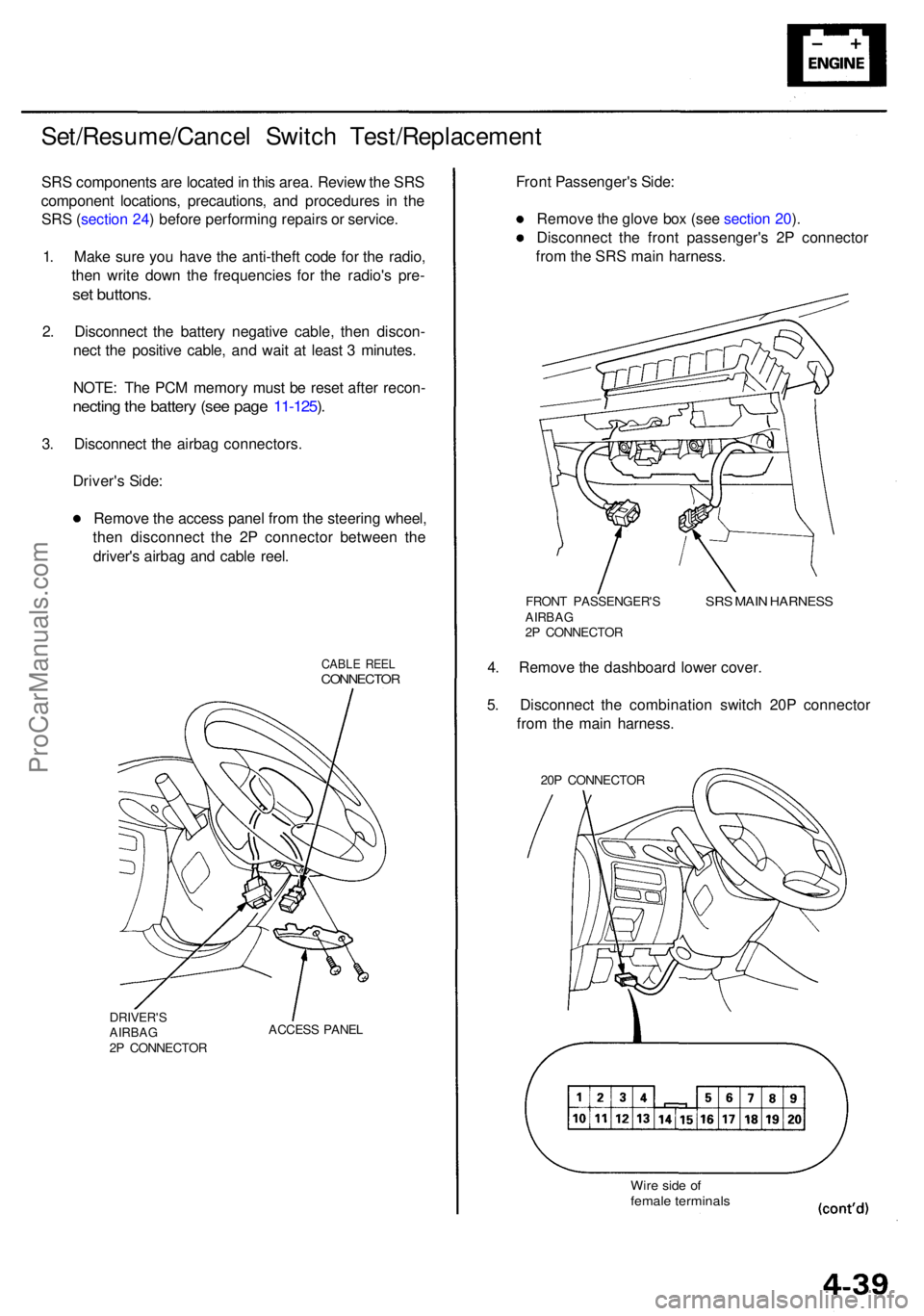
Set/Resume/Cancel Switc h Test/Replacemen t
SRS component s ar e locate d in thi s area . Revie w th e SR S
componen t locations , precautions , an d procedure s i n th e
SR S (sectio n 24 ) befor e performin g repair s o r service .
1 . Mak e sur e yo u hav e th e anti-thef t cod e fo r th e radio ,
the n writ e dow n th e frequencie s fo r th e radio' s pre -
set buttons .
2. Disconnec t th e batter y negativ e cable , the n discon -
nec t th e positiv e cable , an d wai t a t leas t 3 minutes .
NOTE : Th e PC M memor y mus t b e rese t afte r recon -
necting th e batter y (se e pag e 11-125 ).
3 . Disconnec t th e airba g connectors .
Driver' s Side :
Remov e th e acces s pane l fro m th e steerin g wheel ,
the n disconnec t th e 2 P connecto r betwee n th e
driver' s airba g an d cabl e reel .
CABL E REE LCONNECTO R
DRIVER'SAIRBAG2P CONNECTO RACCES
S PANE L
Front Passenger' s Side :
Remov e th e glov e bo x (se e sectio n 20 ).
Disconnec t th e fron t passenger' s 2 P connecto r
fro m th e SR S mai n harness .
FRONT PASSENGER' SAIRBAG2P CONNECTO R
SRS MAI N HARNES S
4. Remov e th e dashboar d lowe r cover .
5 . Disconnec t th e combinatio n switc h 20 P connecto r
fro m th e mai n harness .
20P CONNECTO R
Wire sid e o ffemal e terminal s
ProCarManuals.com
Page 358 of 1954
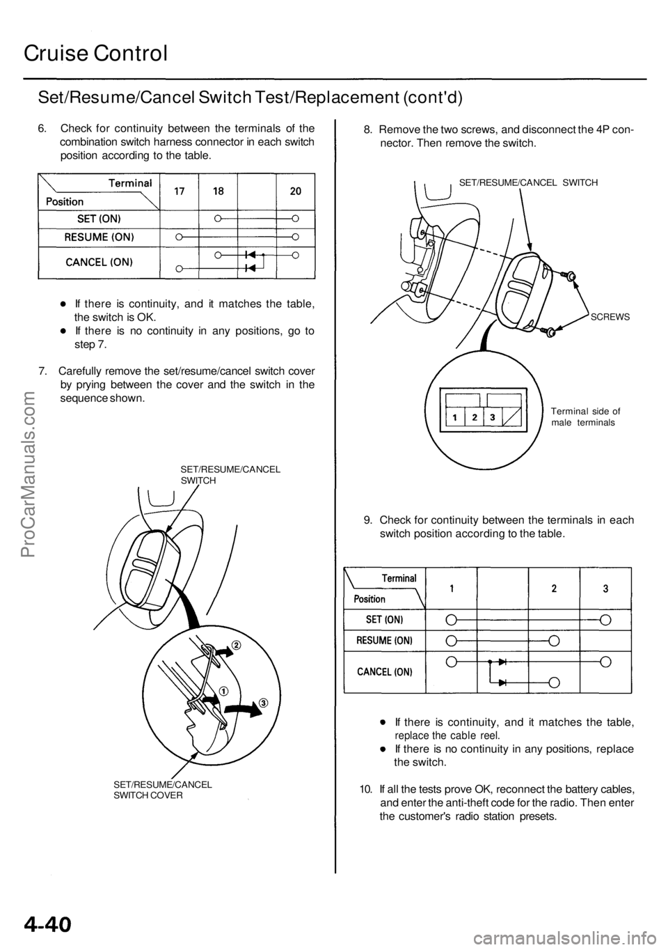
Cruise Control
Set/Resume/Cancel Switch Test/Replacement (cont'd)
6. Check for continuity between the terminals of the
combination switch harness connector in each switch
position according to the table.
If there is continuity, and it matches the table,
the switch is OK.
If there is no continuity in any positions, go to
step 7.
7. Carefully remove the set/resume/cancel switch cover
by prying between the cover and the switch in the
sequence shown.
SET/RESUME/CANCEL
SWITCH
SET/RESUME/CANCEL
SWITCH COVER
8. Remove the two screws, and disconnect the 4P con-
nector. Then remove the switch.
SET/RESUME/CANCEL SWITCH
SCREWS
9. Check for continuity between the terminals in each
switch position according to the table.
If there is continuity, and it matches the table,
replace the cable reel.
If there is no continuity in any positions, replace
the switch.
10. If all the tests prove OK, reconnect the battery cables,
and enter the anti-theft code for the radio. Then enter
the customer's radio station presets.
Terminal side of
male terminalsProCarManuals.com
Page 359 of 1954
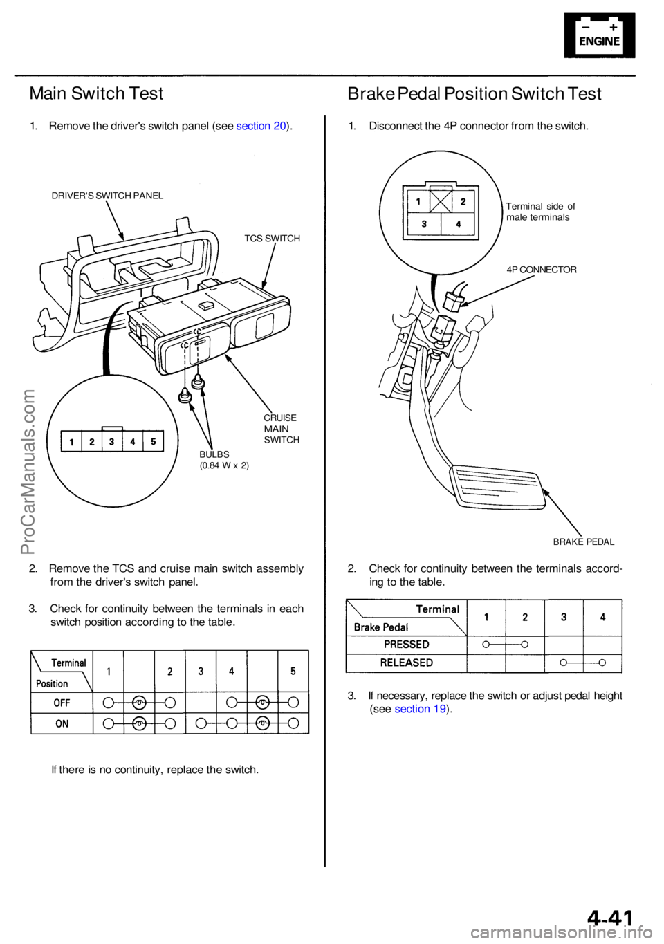
Main Switc h Tes t
1. Remov e th e driver' s switc h pane l (se e sectio n 20 ).
DRIVER' S SWITC H PANE L
TCS SWITC H
CRUISEMAINSWITC H
BULBS(0.84 W x 2)
2. Remov e th e TC S an d cruis e mai n switc h assembl y
fro m th e driver' s switc h panel .
3 . Chec k fo r continuit y betwee n th e terminal s i n eac h
switc h positio n accordin g to th e table .
I f ther e is n o continuity , replac e th e switch .
Brake Peda l Positio n Switc h Tes t
1. Disconnec t th e 4 P connecto r fro m th e switch .
Termina l sid e o fmal e terminal s
4P CONNECTO R
BRAKE PEDA L
2. Chec k fo r continuit y betwee n th e terminal s accord -
in g t o th e table .
3 . I f necessary , replac e th e switc h o r adjus t peda l heigh t
(see section 19 ).
ProCarManuals.com
Page 360 of 1954
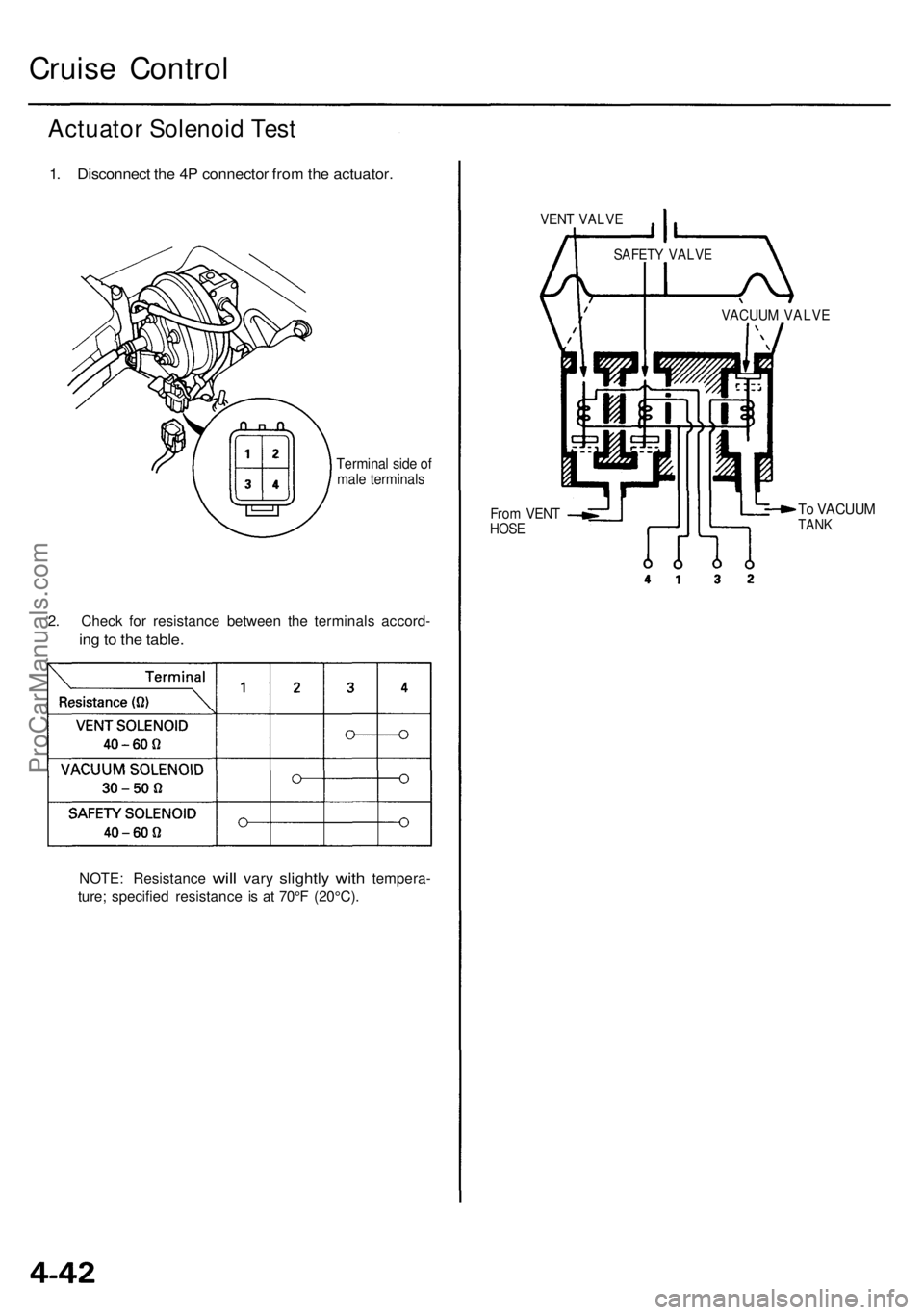
Cruise Control
Actuator Solenoid Test
1. Disconnect the 4P connector from the actuator.
Terminal side of
male terminals
2. Check for resistance between the terminals accord-
ing to the table.
NOTE: Resistance
will
vary
slightly
with
tempera-
ture; specified resistance is at 70°F (20°C).
VENT VALVE
From VENT
HOSE
To VACUUM
TANK
VACUUM VALVE
SAFETY VALVEProCarManuals.com