ACURA RL KA9 1996 Service Repair Manual
Manufacturer: ACURA, Model Year: 1996, Model line: RL KA9, Model: ACURA RL KA9 1996Pages: 1954, PDF Size: 61.44 MB
Page 471 of 1954
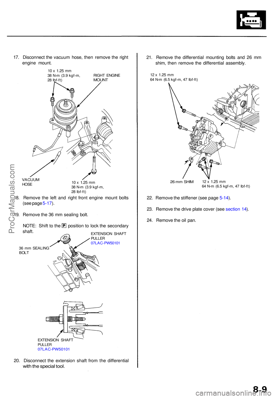
20. Disconnec t th e extensio n shaf t fro m th e differentia l
with th e specia l tool .
EXTENSIO N SHAF TPULLE R07LAC-PW5010 1
36 m m SEALIN G
BOL T EXTENSIO
N SHAF T
PULLE R07LAC-PW5010 1
18. Remov e th e lef t an d righ t fron t engin e moun t bolt s
(se e pag e 5-17 ).
19 . Remov e th e 3 6 m m sealin g bolt .
NOTE : Shif t t o th e
shaft . positio
n t o loc k th e secondar y
VACUUMHOSE10 x 1.2 5 mm38 N- m (3. 9 kgf-m ,
2 8 Ibf-ft )
17. Disconnec t th e vacuu m hose , the n remov e th e righ t
engin e mount .
10 x 1.2 5 mm38 N- m (3. 9 kgf-m ,
2 8 Ibf-ft ) RIGH
T ENGIN EMOUNT
21. Remov e th e differentia l mountin g bolt s an d 2 6 m m
shim , the n remov e th e differentia l assembly .
12 x 1.2 5 mm64 N- m (6. 5 kgf-m , 4 7 Ibf-ft )
22. Remov e th e stiffene r (se e pag e 5-14 ).
23 . Remov e th e driv e plat e cove r (se e sectio n 14 ).
24 . Remov e th e oi l pan .
26 m m SHI M12 x 1.2 5 mm64 N- m (6. 5 kgf-m , 4 7 Ibf-ft )
ProCarManuals.com
Page 472 of 1954
Oil Pan
Installation
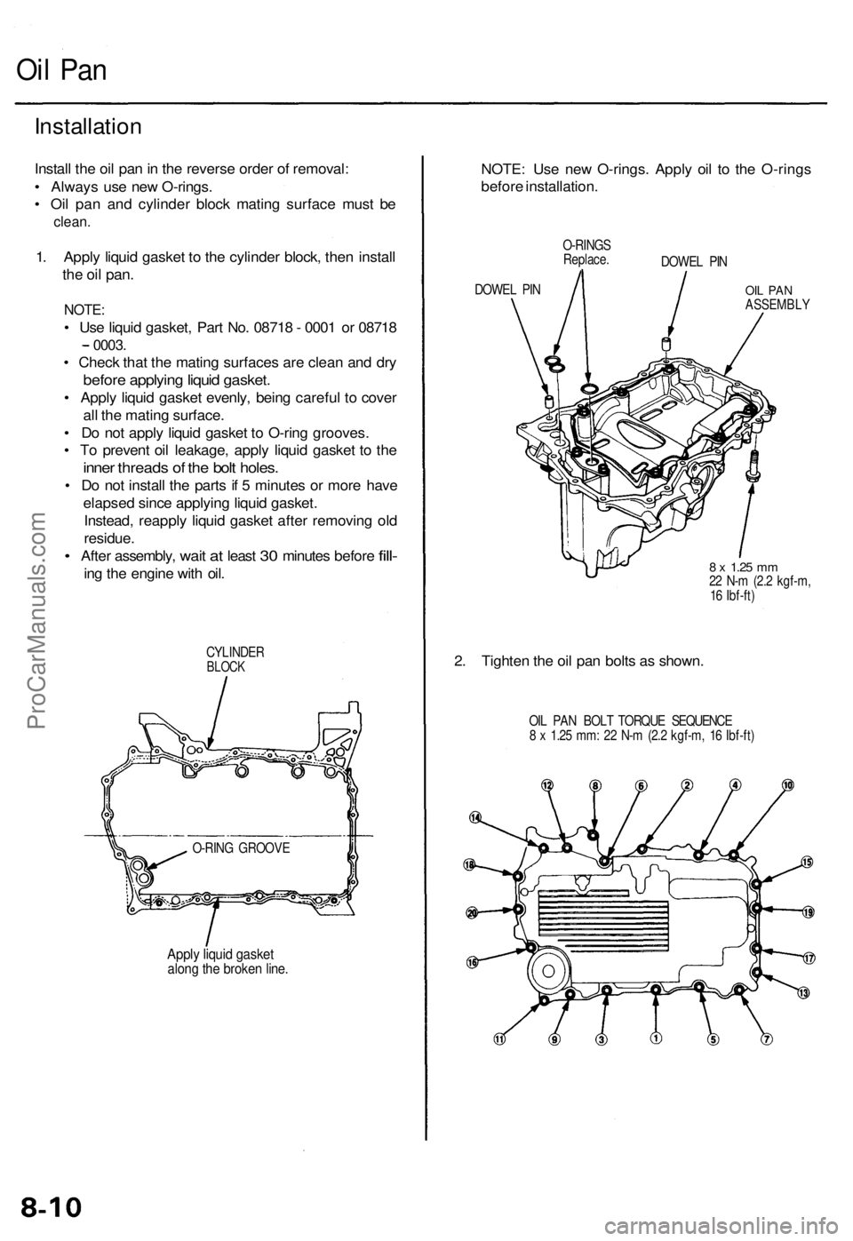
Install the oil pan in the reverse order of removal:
• Always use new O-rings.
• Oil pan and cylinder block mating surface must be
clean.
1. Apply liquid gasket to the cylinder block, then install
the oil
pan.
NOTE:
• Use liquid gasket, Part No. 08718 - 0001 or 08718
0003.
• Check that the mating surfaces are clean and dry
before applying liquid gasket.
• Apply liquid gasket evenly, being careful to cover
all the mating surface.
• Do not apply liquid gasket to O-ring grooves.
• To prevent oil leakage, apply liquid gasket to the
inner threads of the bolt holes.
• Do not install the parts if 5 minutes or more have
elapsed since applying liquid gasket.
Instead, reapply liquid gasket after removing old
residue.
•
After assembly,
wait
at
least
30
minutes before
fill-
ing the engine with oil.
CYLINDER
BLOCK
O-RING GROOVE
Apply liquid gasket
along the broken line.
NOTE: Use new O-rings. Apply oil to the O-rings
before installation.
DOWEL PIN
O-RINGS
Replace.
DOWEL PIN
OIL PAN
ASSEMBLY
8 x
1.25
mm
22 N-m (2.2 kgf-m,
16 Ibf-ft)
2. Tighten the oil pan bolts as shown.
OIL PAN BOLT TORQUE SEQUENCE
8 x 1.25 mm: 22 N-m (2.2 kgf-m, 16 Ibf-ft)ProCarManuals.com
Page 473 of 1954
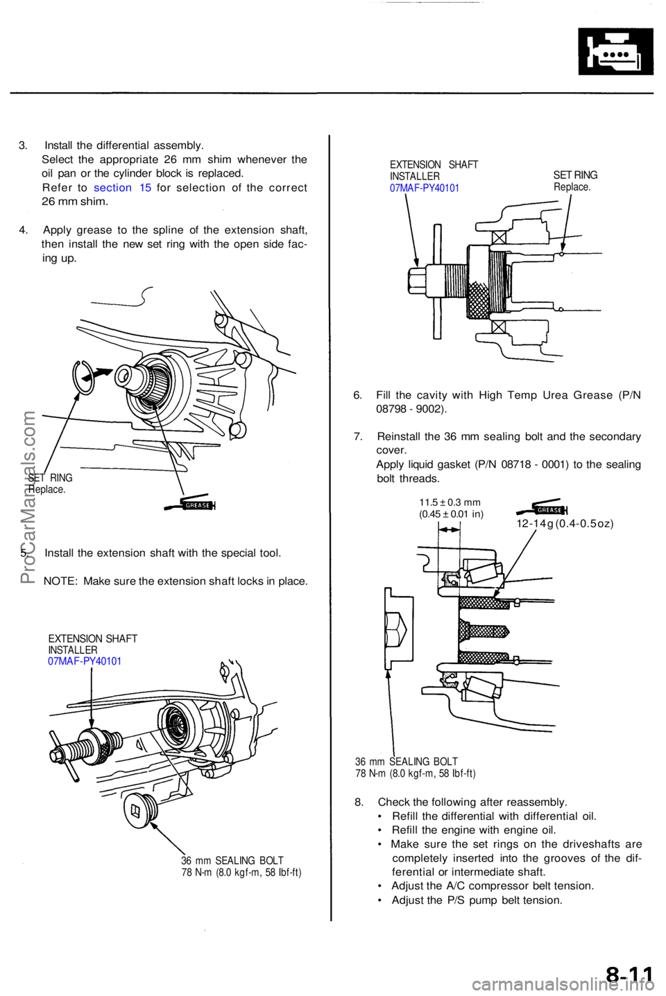
3. Instal l th e differentia l assembly .
Selec t th e appropriat e 2 6 m m shi m wheneve r th e
oi l pa n o r th e cylinde r bloc k i s replaced .
Refe r t o sectio n 1 5 fo r selectio n o f th e correc t
26 m m shim .
4. Appl y greas e t o th e splin e o f th e extensio n shaft ,
the n instal l th e ne w se t rin g wit h th e ope n sid e fac -
ing up .
EXTENSIO N SHAF T
INSTALLE R
07MA F-PY4010 1SET RIN GReplace .
6. Fil l th e cavit y wit h Hig h Tem p Ure a Greas e (P/ N
0879 8 - 9002) .
7 . Reinstal l th e 3 6 m m sealin g bol t an d th e secondar y
cover .
Appl y liqui d gaske t (P/ N 0871 8 - 0001 ) t o th e sealin g
bol t threads .
11.5 ± 0. 3 m m(0.4 5 ± 0.01 in)12 -1 4 g (0.4-0. 5 oz )
36 m m SEALIN G BOL T
7 8 N- m (8. 0 kgf-m , 5 8 Ibf-ft )
8. Chec k th e followin g afte r reassembly .
• Refil l th e differentia l wit h differentia l oil .
• Refil l th e engine with engin e oil .
• Mak e sur e th e se t ring s o n th e driveshaft s ar e
completel y inserte d int o th e groove s o f th e dif -
ferentia l o r intermediat e shaft .
• Adjus t th e A/ C compresso r bel t tension .
• Adjus t th e P/ S pum p bel t tension .
36 m m SEALIN G BOL T
7 8 N- m (8. 0 kgf-m , 5 8 Ibf-ft )
EXTENSIO N SHAF TINSTALLE R07MAF-PY4010 1
5. Instal l th e extensio n shaf t wit h th e specia l tool .
NOTE : Mak e sur e th e extensio n shaf t lock s in place .
SET RIN G
Replace .
ProCarManuals.com
Page 474 of 1954
Oil Pum p
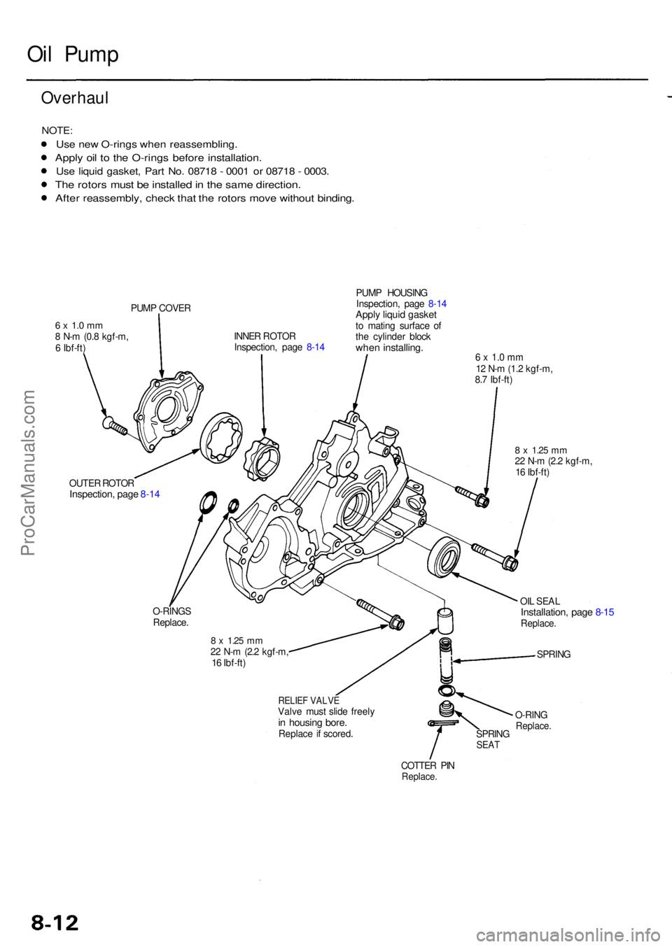
Overhau l
NOTE:
Use ne w O-ring s whe n reassembling .
Apply oi l t o th e O-ring s befor e installation .
Use liqui d gasket , Par t No . 0871 8 - 000 1 o r 0871 8 - 0003 .
The rotor s mus t b e installe d in th e sam e direction .
After reassembly , chec k tha t th e rotor s mov e withou t binding .
6 x 1. 0 m m8 N- m (0. 8 kgf-m ,
6 Ibf-ft ) PUM
P COVE R
INNER ROTO R
Inspection , pag e 8-1 4 PUM
P HOUSIN G
Inspection , pag e 8-1 4
Appl y liqui d gaske tto matin g surfac e o f
th e cylinde r bloc k
when installing .6 x 1. 0 m m12 N- m (1. 2 kgf-m ,
8. 7 Ibf-ft )
8 x 1.2 5 mm22 N- m (2. 2 kgf-m ,
1 6 Ibf-ft )
OI L SEA L
Installation , pag e 8-1 5Replace .
SPRING
O-RIN G
Replace .SPRINGSEAT
COTTE R PI NReplace .
RELIEF VALV EValve mus t slid e freel yin housin g bore .Replac e if scored .
8 x 1.2 5 mm22 N- m (2. 2 kgf-m ,
1 6 Ibf-ft )
O-RING
S
Replace .
OUTE
R ROTO R
Inspection , pag e 8-1 4
ProCarManuals.com
Page 475 of 1954
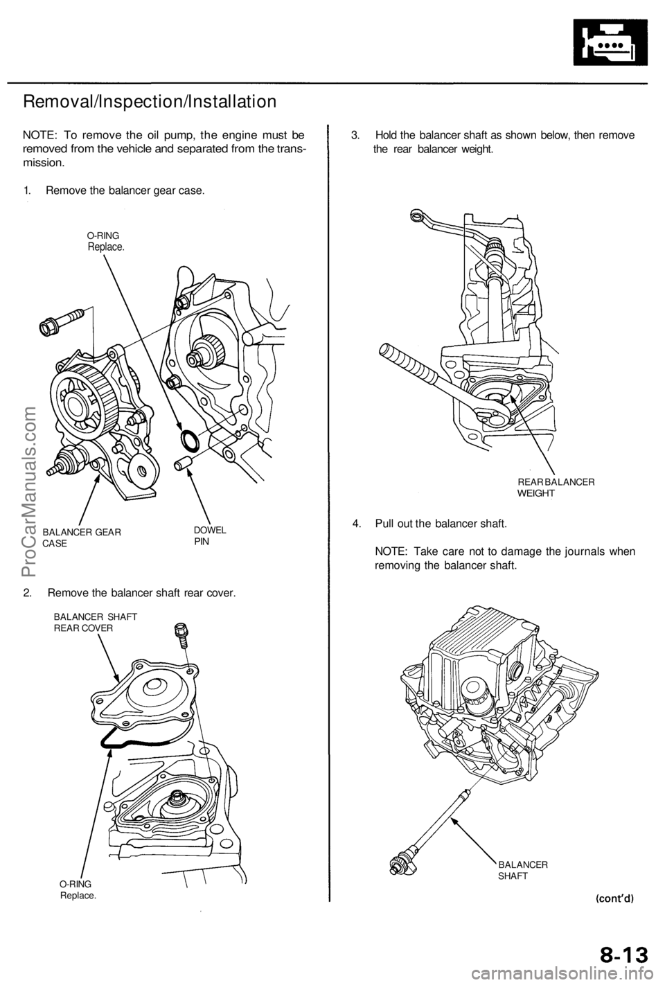
Removal/lnspection/lnstallation
NOTE: To remove the oil pump, the engine must be
removed from the vehicle and separated from the trans-
mission.
1. Remove the balancer gear case.
O-RING
Replace.
BALANCER GEAR
CASE
DOWEL
PIN
2. Remove the balancer shaft rear cover.
BALANCER SHAFT
REAR COVER
O-RING
Replace.
BALANCER
SHAFT
3. Hold the balancer shaft as shown below, then remove
the rear balancer weight.
4. Pull out the balancer shaft.
NOTE: Take care not to damage the journals when
removing the balancer shaft.
REAR BALANCER
WEIGHTProCarManuals.com
Page 476 of 1954
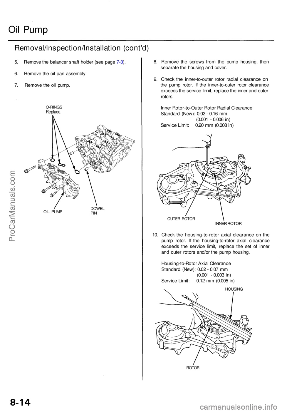
Oil Pum p
Removal/lnspection/lnstallatio n (cont'd )
5. Remov e th e balance r shaf t holde r (se e pag e 7-3 ).
6 . Remov e th e oi l pa n assembly .
7 . Remov e th e oi l pump .
O-RING SReplace .
OIL PUM PDOWE LPIN
ROTO R
HOUSIN G
Housing-to-Roto r Axia l Clearanc e
Standar d (New) : 0.0 2 - 0.0 7 m m
(0.00 1 - 0.00 3 in )
Servic e Limit : 0.1 2 m m (0.00 5 in )
10
. Chec k th e housing-to-roto r axia l clearanc e o n th e
pum p rotor . I f th e housing-to-roto r axia l clearanc e
exceed s th e servic e limit , replac e th e se t o f inne r
an d oute r rotor s and/o r th e pum p housing .
8
. Remov e th e screw s fro m th e pum p housing , the n
separat e th e housin g an d cover .
9. Chec k th e inner-to-oute r roto r radia l clearanc e o n
the pum p rotor . I f th e inner-to-oute r roto r clearanc e
exceed s
the servic e limit, replac e the inne r and oute r
rotors .
Inne r Rotor-to-Oute r Roto r Radia l Clearanc e
Standar d (New) : 0.0 2 - 0.1 6 m m
(0.00 1 - 0.00 6 in )
Servic e Limit : 0.2 0 m m (0.00 8 in )
OUTE R ROTO RINNER ROTO R
ProCarManuals.com
Page 477 of 1954
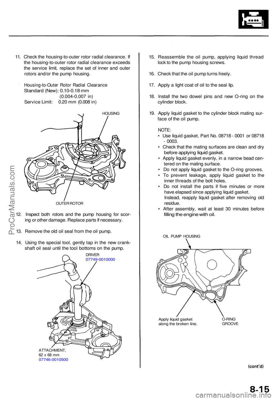
11. Chec k th e housing-to-oute r roto r radia l clearance . I f
th e housing-to-oute r roto r radia l clearanc e exceed s
th e servic e limit , replac e th e se t o f inne r an d oute r
rotor s and/o r th e pum p housing .
Housing-to-Oute r Roto r Radia l Clearanc e
Standard (New) : 0.10-0.1 8 m m
(0.004-0.00 7 in )
Servic e Limit : 0.2 0 m m (0.00 8 in )
HOUSIN G
12. Inspec t bot h rotor s an d th e pum p housin g fo r scor -
in g o r othe r damage . Replac e part s if necessary .
13 . Remov e th e ol d oi l sea l fro m th e oi l pump .
14 . Usin g th e specia l tool , gentl y ta p in th e ne w crank -
shaf t oi l sea l unti l th e too l bottom s o n th e pump .
OUTER ROTO R
DRIVE R07749-001000 0
ATTACHMENT ,62 x 68 m m07746-001050 0
Apply liqui d gaske talong th e broke n line .O-RIN GGROOV E
OIL PUM P HOUSIN G
15. Reassembl e th e oi l pump , applyin g liqui d threa d
loc k to th e pum p housin g screws .
16 . Chec k tha t th e oi l pum p turn s freely .
17 . Appl y a ligh t coa t o f oi l t o th e sea l lip .
18 . Instal l th e tw o dowe l pin s an d ne w O-rin g o n th e
cylinde r block .
19 . Appl y liqui d gaske t t o th e cylinde r bloc k matin g sur -
fac e o f th e oi l pump .
NOTE:
• Us e liqui d gasket , Par t No . 0871 8 - 000 1 o r 0871 8
- 0003 .
• Chec k tha t th e matin g surface s ar e clea n an d dr y
befor e applyin g liqui d gasket .
• Appl y liqui d gaske t evenly , i n a narro w bea d cen -
tere d o n th e matin g surface .
• D o no t appl y liqui d gaske t t o th e O-rin g grooves .
• T o preven t leakage , appl y liqui d gaske t t o th e
inne r thread s o f th e bol t holes .
• D o no t instal l th e part s i f fiv e minute s o r mor e
hav e elapse d sinc e applyin g liqui d gasket .
Instead , reappl y liqui d gaske t afte r removin g ol d
residue .
• Afte r assembly , wai t a t leas t 3 0 minute s befor e
filling th e engin e wit h oil .
ProCarManuals.com
Page 478 of 1954
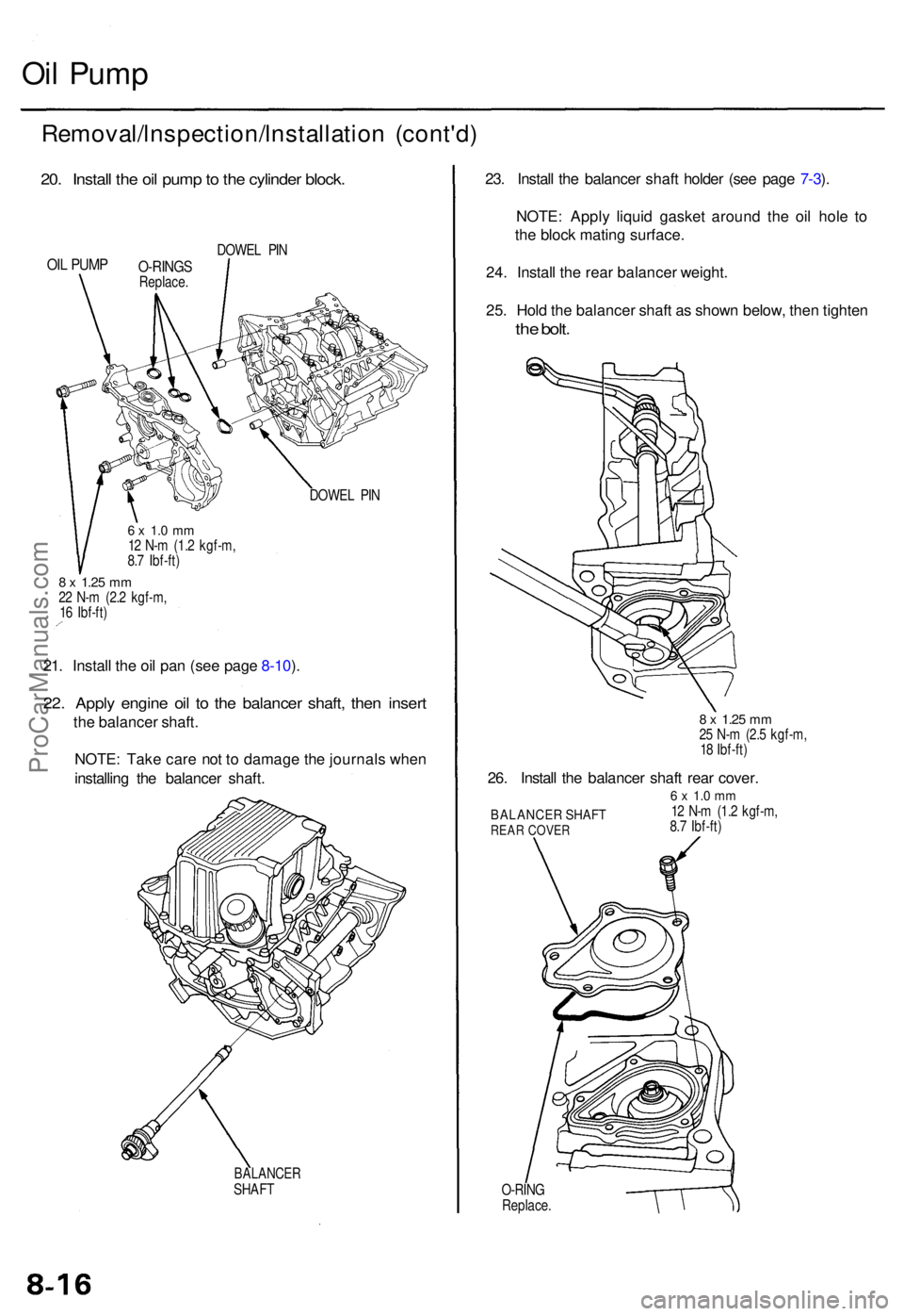
Oil Pum p
Removal/lnspection/lnstallatio n (cont'd )
20. Instal l th e oi l pum p to th e cylinde r block .
OIL PUM PO-RING SReplace .DOWE
L PI N
DOWE L PI N
6 x 1. 0 m m12 N- m (1. 2 kgf-m ,
8. 7 Ibf-ft )
8 x 1.2 5 mm22 N- m (2. 2 kgf-m ,
1 6 Ibf-ft )
21. Instal l th e oi l pa n (se e pag e 8-10 ).
22 . Appl y engin e oi l t o th e balance r shaft , the n inser t
the balance r shaft .
NOTE : Tak e car e no t t o damag e th e journal s whe n
installin g th e balance r shaft .
BALANCE RSHAFT
O-RING
Replace .
BALANCE R SHAF TREAR COVE R
6 x 1. 0 m m12 N- m (1. 2 kgf-m ,
8. 7 Ibf-ft )
23. Instal l th e balance r shaf t holde r (se e pag e 7-3 ).
NOTE : Appl y liqui d gaske t aroun d th e oi l hol e t o
th e bloc k matin g surface .
24 . Instal l th e rea r balance r weight .
25 . Hol d th e balance r shaf t a s show n below , the n tighte n
the bolt .
8 x 1.2 5 mm25 N- m (2. 5 kgf-m ,
1 8 Ibf-ft )
26. Instal l th e balance r shaf t rea r cover .
ProCarManuals.com
Page 479 of 1954
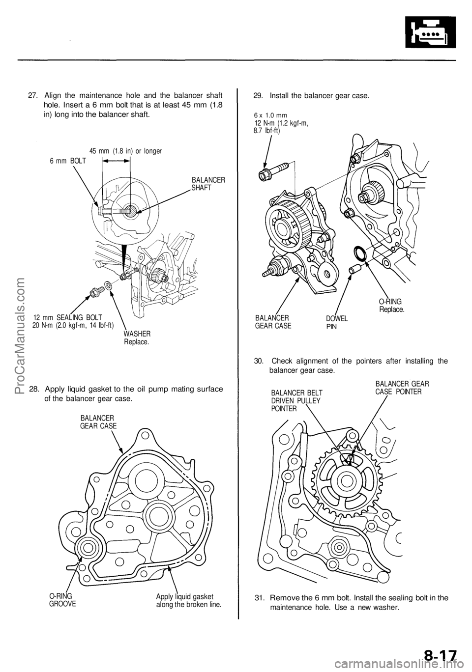
31. Remov e th e 6 m m bolt . Instal l th e sealin g bol t i n th e
maintenanc e hole . Us e a ne w washer .
Apply liqui d gaske talong th e broke n line .O-RIN GGROOV E
27. Alig n th e maintenanc e hol e an d th e balance r shaf t
hole. Inser t a 6 mm bol t tha t i s a t leas t 4 5 m m (1. 8
in) lon g int o th e balance r shaft .
6 m m BOL T4
5 m m (1. 8 in ) o r longe r
BALANCER
SHAF T
1 2 m m SEALIN G BOL T
2 0 N- m (2. 0 kgf-m , 1 4 Ibf-ft )
WASHE R
Replace .
28. Appl y liqui d gaske t t o th e oi l pum p matin g surfac e
of th e balance r gea r case .
BALANCE R
GEA R CAS E
29. Instal l th e balance r gea r case .
6 x 1. 0 m m12 N- m (1. 2 kgf-m ,
8. 7 Ibf-ft )
BALANCE R
GEA R CAS E DOWE
L
PIN
O-RIN GReplace .
30. Chec k alignmen t o f th e pointer s afte r installin g th e
balance r gea r case .
BALANCE R BEL T
DRIVE N PULLE Y
POINTE R BALANCE
R GEA R
CAS E POINTE R
ProCarManuals.com
Page 480 of 1954
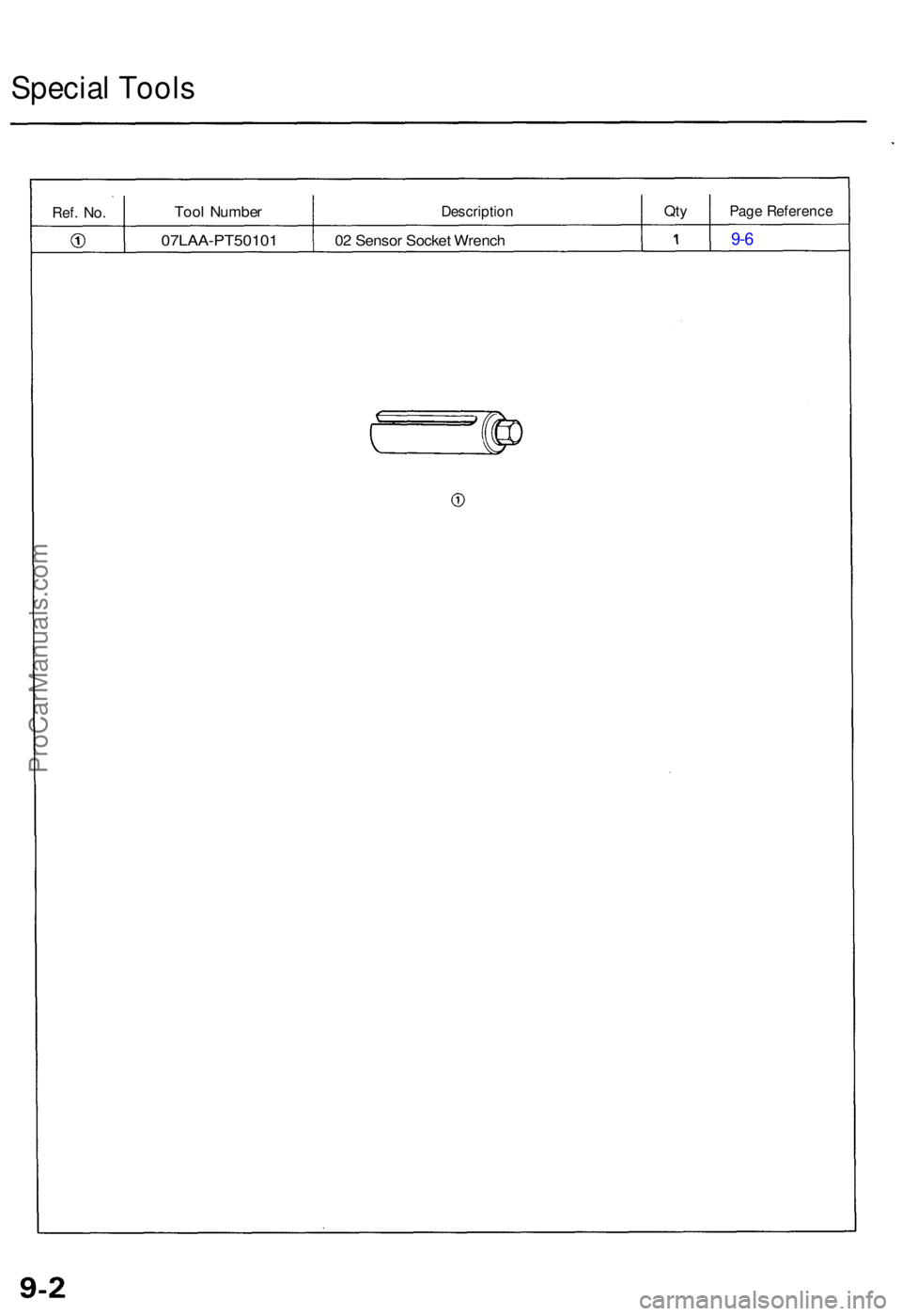
Special Tool s
Ref. No .Too l Numbe rDescriptio nQtyPag e Referenc e
07LAA-PT5010 1 02 Senso r Socke t Wrenc h 9- 6
ProCarManuals.com