ACURA TL 1995 Service Repair Manual
Manufacturer: ACURA, Model Year: 1995, Model line: TL, Model: ACURA TL 1995Pages: 1771, PDF Size: 62.49 MB
Page 921 of 1771
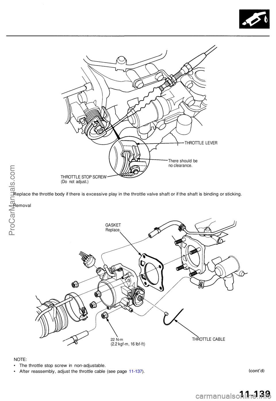
THROTTLE LEVE R
There shoul d b e
n o clearance .
THROTTL E STO P SCRE W
(D o no t adjust. )
Replace th e throttl e bod y if ther e is excessiv e pla y i n th e throttl e valv e shaf t o r i f th e shaf t i s bindin g o r sticking .
Remova l
GASKETReplace .
22 N- m(2.2 kgf-m , 1 6 Ibf-ft )
NOTE :
• Th e throttl e sto p scre w in non-adjustable .
• Afte r reassembly , adjus t th e throttl e cabl e (se e pag e 11-137 ).
THROTTL E CABL E
ProCarManuals.com
Page 922 of 1771
Intake Air System
Throttle Body (cont'd)
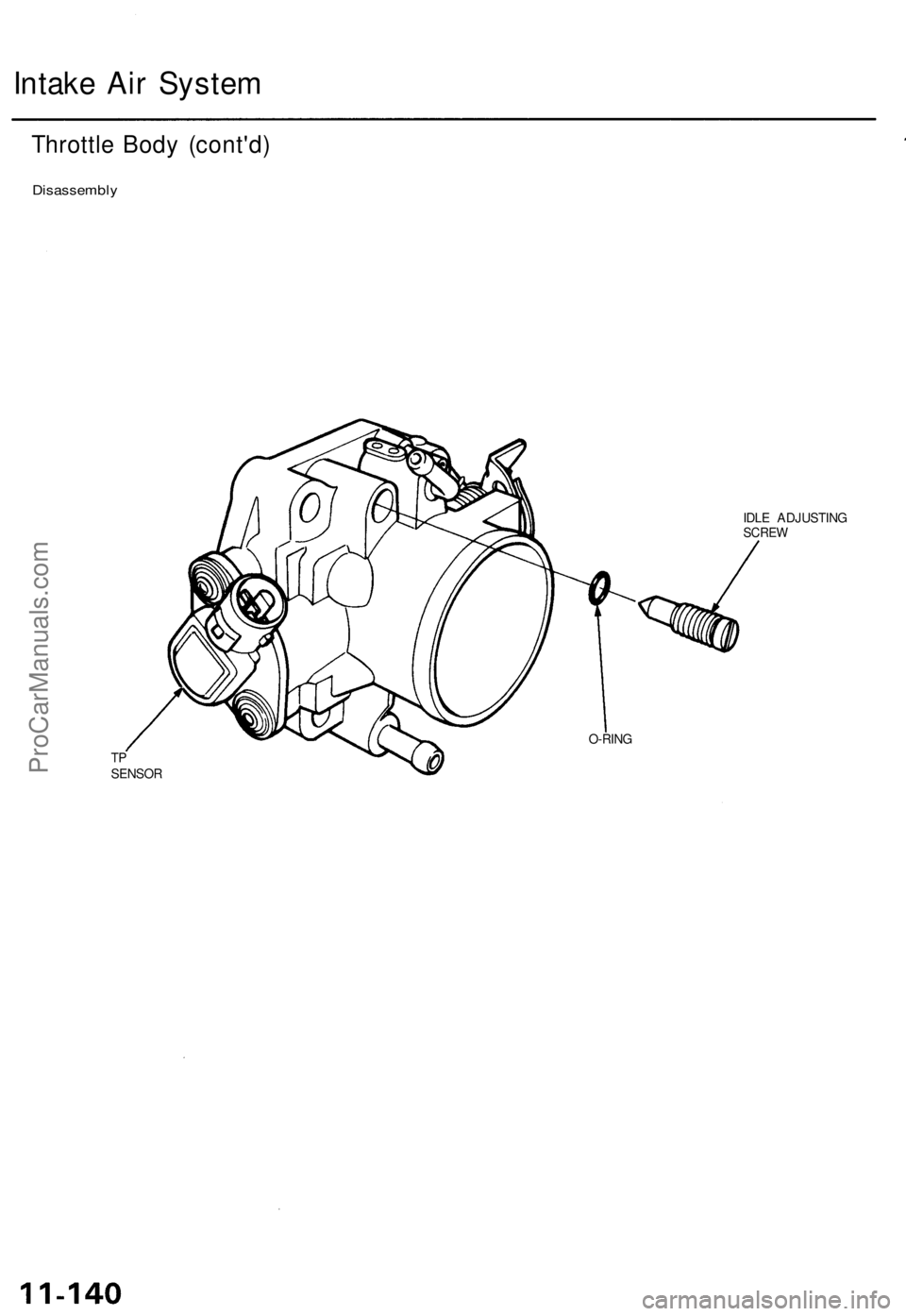
Disassembly
IDLE ADJUSTING
SCREW
O-RING
TP
SENSORProCarManuals.com
Page 923 of 1771
Intake Air Bypass (IAB) Control System
Description
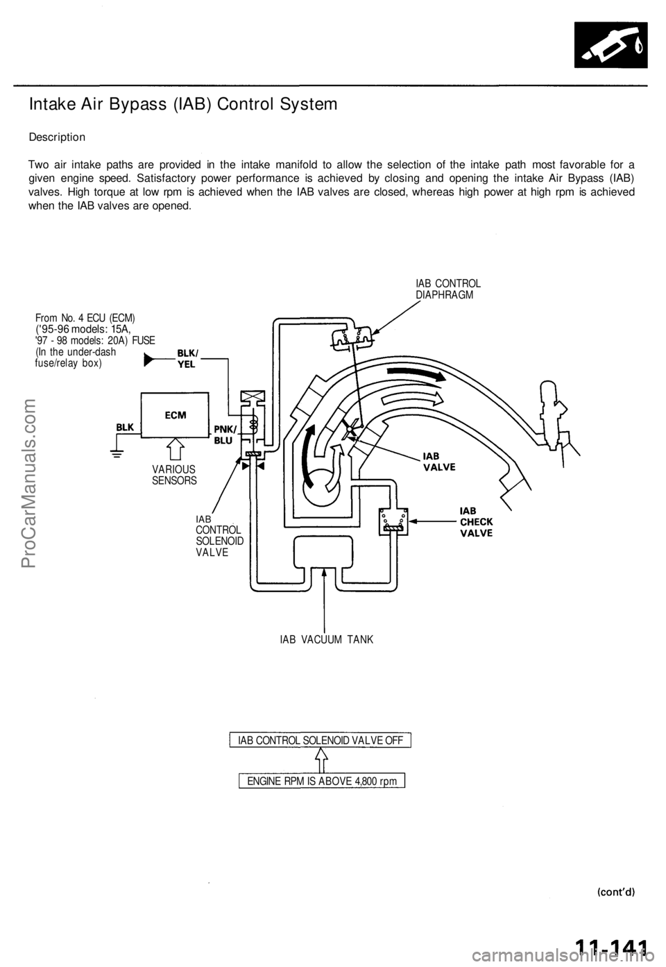
Two air intake paths are provided in the intake manifold to allow the selection of the intake path most favorable for a
given engine speed. Satisfactory power performance is achieved by closing and opening the intake Air Bypass (IAB)
valves. High torque at low rpm is achieved when the IAB valves are closed, whereas high power at high rpm is achieved
when the IAB valves are opened.
IAB CONTROL
DIAPHRAGM
From No. 4 ECU (ECM)
('95-96 models: 15A,
'97 - 98 models: 20A) FUSE
(In the under-dash
fuse/relay box)
VARIOUS
SENSORS
IAB
CONTROL
SOLENOID
VALVE
IAB VACUUM TANK
IAB CONTROL SOLENOID VALVE OFF
ENGINE RPM IS ABOVE 4,800 rpmProCarManuals.com
Page 924 of 1771
Intake Ai r Syste m
Intake Ai r Bypas s (IAB ) Contro l Syste m (cont'd )
Troubleshootin g
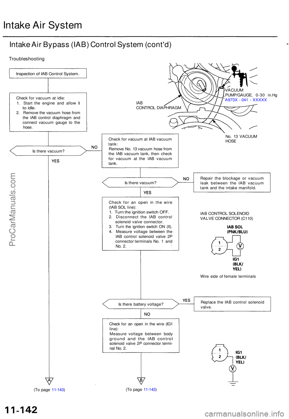
Is ther e vacuum ?
IABCONTRO L DIAPHRAG M
VACUUMPUMP/GAUGE , 0-3 0 in.H g
A973 X - 04 1 - XXXX X
Chec k fo r vacuu m at IA B vacuu m
tank :
Remov e No . 1 3 vacuu m hos e fro m
th e IA B vacuu m tank , the n chec k
fo r vacuu m a t th e IA B vacuu m
tank .
Is ther e vacuum ? Repai
r th e blockag e o r vacuu m
lea k betwee n th e IA B vacuu m
tan k an d th e intak e manifold .
Chec k fo r a n ope n i n th e wir e
(IA B SO L line) :
1. Tur n th e ignitio n switc h OFF .2. Disconnec t th e IA B contro l
solenoi d valv e connector .
3 . Tur n th e ignitio n switc h O N (II) .
4 . Measur e voltag e betwee n th e
IA B contro l solenoi d valv e 2 P
connecto r terminal s No . 1 an d
No. 2 .
IA B CONTRO L SOLENOI D
VALV E CONNECTO R (C110 )
Wir e sid e o f femal e terminal s
I s ther e batter y voltage ? Replac
e th e IA B contro l solenoi d
valve.
Check fo r a n ope n in th e wir e (IG 1line) :Measur e voltag e betwee n bod ygroun d an d th e IA B contro lsolenoid valv e 2 P connecto r termi -nal No . 2 .
(T o pag e 11-143 ) (T
o pag e 11-143 )
Inspectio n o f IA B Contro l System .
Check fo r vacuu m at idle :
1 . Star t th e engin e an d allo w i t
to idle .2. Remov e th e vacuu m hos e fro m
th e IA B contro l diaphrag m an d
connec t vacuu m gaug e t o th e
hose .
No. 1 3 VACUU M
HOSE
ProCarManuals.com
Page 925 of 1771
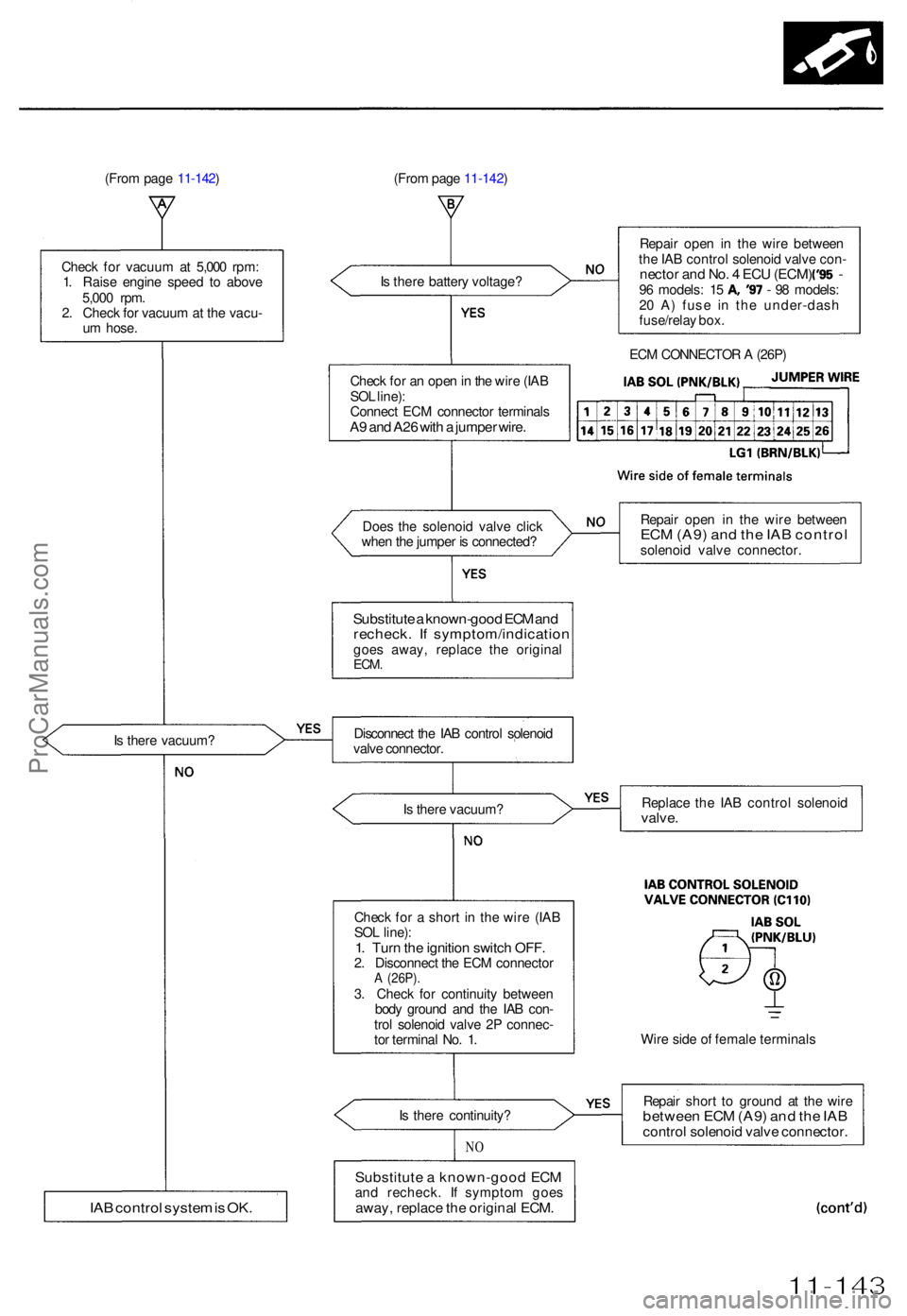
(From pag e 11-142 ) (From pag e 11-142 )
I s ther e batter y voltage ? Repai
r ope n i n th e wir e betwee n
th e IA B contro l solenoi d valv e con -
necto r an d No . 4 EC U (ECM ) ('95 -96 models : 1 5 A , '9 7 - 9 8 models :
2 0 A ) fus e i n th e under-das h
fuse/rela y box .
Chec k fo r a n ope n in th e wir e (IA B
SO L line) :
Connec t EC M connecto r terminal s
A9 an d A2 6 wit h a jumpe r wire .
Doe s th e solenoi d valv e clic k
whe n th e jumpe r i s connected ?
Substitute a known-goo d EC M an drecheck . I f symptom/indicatio ngoes away , replac e th e origina lECM.
Is ther e vacuum ?
Chec k fo r a shor t i n th e wir e (IA B
SO L line) :
1. Tur n th e ignitio n switc h OFF .2. Disconnec t th e EC M connecto rA (26P) .3. Chec k fo r continuit y betwee n
bod y groun d an d th e IA B con -
tro l solenoi d valv e 2 P connec -
to r termina l No . 1 .
I s ther e continuity ?
NO
Substitut e a known-goo d EC Mand recheck . I f sympto m goe saway, replac e th e origina l ECM .
Repai r ope n i n th e wir e betwee nECM (A9 ) an d th e IA B contro lsolenoid valv e connector .
Replac e th e IA B contro l solenoi d
valve.
Wire sid e o f femal e terminal s
Repai r shor t t o groun d a t th e wir e
betwee n EC M (A9 ) an d th e IA Bcontro l solenoi d valv e connector .
11-143
Check fo r vacuu m a t 5,00 0 rpm :
1 . Rais e engin e spee d t o abov e
5,00 0 rpm .
2 . Chec k fo r vacuu m a t th e vacu -
u m hose .
I s ther e vacuum ? Disconnec
t th e IA B contro l solenoi d
valv e connector .
IAB contro l syste m is OK .
ECM CONNECTO R A (26P )
ProCarManuals.com
Page 926 of 1771
Intake Ai r Syste m Emissio
n Contro l Syste m
Intake Ai r Bypas s (IAB ) Contro l
Syste m (cont'd )
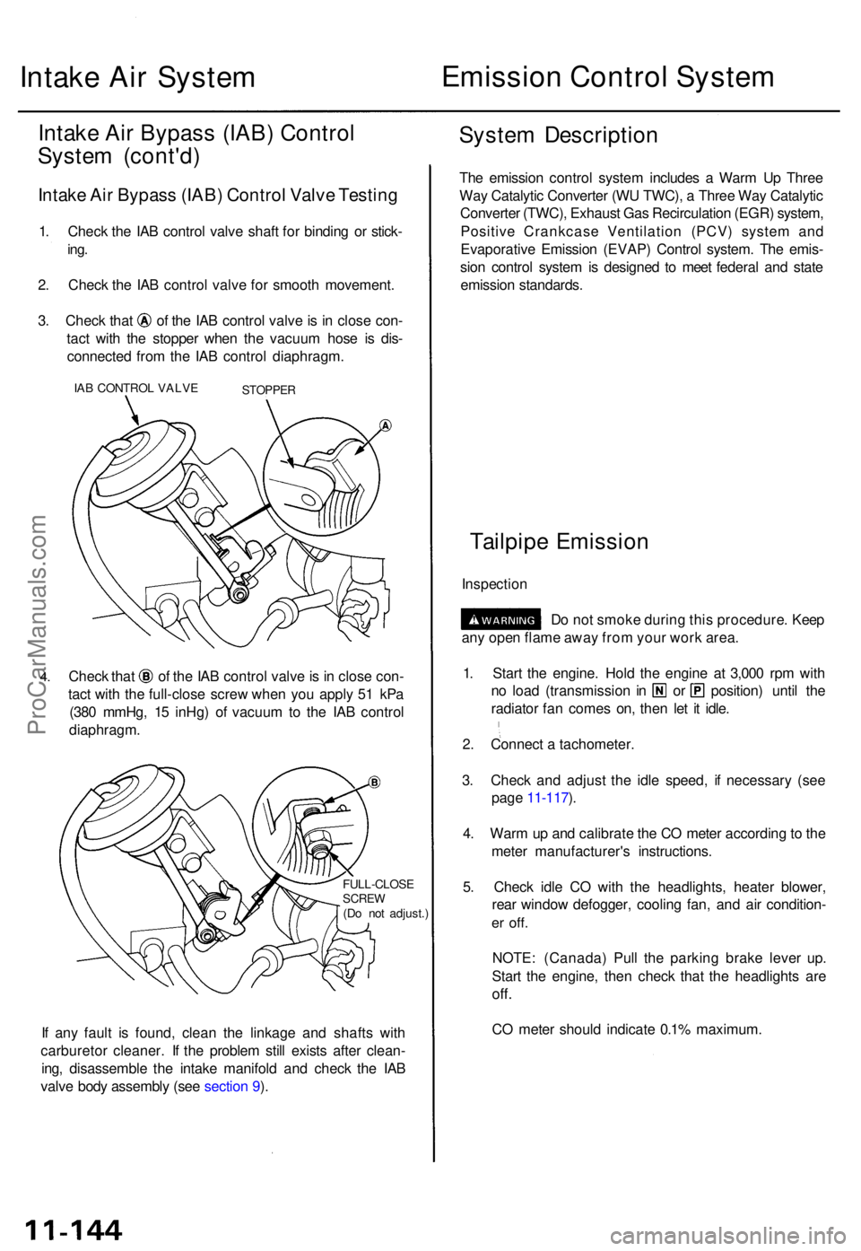
Intake Ai r Bypas s (IAB ) Contro l Valv e Testin g
1. Chec k th e IA B contro l valv e shaf t fo r bindin g o r stick -
ing.
2. Chec k th e IA B contro l valv e fo r smoot h movement .
3. Chec k tha t o f th e IA B contro l valv e is i n clos e con -
tac t wit h th e stoppe r whe n th e vacuu m hos e i s dis -
connecte d fro m th e IA B contro l diaphragm .
IAB CONTRO L VALV ESTOPPE R
4.Chec k tha t o f th e IA B contro l valv e is in clos e con -
tac t wit h th e full-clos e scre w whe n yo u appl y 5 1 kP a
(38 0 mmHg , 1 5 inHg ) o f vacuu m to th e IA B contro l
diaphragm .
FULL-CLOS ESCREW(Do no t adjust. )
If an y faul t i s found , clea n th e linkag e an d shaft s wit h
carbureto r cleaner . I f th e proble m stil l exist s afte r clean -
ing , disassembl e th e intak e manifol d an d chec k th e IA B
valv e bod y assembl y (se e sectio n 9 ).
Syste m Descriptio n
The emissio n contro l syste m include s a War m U p Thre e
Wa y Catalyti c Converte r (W U TWC) , a Thre e Wa y Catalyti c
Converte r (TWC) , Exhaus t Ga s Recirculatio n (EGR ) system ,
Positiv e Crankcas e Ventilatio n (PCV ) syste m an d
Evaporativ e Emissio n (EVAP ) Contro l system . Th e emis -
sio n contro l syste m is designe d t o mee t federa l an d stat e
emissio n standards .
Tailpipe Emissio n
Inspectio n
Do no t smok e durin g thi s procedure . Kee p
an y ope n flam e awa y fro m you r wor k area .
1 . Star t th e engine . Hol d th e engin e a t 3,00 0 rp m wit h
no loa d (transmissio n i n o r position ) unti l th e
radiato r fa n come s on , the n le t i t idle .
2 . Connec t a tachometer .
3 . Chec k an d adjus t th e idl e speed , i f necessar y (se e
pag e 11-117 ).
4 . War m u p an d calibrat e th e C O mete r accordin g to th e
mete r manufacturer' s instructions .
5 . Chec k idl e C O wit h th e headlights , heate r blower ,
rea r windo w defogger , coolin g fan , an d ai r condition -
er off .
NOTE : (Canada ) Pul l th e parkin g brak e leve r up .
Star t th e engine , the n chec k tha t th e headlight s ar e
off.
CO mete r shoul d indicat e 0.1 % maximum .
ProCarManuals.com
Page 927 of 1771
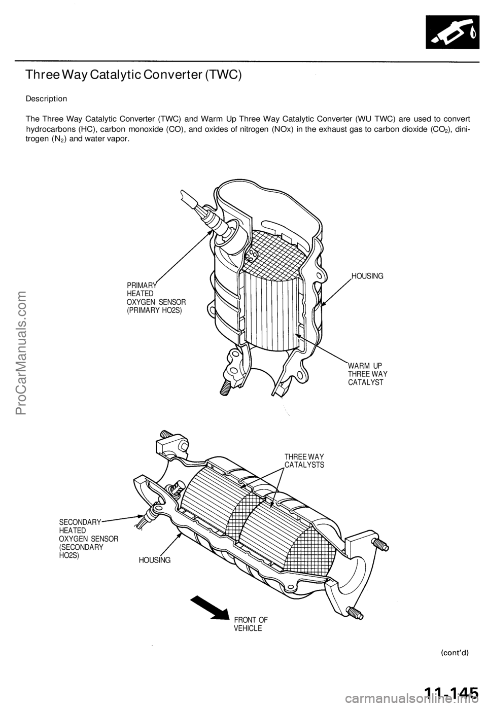
Three Way Catalytic Converter (TWC)
Description
The Three Way Catalytic Converter (TWC) and Warm Up Three Way Catalytic Converter (WU TWC) are used to convert
hydrocarbons (HC), carbon monoxide (CO), and oxides of nitrogen (NOx) in the exhaust gas to carbon dioxide (CO2), dini-
trogen (N2) and water vapor.
PRIMARY
HEATED
OXYGEN SENSOR
(PRIMARY HO2S)
HOUSING
WARM UP
THREE WAY
CATALYST
THREE WAY
CATALYSTS
SECONDARY
HEATED
OXYGEN SENSOR
(SECONDARY
HO2S)
FRONT OF
VEHICLE
HOUSINGProCarManuals.com
Page 928 of 1771
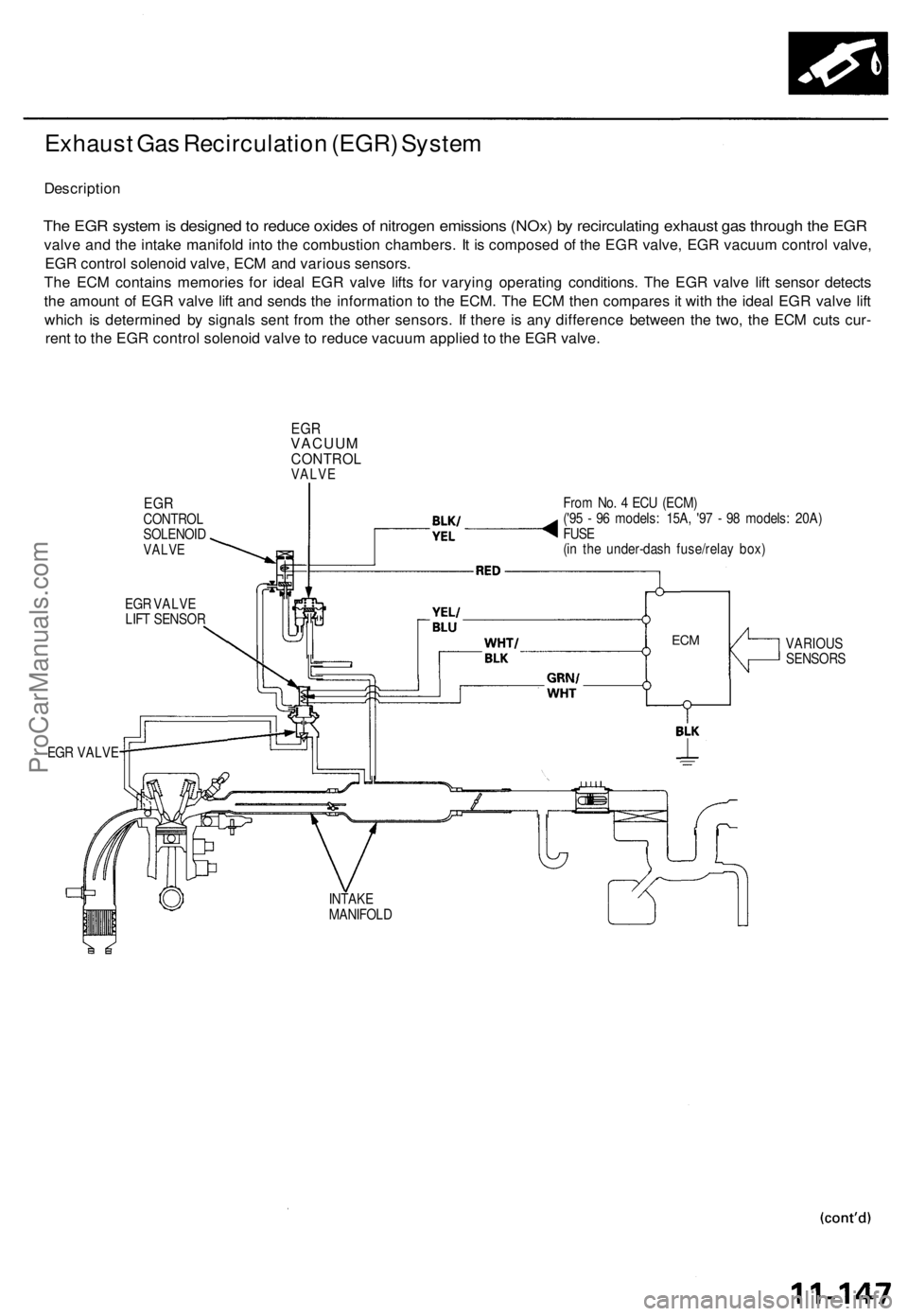
Exhaust Ga s Recirculatio n (EGR ) Syste m
Descriptio n
The EG R syste m is designe d to reduc e oxide s o f nitroge n emission s (NOx ) b y recirculatin g exhaus t ga s throug h th e EG R
valv e an d th e intak e manifol d int o th e combustio n chambers . I t i s compose d o f th e EG R valve , EG R vacuu m contro l valve ,
EG R contro l solenoi d valve , EC M an d variou s sensors .
Th e EC M contain s memorie s fo r idea l EG R valv e lift s fo r varyin g operatin g conditions . Th e EG R valv e lif t senso r detect s
th e amoun t o f EG R valv e lif t an d send s th e informatio n t o th e ECM . Th e EC M the n compare s it wit h th e idea l EG R valv e lif t
whic h i s determine d b y signal s sen t fro m th e othe r sensors . I f ther e i s an y differenc e betwee n th e two , th e EC M cut s cur -
ren t t o th e EG R contro l solenoi d valv e to reduc e vacuu m applie d to th e EG R valve .
EGRVACUU MCONTRO LVALVE
EGRCONTRO L
SOLENOI D
VALVE
EGR VALV E
LIF T SENSO R Fro
m No . 4 EC U (ECM )
('9 5 - 9 6 models : 15A , '9 7 - 9 8 models : 20A )
FUS E
(i n th e under-das h fuse/rela y box )
VARIOU S
SENSOR S
EG R VALV E
INTAKE
MANIFOL D
ECM
ProCarManuals.com
Page 929 of 1771
Positive Crankcase Ventilation (PCV) System
Description
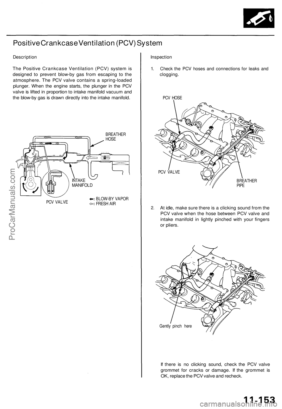
The Positive Crankcase Ventilation (PCV) system is
designed to prevent blow-by gas from escaping to the
atmosphere. The PCV valve contains a spring-loaded
plunger. When the engine starts, the plunger in the PCV
valve is lifted in proportion to intake manifold vacuum and
the blow-by gas is drawn directly into the intake manifold.
BREATHER
HOSE
PCV VALVE
BLOW-BY VAPOR
FRESH AIR
Inspection
1. Check the PCV hoses and connections for leaks and
clogging.
PCV HOSE
PCV VALVE
2.
BREATHER
PIPE
At idle, make sure there is a clicking sound from the
PCV valve when the hose between PCV valve and
intake manifold in lightly pinched with your fingers
or pliers.
Gently pinch here
If there is no clicking sound, check the PCV valve
grommet for cracks or damage. If the grommet is
OK, replace the PCV valve and recheck.
INTAKE
MANIFOLDProCarManuals.com
Page 930 of 1771
Emission Control System
Evaporative Emission (EVAP) Controls
Description
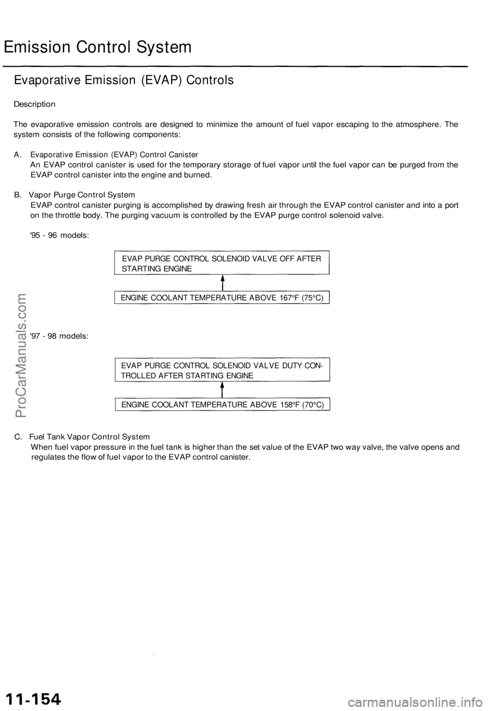
The evaporative emission controls are designed to minimize the amount of fuel vapor escaping to the atmosphere. The
system consists of the following components:
A. Evaporative Emission (EVAP) Control Canister
An EVAP control canister is used for the temporary storage of fuel vapor until the fuel vapor can be purged from the
EVAP control canister into the engine and burned.
B. Vapor Purge Control System
EVAP control canister purging is accomplished by drawing fresh air through the EVAP control canister and into a port
on the throttle body. The purging vacuum is controlled by the EVAP purge control solenoid valve.
'95 - 96 models:
EVAP PURGE CONTROL SOLENOID VALVE OFF AFTER
STARTING ENGINE
'97 - 98 models:
EVAP PURGE CONTROL SOLENOID VALVE DUTY CON-
TROLLED AFTER STARTING ENGINE
C. Fuel Tank Vapor Control System
When fuel vapor pressure in the fuel tank is higher than the set value of the EVAP two way valve, the valve opens and
regulates the flow of fuel vapor to the EVAP control canister.
ENGINE COOLANT TEMPERATURE ABOVE 167°F (75°C)
ENGINE COOLANT TEMPERATURE ABOVE 158°F (70°C)ProCarManuals.com