ACURA TL 1995 Service Repair Manual
Manufacturer: ACURA, Model Year: 1995, Model line: TL, Model: ACURA TL 1995Pages: 1771, PDF Size: 62.49 MB
Page 891 of 1771
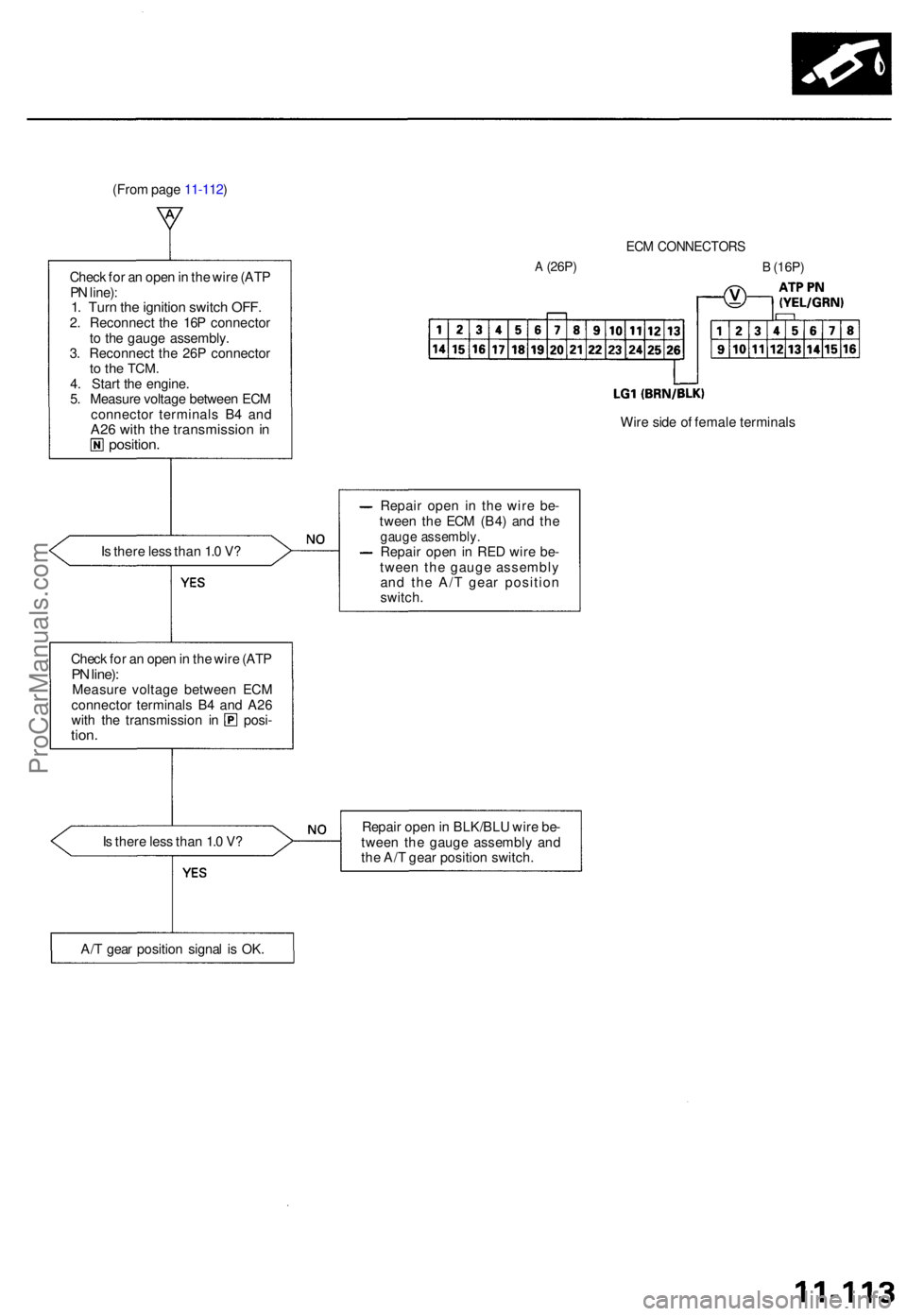
(From pag e 11-112 )
ECM CONNECTOR S
A (26P)
Wire sid e o f femal e terminal s
I s ther e les s tha n 1. 0 V ? Repai
r ope n i n th e wir e be -
twee n th e EC M (B4 ) an d th e
gaug e assembly .Repair ope n in RE D wir e be -
twee n th e gaug e assembl y
an d th e A/ T gea r positio n
switch.
Check fo r a n ope n in th e wir e (AT PPN line) :Measur e voltag e betwee n EC M
connecto r terminal s B 4 an d A2 6
with th e transmissio n i n posi -tion.
Is ther e les s tha n 1. 0 V ? Repai
r ope n in BLK/BL U wir e be -
twee n th e gaug e assembl y an d
th e A/ T gea r positio n switch .
A/ T gea r positio n signa l i s OK .
Chec
k fo r a n ope n in th e wir e (AT P
P N line) :
1. Tur n th e ignitio n switc h OFF .2. Reconnec t th e 16 P connecto r
t o th e gaug e assembly .
3 . Reconnec t th e 26 P connecto r
to th e TCM .4. Star t th e engine .
5 . Measur e voltag e betwee n EC M
connecto r terminal s B 4 an d
A26 wit h th e transmissio n inposition .
B (16P)
ProCarManuals.com
Page 892 of 1771
Idle Contro l Syste m
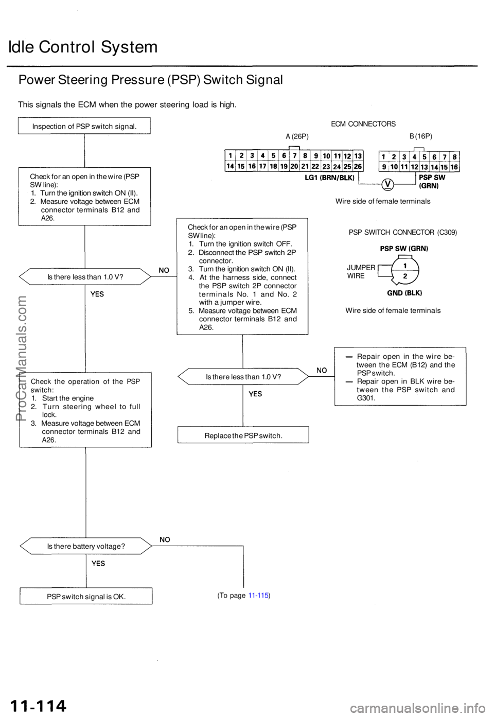
Power Steerin g Pressur e (PSP ) Switc h Signa l
This signal s th e EC M whe n th e powe r steerin g loa d is high .
Is ther e les s tha n 1. 0 V ?
Chec k th e operatio n o f th e PS Pswitch :
1 . Star t th e engin e
2 . Tur n steerin g whee l t o ful l
lock .3. Measur e voltag e betwee n EC M
connecto r terminal s B1 2 an d
A26 .
Is ther e batter y voltage ?
ECM CONNECTOR S
A (26P)B (16P)
Chec k fo r a n ope n in th e wir e (PS P
S W line) :
1 . Tur n th e ignitio n switc h OFF .
2. Disconnec t th e PS P switc h 2 Pconnector .3. Tur n th e ignitio n switc h O N (II) .
4 . A t th e harnes s side , connec t
th e PS P switc h 2 P connecto r
terminal s No . 1 an d No . 2
wit h a jumpe r wire .5. Measur e voltag e betwee n EC M
connecto r terminal s B1 2 an d
A26 .
Is ther e les s tha n 1. 0 V ? Repai
r ope n i n th e wir e be -
twee n th e EC M (B12 ) an d th e
PS P switch .
Repai r ope n in BL K wir e be -
twee n th e PS P switc h an d
G301 .
(To pag e 11-115 )PSP switc h signa l i s OK . Replac
e th e PS P switch . Wir
e sid e o f femal e terminal s
JUMPERWIRE
PSP SWITC H CONNECTO R (C309 )
Wire side of femal e terminal s
Chec
k fo r a n ope n in th e wir e (PS P
S W line) :1. Tur n th e ignitio n switc h O N (II) .2. Measur e voltag e betwee n EC M
connecto r terminal s B1 2 an d
A26 .
Inspectio n o f PS P switc h signal .
ProCarManuals.com
Page 893 of 1771
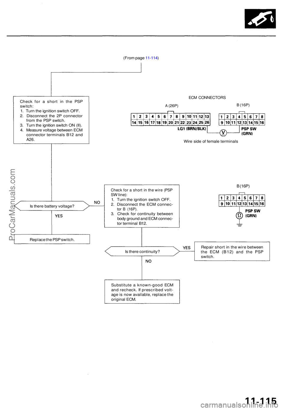
(From pag e 11-114 )
Chec k fo r a shor t i n th e PS P
switch :1. Tur n th e ignitio n switc h OFF .2. Disconnec t th e 2 P connecto r
fro m th e PS P switch .
3 . Tur n th e ignitio n switc h O N (II) .
4 . Measur e voltag e betwee n EC M
connecto r terminal s B1 2 an d
A26 .
ECM CONNECTOR S
A (26P)B (16P)
Wire sid e o f femal e terminal s
I s ther e batter y voltage ?
B (16P)
Is ther e continuity ? Repai
r shor t i n th e wir e betwee nthe EC M (B12 ) and th e PS Pswitch .
Substitut e a known-goo d EC M
an d recheck . I f prescribe d volt -
ag e is no w available , replac e th e
origina l ECM .
Replac
e th e PS P switch .
Check fo r a shor t i n th e wir e (PS PSW line) :
1 . Tur n th e ignitio n switc h OFF .
2 . Disconnec t th e EC M connec -
tor B (16P) .3. Chec k fo r continuit y betwee n
bod y groun d an d EC M connec -
to r termina l B12 .
ProCarManuals.com
Page 894 of 1771
Idle Contro l Syste m
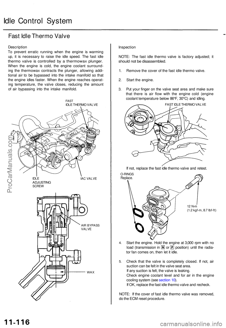
Fast Idl e Therm o Valv e
Descriptio n
T o preven t errati c runnin g whe n th e engin e i s warmin g
up , i t i s necessar y t o rais e th e idl e speed . Th e fas t idl e
therm o valv e i s controlle d b y a thermowa x plunger .
When th e engin e i s cold , th e engin e coolan t surround -
in g th e thermowa x contract s th e plunger , allowin g addi -
tiona l ai r t o b e bypasse d int o th e intak e manifol d s o tha t
th e engin e idle s faster . Whe n th e engin e reache s operat -
in g temperature , th e valv e closes , reducin g th e amoun t
o f ai r bypassin g int o th e intak e manifold .
FASTIDLE THERM O VALV E
IDLEADJUSTIN GSCREW
IAC VALV E
AIR BYPAS SVALVE
WAX
Inspectio n
NOTE : Th e fas t idl e therm o valv e i s factor y adjusted ; i t
shoul d no t b e disassembled .
1. Remov e th e cove r o f th e fas t idl e therm o valve .
2 . Star t th e engine .
3.Pu t you r finge r o n th e valv e sea t are a an d mak e sur e
tha t ther e i s ai r flo w wit h th e engin e col d (engin e
coolan t temperatur e belo w 86°F , 30°C ) an d idling .
FAST IDL E THERM O VALV E
If not , replac e th e fas t idl e therm o valv e an d retest .
O-RING SReplace .
12 N- m(1.2 kgf-m , 8. 7 Ibf-ft )
4.
5 .
Star t th e engine . Hol d th e engin e a t 3,00 0 rp m wit h n o
loa d (transmissio n in o r position ) unti l th e radia -
to r fa n come s on , the n le t i t idle .
Chec k tha t th e valv e i s completel y closed . I f not , ai r
suctio n ca n b e fel t i n th e valv e sea t area .
I f an y suctio n is felt , th e valv e is leaking .
Chec k engin e coolan t leve l an d fo r ai r i n th e engin e
coolin g syste m (se e sectio n 10 ).
I f OK , replac e th e fas t idl e therm o valv e an d recheck .
NOTE : I f th e cove r o f fas t idl e therm o valv e wa s removed ,
d o th e EC M rese t procedure .
ProCarManuals.com
Page 895 of 1771
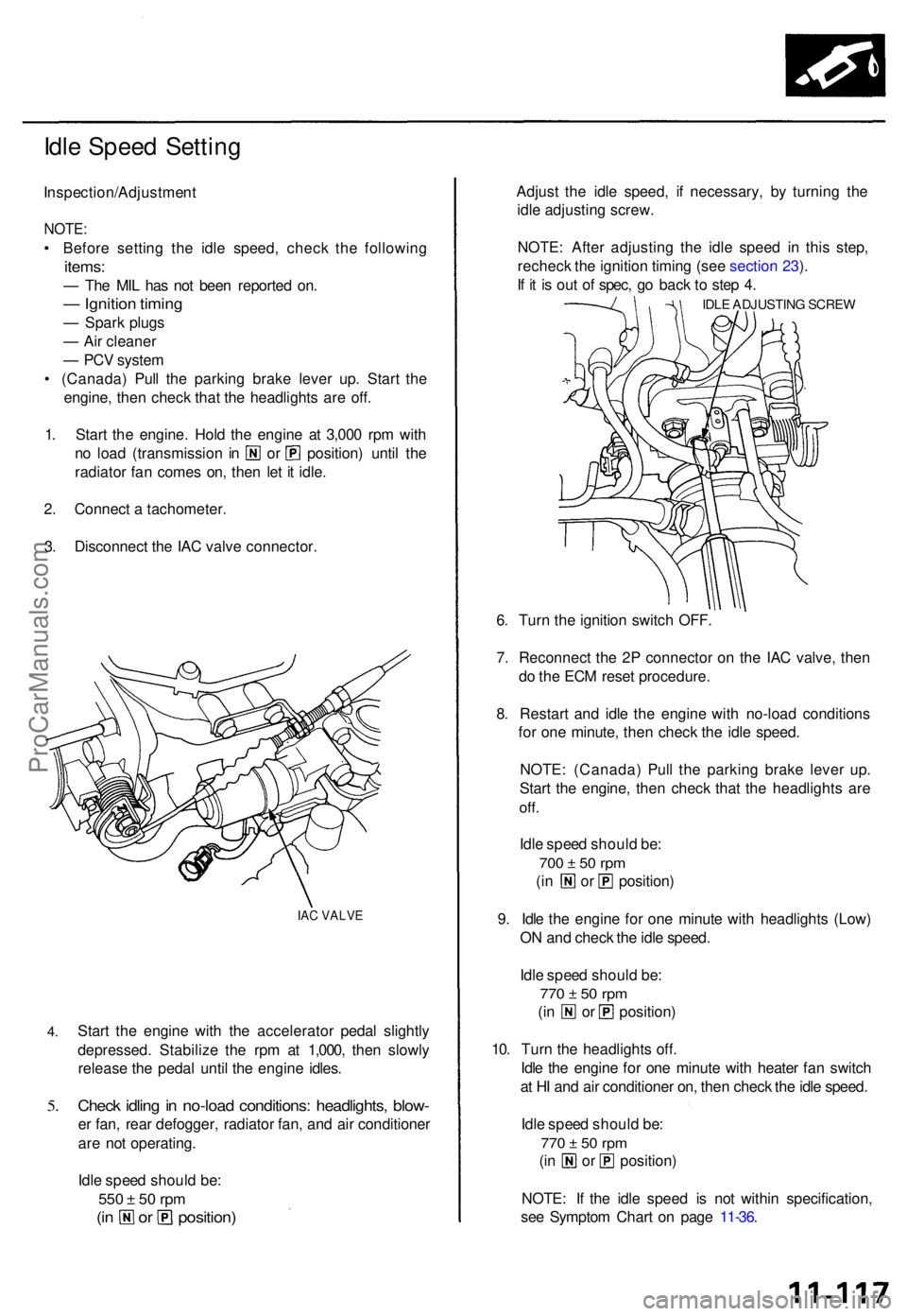
Idle Spee d Settin g
Inspection/Adjustmen t
NOTE:
• Befor e settin g th e idl e speed , chec k th e followin g
items:
— Th e MI L ha s no t bee n reporte d on .
— Ignitio n timin g
— Spar k plug s
— Ai r cleane r
— PC V syste m
• (Canada ) Pul l th e parkin g brak e leve r up . Star t th e
engine , the n chec k tha t th e headlight s ar e off .
1 . Star t th e engine . Hol d th e engine at 3,00 0 rp m wit h
no loa d (transmissio n i n o r position ) unti l th e
radiato r fa n come s on , the n le t i t idle .
2 . Connec t a tachometer .
3 . Disconnec t th e IA C valv e connector .
IAC VALV E
4.
5.
Star t th e engin e wit h th e accelerato r peda l slightl y
depressed . Stabiliz e th e rp m a t 1,000 , the n slowl y
releas e th e peda l unti l th e engin e idles .
Check idlin g in no-loa d conditions : headlights , blow -
er fan , rea r defogger , radiato r fan , an d ai r conditione r
ar e no t operating .
Idl e spee d shoul d be :
550 ± 5 0 rp m
(in o r position )
Adjust th e idl e speed , i f necessary, by turnin g th e
idl e adjustin g screw .
NOTE : Afte r adjustin g th e idl e spee d i n thi s step ,
rechec k th e ignitio n timin g (se e sectio n 23 ).
I f i t i s ou t o f spec , g o bac k t o ste p 4 .
IDL E ADJUSTIN G SCRE W
6. Tur n th e ignitio n switc h OFF .
7 . Reconnec t th e 2 P connecto r o n th e IA C valve , the n
d o th e EC M rese t procedure .
8 . Restar t an d idl e th e engine with no-loa d condition s
fo r on e minute , the n chec k th e idl e speed .
NOTE : (Canada ) Pul l th e parkin g brak e leve r up .
Star t th e engine , the n chec k tha t th e headlight s ar e
off.
Idle spee d shoul d be :
700 ± 5 0 rp m
(in o r position )
9 . Idl e th e engin e fo r on e minut e wit h headlight s (Low )
O N an d chec k th e idl e speed .
Idl e spee d shoul d be :
770 ± 5 0 rp m
(in o r position )
10 . Tur n th e headlight s off .
Idl e th e engin e fo r on e minut e wit h heate r fa n switc h
a t H I an d ai r conditione r on , the n chec k th e idl e speed .
Idl e spee d shoul d be :
770 ± 5 0 rp m
(in o r position )
NOTE : I f th e idl e spee d i s no t withi n specification ,
se e Sympto m Char t o n pag e 11-36 .
ProCarManuals.com
Page 896 of 1771
Fuel Supply System
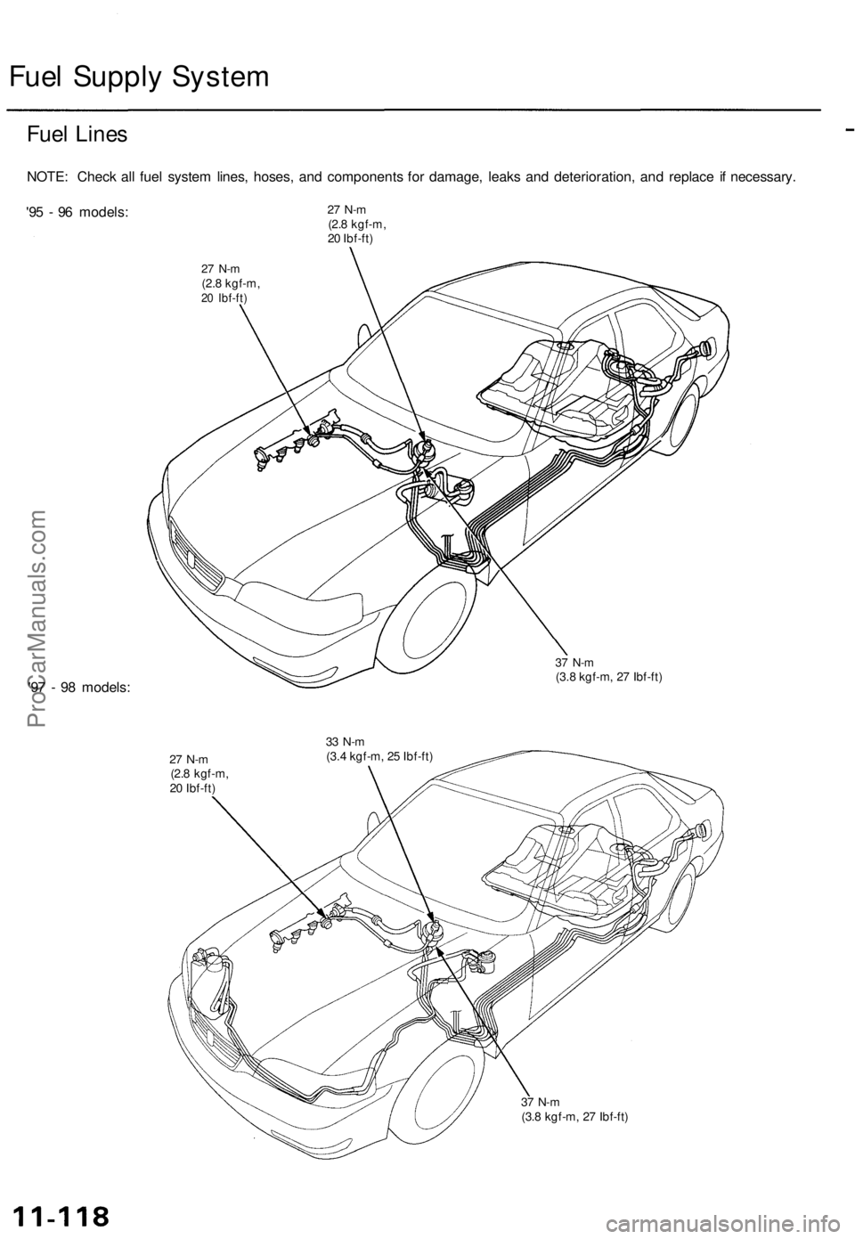
Fuel Lines
NOTE: Check all fuel system lines, hoses, and components for damage, leaks and deterioration, and replace if necessary.
'95 - 96 models:
27 N-m
(2.8 kgf-m,
20 Ibf-ft)
27 N-m
(2.8 kgf-m,
20 Ibf-ft)
'97 - 98 models:
37 N-m
(3.8 kgf-m, 27 Ibf-ft)
27 N-m
(2.8 kgf-m,
20 Ibf-ft)
33 N-m
(3.4 kgf-m, 25 Ibf-ft)
37 N-m
(3.8 kgf-m, 27 Ibf-ft)ProCarManuals.com
Page 897 of 1771
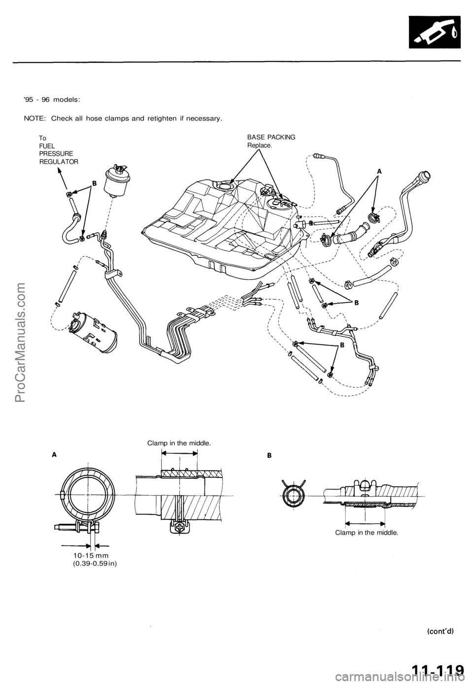
'95 - 96 models:
NOTE: Check all hose clamps and retighten if necessary.
To
FUEL
PRESSURE
REGULATOR
BASE PACKING
Replace.
10-15
mm
(0.39-0.59 in)
Clamp in the middle.
Clamp in the middle.ProCarManuals.com
Page 898 of 1771
Fuel Supply System
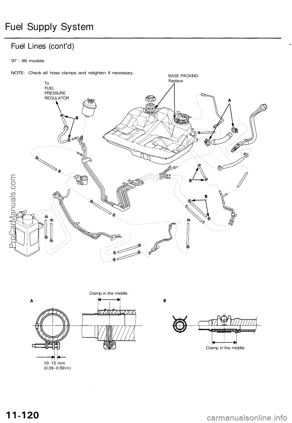
Fuel Lines (cont'd)
'97 - 98 models:
NOTE: Check all hose clamps and retighten if necessary.
To
FUEL
PRESSURE
REGULATOR
BASE PACKING
Replace.
10- 15 mm
(0.39
-
0.59
in)
Clamp in the middle.
Clamp in the middle.ProCarManuals.com
Page 899 of 1771
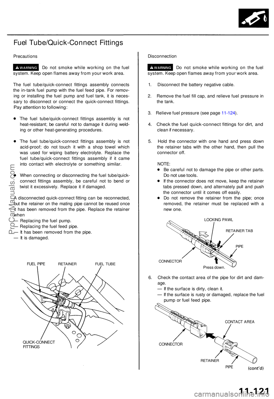
Fuel Tube/Quick-Connec t Fitting s
Precaution s
Do no t smok e whil e workin g o n th e fue l
system . Kee p ope n flame s awa y fro m you r wor k area .
Th e fue l tube/quick-connec t fitting s assembl y connect s
th e in-tan k fue l pum p wit h th e fue l fee d pipe . Fo r remov -
in g o r installin g th e fue l pum p an d fue l tank , i t i s neces -
sar y t o disconnec t o r connec t th e quick-connec t fittings .
Pay attentio n to following :
The fue l tube/quick-connec t fitting s assembl y i s no t
heat-resistant ; b e carefu l no t t o damag e it durin g weld -
in g o r othe r heat-generatin g procedures .
Th e fue l tube/quick-connec t fitting s assembl y i s no t
acid-proof ; d o no t touc h i t wit h a sho p towe l whic h
wa s use d fo r wipin g batter y electrolyte . Replac e th e
fue l tube/quick-connec t fitting s assembl y i f i t cam e
int o contac t wit h electrolyt e o r somethin g similar .
Whe n connectin g o r disconnectin g th e fue l tube/quick -
connec t fitting s assembly , b e carefu l no t t o ben d o r
twis t i t excessively . Replac e i t i f damaged .
A disconnecte d quick-connec t fittin g ca n b e reconnected ,
bu t th e retaine r o n th e matin g pip e canno t b e reuse d onc e
i t ha s bee n remove d fro m th e pipe . Replac e th e retaine r
whe n
— Replacin g th e fue l pump .
— Replacin g th e fue l fee d pipe .
— It ha s bee n remove d fro m th e pipe .
— It i s damaged .
FUEL PIP ERETAINE RFUEL TUB E
QUICK-CONNEC TFITTINGS
Disconnectio n
Do no t smok e whil e workin g o n th e fue l
system . Kee p ope n flame s awa y fro m you r wor k area .
1 . Disconnec t th e batter y negativ e cable .
2 . Remov e th e fue l fil l cap , an d reliev e fue l pressur e in
th e tank .
3 . Reliev e fue l pressur e (se e pag e 11-124 ).
4 . Chec k th e fue l quick-connec t fitting s fo r dirt , an d
clea n if necessary .
5 . Hol d th e connecto r wit h on e han d an d pres s dow n
th e retaine r tab s wit h th e othe r hand , the n pul l th e
connecto r off .
NOTE :
Be carefu l no t t o damag e th e pip e o r othe r parts .
Do no t us e tools .
If th e connecto r doe s no t move , kee p th e retaine r
tab s presse d down , an d alternatel y pul l an d pus h
th e connecto r unti l i t come s of f easily .
D o no t remov e th e retaine r fro m th e pipe ; onc e
removed , th e retaine r mus t b e replace d wit h a
ne w one .
LOCKIN G PAW L
RETAINE R TA B
PIPE
CONNECTO R
Press down .
6. Chec k th e contac t are a o f th e pip e fo r dir t an d dam -
age.
— If th e surfac e is dirty , clea n it .
— If th e surface is rust y o r damaged , replac e th e fue l
pum p o r fue l fee d pipe .
CONTAC T ARE A
CONNECTO R
RETAINER
PIPE
ProCarManuals.com
Page 900 of 1771
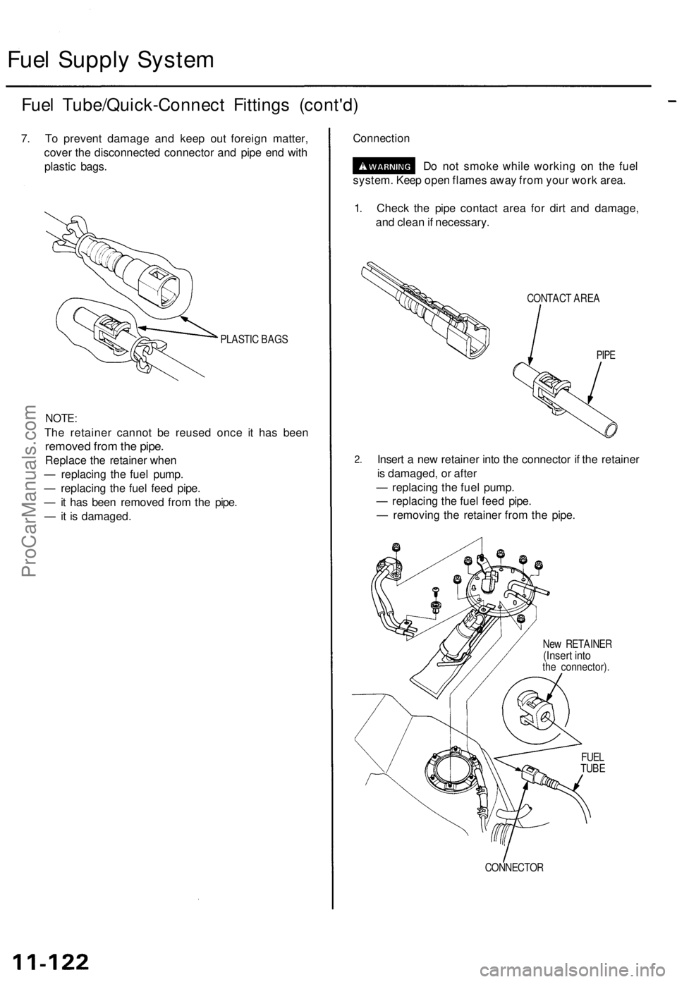
Fuel Supply System
Fuel Tube/Quick-Connect Fittings (cont'd)
7. To prevent damage and keep out foreign matter,
cover the disconnected connector and pipe end with
plastic bags.
PLASTIC BAGS
NOTE:
The retainer cannot be reused once it has been
removed from the pipe.
Replace the retainer when
— replacing the fuel pump.
— replacing the fuel feed pipe.
— it has been removed from the pipe.
— it is damaged.
Connection
Do not smoke while working on the fuel
system. Keep open flames away from your work area.
1. Check the pipe contact area for dirt and damage,
and clean if necessary.
CONTACT AREA
PIPE
2.
Insert a new retainer into the connector if the retainer
is damaged, or after
— replacing the fuel pump.
— replacing the fuel feed pipe.
— removing the retainer from the pipe.
New RETAINER
(Insert into
the connector).
CONNECTOR
FUEL
TUBEProCarManuals.com