ASTON MARTIN V8 VANTAGE 2010 Workshop Manual
Manufacturer: ASTON MARTIN, Model Year: 2010, Model line: V8 VANTAGE, Model: ASTON MARTIN V8 VANTAGE 2010Pages: 947, PDF Size: 43.21 MB
Page 841 of 947

Electronics Training Programme
36
Page 842 of 947

Page 843 of 947

Electronics Training Programme
38
Page 844 of 947

Page 845 of 947

Aston Martin On Board Diagnostics (OBD) Summary Documentation
Page 846 of 947

Contents
Item No. of Pages
1. EOBD Monitors Summary 43
Dated 1st May 2009
2. 09MY V8 Vantage EOBD Documentation
a. D ata Tables 13
b. Function Tables 1
c. Notes 1
d. ASM Transmission Data Tables 6
3. V12 Family EOBD Documentation
V12 Vantage, 09MY DBS & 09MY DB9 EOBD Documentation
e. Data Tables 16
f. Function Tables 2
g. Notes 2
h. 09MY DB9 & DBS Automatic Transmission Summary 4
Note: The V12 EOBD engine family is certified as a single submission.
The calibration content and therefore th e data is identical for each model
with the V12 engine; V12 Vantage, DBS and DB9.
The Automatic Transmission summary is included but does not apply to
the V12 Vantage.
Page 847 of 947

AML EOBD System Operation Summary
Rory O’Curry Aston Martin Lagonda CONFIDENTIAL 1 May 2009
AML EOBD System Operation
Summary
[email protected] AML EOBD Monitors 07 ROC.doc Page 1 of 43
Page 848 of 947

AML EOBD System Operation Summary
Rory O’Curry Aston Martin Lagonda CONFIDENTIAL 1 May 2009
[email protected] AML EOBD Monitors 07 ROC.doc Page 2 of 43
AML EOBD System Operation
Summary for Gasoline Engines.
Contents
Introduction ........................................................................................................................................................................................3
Catalyst Efficiency Monitor ...............................................................................................................................................................4
Misfire Monitor..................................................................................................................................................................................6
Fuel System Monitor ..........................................................................................................................................................................9
HO2S Monitor............................................................................................................................... ...................................................10
Differential Pressure Feedback EGR System Monitor.....................................................................................................................13
Electronic Throttle Monitor............................................................................................................................... ...............................16
Dual MAF Diagnostic............................................................................................................................... .......................................18
SAIR Monitor............................................................................................................................... ....................................................22
VCT Monitor............................................................................................................................... .....................................................25
Comprehensive Component Monitor - Engine............................................................................................................................... ..27
Comprehensive Component Monitor - Manual Transmission..........................................................................................................30
Comprehensive Component Monitor - Automatic Transmission .....................................................................................................31
6HP26 Automatic Transmission............................................................................................................................... ........................34
Auto Shift Manual (ASM) Transmission............................................................................................................................... ...........34
Inspection Maintenance Readiness Code............................................................................................................................... ..........35
Tamper Protection............................................................................................................................... .............................................35
Serial Data Link Connector............................................................................................................................... ...............................35
Serial Data Link Communication Protocol............................................................................................................................... ........35
Serial Data Link MIL Illumination............................................................................................................................... ....................36
Glossary of Terms............................................................................................................................... .............................................37
MIL Code List............................................................................................................................... ...................................................39
MIL Symbol............................................................................................................................... ......................................................43
Page 849 of 947

AML EOBD System Operation Summary
Rory O’Curry Aston Martin Lagonda CONFIDENTIAL 1 May 2009
[email protected] AML EOBD Monitors 07 ROC.doc Page 3 of 43
Introduction
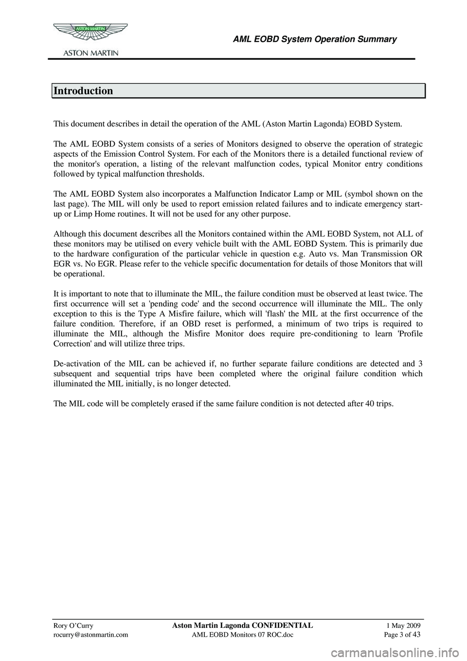
This document describes in detail the operation of the AML (Aston Martin Lagonda) EOBD System.
The AML EOBD System consists of a series of Mon itors designed to observe the operation of strategic
aspects of the Emission Control System. For each of the Monitors there is a detailed functional review of
the monitor's operation, a listing of the relevant malfunction codes, typical Monitor entry conditions
followed by typical malfunction thresholds.
The AML EOBD System also incorporates a Malfunction Indicator Lamp or MIL (symbol shown on the
last page). The MIL will only be used to report emi ssion related failures and to indicate emergency start-
up or Limp Home routines. It will not be used for any other purpose.
Although this document describes all the Monitors cont ained within the AML EOBD System, not ALL of
these monitors may be utilised on every vehicle built w ith the AML EOBD System. This is primarily due
to the hardware configuration of the particular vehicle in question e.g. Auto vs. Man Transmission OR
EGR vs. No EGR. Please refer to the vehicle specific documentation for details of those Monitors that will
be operational.
It is important to note that to illuminate the MIL, th e failure condition must be observed at least twice. The
first occurrence will set a 'pending code' and the second occurrence will illuminate the MIL. The only
exception to this is the Type A Misfire failure, whic h will 'flash' the MIL at the first occurrence of the
failure condition. Therefore, if an OBD reset is performed, a minimum of two trips is required to
illuminate the MIL, although the Misfire Monitor does require pre-conditioning to learn 'Profile
Correction' and will utilize three trips.
De-activation of the MIL can be achieved if, no furt her separate failure conditions are detected and 3
subsequent and sequential trips have been comp leted where the original failure condition which
illuminated the MIL initially, is no longer detected.
The MIL code will be completely erased if the same failure condition is not detected after 40 trips.
Page 850 of 947

AML EOBD System Operation Summary
Rory O’Curry Aston Martin Lagonda CONFIDENTIAL 1 May 2009
[email protected] AML EOBD Monitors 07 ROC.doc Page 4 of 43
Catalyst Efficiency Monitor
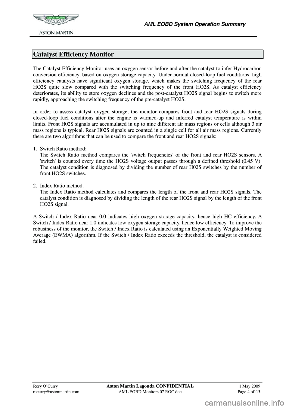
The Catalyst Efficiency Monitor uses an oxygen sensor before and after the catalyst to infer Hydrocarbon
conversion efficiency, based on oxygen storage capac ity. Under normal closed-loop fuel conditions, high
efficiency catalysts have significant oxygen storage, which makes the switching frequency of the rear
HO2S quite slow compared with the switching freque ncy of the front HO2S. As catalyst efficiency
deteriorates, its ability to store oxygen declines and the post-catalyst HO2S signal begins to switch more
rapidly, approaching the switching frequency of the pre-catalyst HO2S.
In order to assess catalyst oxygen storage, the monitor compares front and rear HO2S signals during
closed-loop fuel conditions after the engine is warm ed-up and inferred catalyst temperature is within
limits. Front H02S signals are accumulated in up to ni ne different air mass regions or cells although 3 air
mass regions is typical. Rear H02S signals are counted in a single cell for all air mass regions. Currently
there are two algorithms that can be used to compare the front and rear HO2S signals:
1. Switch Ratio method;
The Switch Ratio method compares the 'switch frequencies' of the front and rear HO2S sensors. A
'switch' is counted every time the HO2S voltage output passes through a defined threshold (0.45 V).
The catalyst condition is diagnosed by dividing the number of rear H02S switches by the number of
front HO2S switches.
2. Index Ratio method.
The Index Ratio method calculates and compares the length of the front and rear HO2S signals. The
catalyst condition is diagnosed by dividing the length of the rear HO2S signal by the length of the front
HO2S signal.
A Switch / Index Ratio near 0.0 indicates high oxygen storage capacity, hence high HC efficiency. A
Switch / Index Ratio near 1.0 indicates low oxygen storage capacity, hence low efficiency. To improve the
robustness of the monitor, the Switch / Index Ratio is calculated using an Exponentially Weighted Moving
Average (EWMA) algorithm. If the Switch / Index Ratio exceeds the threshold, the catalyst is considered
failed.