AUDI A6 2000 C5 / 2.G Changing Clutch 5Speed Manual Gearbox
Manufacturer: AUDI, Model Year: 2000,
Model line: A6,
Model: AUDI A6 2000 C5 / 2.G
Pages: 71, PDF Size: 1.82 MB
AUDI A6 2000 C5 / 2.G Changing Clutch 5Speed Manual Gearbox
A6 2000 C5 / 2.G
AUDI
AUDI
https://www.carmanualsonline.info/img/6/841/w960_841-0.png
AUDI A6 2000 C5 / 2.G Changing Clutch 5Speed Manual Gearbox
Trending: oil level, oil, ECU, clock, relay, wheel bolts, engine
Page 61 of 71
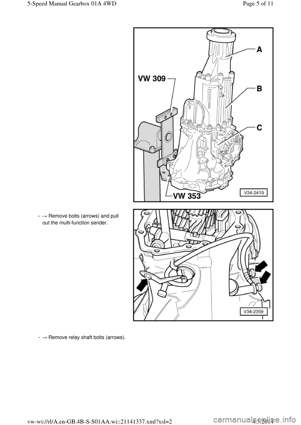
‒ → Remove bolts (arrows) and pull
out the multi-function sender. ‒ → Remove relay shaft bolts (arrows). Page 5 of 115-Speed Manual Gearbox 01A 4WD4.3.2014vw-wi://rl/A.en-GB.4B-S-S01AA.wi::21141337.xml?xsl=2
Page 62 of 71
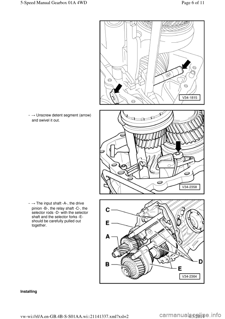
‒ → Unscrew detent segment (arrow)
and swivel it out. ‒ → The input shaft -A-, the drive
pinion -B-, the relay shaft -C-, the
selector rods -D- with the selector
shaft and the selector forks -E-
should be carefully pulled out
together. Installing Page 6 of 115-Speed Manual Gearbox 01A 4WD4.3.2014vw-wi://rl/A.en-GB.4B-S-S01AA.wi::21141337.xml?xsl=2
Page 63 of 71
Note: If the input shaft ball bearing, the input shaft or the gearbox housing are renewed, it is
necessary to re-determine the thickness of
the circlips for the input shaft =>Page 35-23, adjusting input shaft.
‒ → Swing the gearbox housing into
the position shown.
‒ The components listed below can
then be fitted more easily. ‒ → Put the input shaft -A-, the drive
pinion -B-, the relay shaft -C-, the
selector rods -D- with the selector
shaft and the selector forks -E-
together.
‒ Install these components together
into the gearbox housing.
Note:
Relay shaft -C- and the selector shaft can
also be retrofitted =>next page, Fig. N34-
0585 and Fig. V34-2120. ‒ → Turn gearbox housing and
engage 3rd gear (direction of arrow). Page 7 of 115-Speed Manual Gearbox 01A 4WD4.3.2014vw-wi://rl/A.en-GB.4B-S-S01AA.wi::21141337.xml?xsl=2
Page 64 of 71
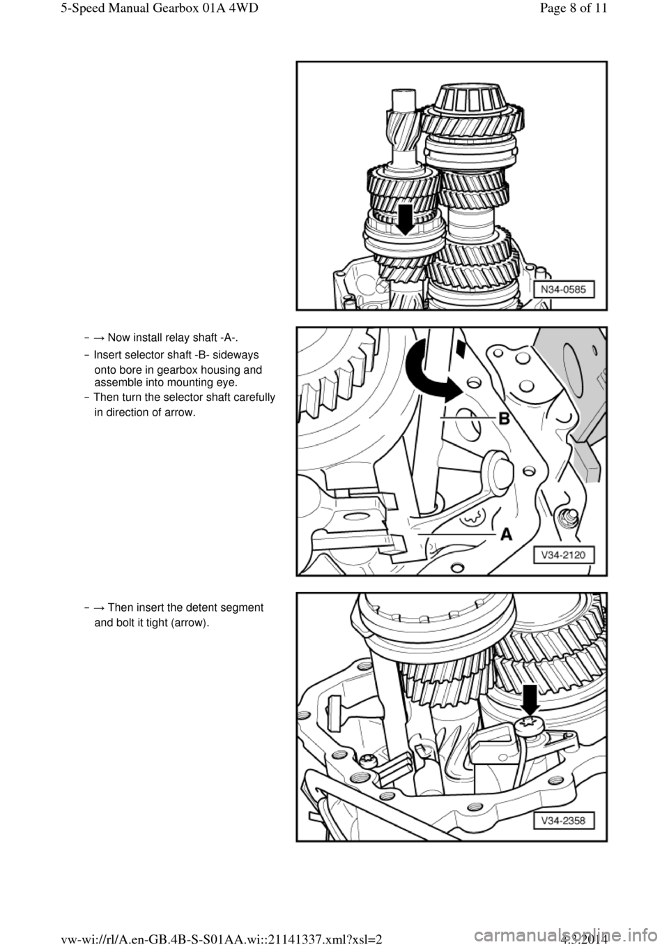
‒ → Now install relay shaft -A-.
‒ Insert selector shaft -B- sideways
onto bore in gearbox housing and
assemble into mounting eye.
‒ Then turn the selector shaft carefully
in direction of arrow. ‒ → Then insert the detent segment
and bolt it tight (arrow). Page 8 of 115-Speed Manual Gearbox 01A 4WD4.3.2014vw-wi://rl/A.en-GB.4B-S-S01AA.wi::21141337.xml?xsl=2
Page 65 of 71
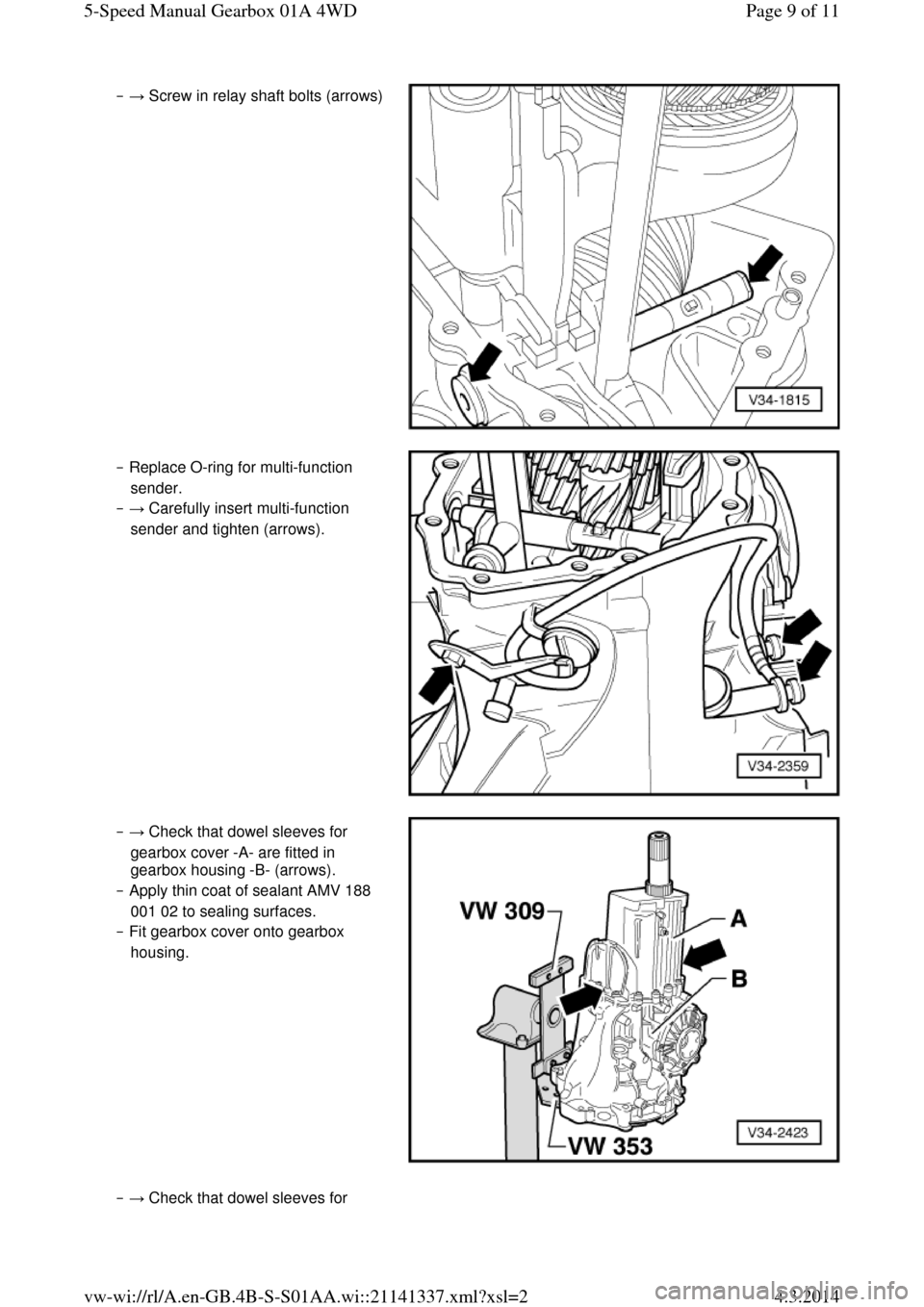
‒ → Screw in relay shaft bolts (arrows) ‒ Replace O-ring for multi-function
sender.
‒ → Carefully insert multi-function
sender and tighten (arrows). ‒ → Check that dowel sleeves for
gearbox cover -A- are fitted in
gearbox housing -B- (arrows).
‒ Apply thin coat of sealant AMV 188
001 02 to sealing surfaces.
‒ Fit gearbox cover onto gearbox
housing. ‒ → Check that dowel sleeves for Page 9 of 115-Speed Manual Gearbox 01A 4WD4.3.2014vw-wi://rl/A.en-GB.4B-S-S01AA.wi::21141337.xml?xsl=2
Page 66 of 71
cover -A- are fitted in gearbox cover -
B- (arrows).
‒ Fit spring -C-.
‒ Apply thin coat of sealant AMV 188
001 02 to sealing surfaces.
‒ Fit cover with Torsen differential -A-
on gearbox cover -B-. ‒ → Fit rear input shaft ball bearing
circlip (arrow).
‒ Push the ball bearing onto the input
shaft.
‒ Installation position: closed
side of ball cage faces
towards gearbox housing ‒ → Press in ball bearing:
‒ Push thrust pad -A- of pressing-in
tool onto input shaft.
‒ Position pressing-in tool behind
splines for clutch plate.
‒ Screw in the bolts -B- until they make contact.
‒ The bolts bear against the
indentations in thrust pad -A-. ‒ Press in ball bearing onto its seat by
alternately tightening the bolts (1/2
turn at a time). ‒ → Now fit the front circlip -D- for the Page 10 of 115-Speed Manual Gearbox 01A 4WD4.3.2014vw-wi://rl/A.en-GB.4B-S-S01AA.wi::21141337.xml?xsl=2
Page 67 of 71
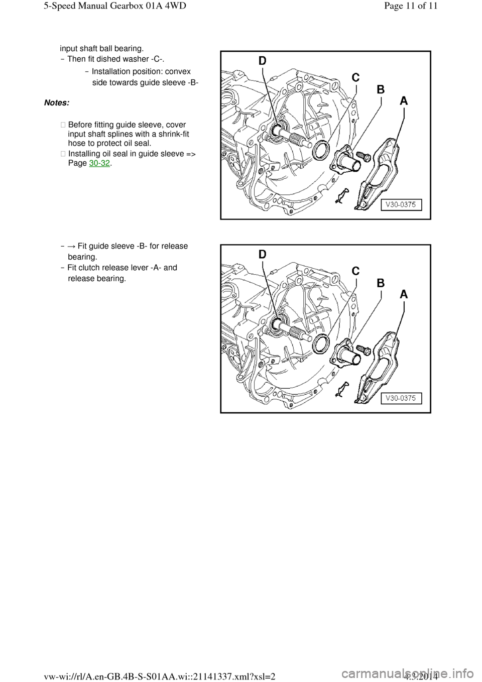
input shaft ball bearing.
‒ Then fit dished washer -C-.
‒ Installation position: convex
side towards guide sleeve -B- Notes:
◆ Before fitting guide sleeve, cover
input shaft splines with a shrink-fit
hose to protect oil seal.
◆ Installing oil seal in guide sleeve =>
Page 30-32. ‒ → Fit guide sleeve -B- for release
bearing.
‒ Fit clutch release lever -A- and
release bearing. Page 11 of 115-Speed Manual Gearbox 01A 4WD4.3.2014vw-wi://rl/A.en-GB.4B-S-S01AA.wi::21141337.xml?xsl=2
Page 68 of 71
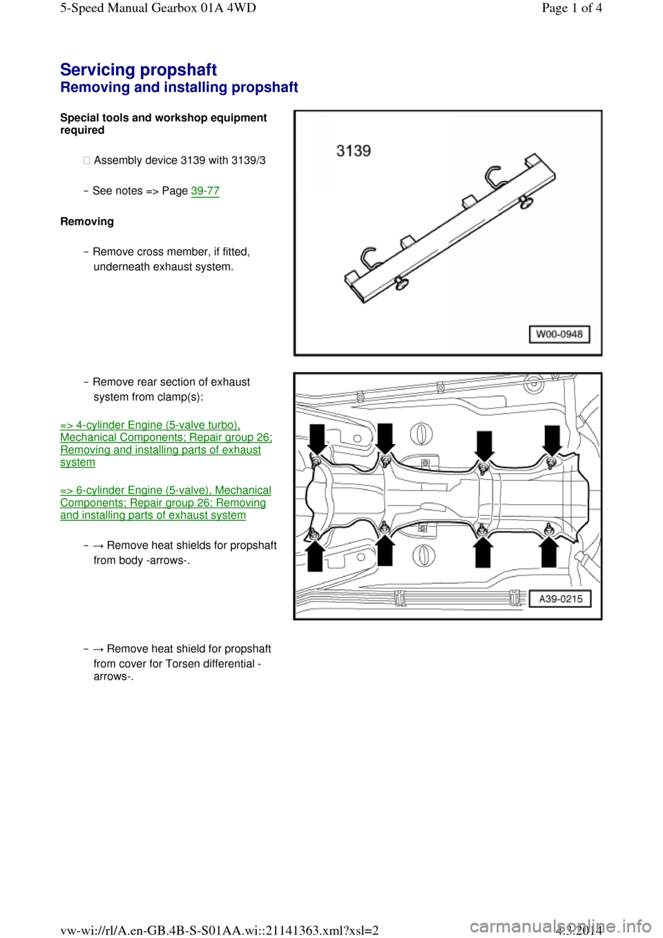
Servicing propshaft Removing and installing propshaft Special tools and workshop equipment required
◆ Assembly device 3139 with 3139/3
‒ See notes => Page 39-77
Removing
‒ Remove cross member, if fitted,
underneath exhaust system. ‒ Remove rear section of exhaust
system from clamp(s):
=> 4-cylinder Engine (5-valve turbo), Mechanical Components; Repair group 26; Removing and installing parts of exhaust system
=> 6-cylinder Engine (5-valve), Mechanical Components; Repair group 26; Removing and installing parts of exhaust system
‒ → Remove heat shields for propshaft from body -arrows-. ‒ → Remove heat shield for propshaft
from cover for Torsen differential -
arrows-. Page 1 of 45-Speed Manual Gearbox 01A 4WD4.3.2014vw-wi://rl/A.en-GB.4B-S-S01AA.wi::21141363.xml?xsl=2
Page 69 of 71
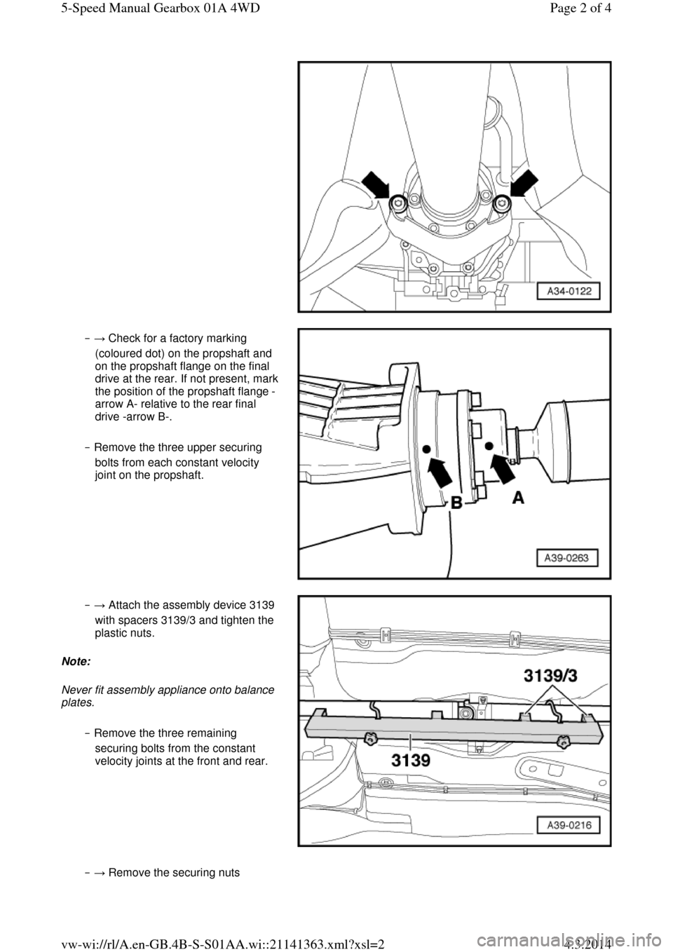
‒ → Check for a factory marking
(coloured dot) on the propshaft and
on the propshaft flange on the final drive at the rear. If not present, mark the position of the propshaft flange -
arrow A- relative to the rear final
drive -arrow B-.
‒ Remove the three upper securing
bolts from each constant velocity
joint on the propshaft. ‒ → Attach the assembly device 3139
with spacers 3139/3 and tighten the
plastic nuts.
Note:
Never fit assembly appliance onto balance plates.
‒ Remove the three remaining
securing bolts from the constant
velocity joints at the front and rear. ‒ → Remove the securing nuts Page 2 of 45-Speed Manual Gearbox 01A 4WD4.3.2014vw-wi://rl/A.en-GB.4B-S-S01AA.wi::21141363.xml?xsl=2
Page 70 of 71
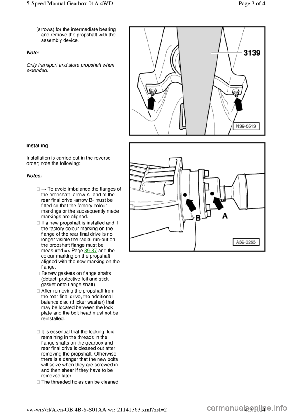
(arrows) for the intermediate bearing
and remove the propshaft with the
assembly device.
Note:
Only transport and store propshaft when
extended. Installing Installation is carried out in the reverse
order; note the following:
Notes:
◆ → To avoid imbalance the flanges of the propshaft -arrow A- and of the
rear final drive -arrow B- must be
fitted so that the factory colour
markings or the subsequently made
markings are aligned.
◆ If a new propshaft is installed and if
the factory colour marking on the
flange of the rear final drive is no
longer visible the radial run-out on
the propshaft flange must be
measured => Page 39-87 and the
colour marking on the propshaft
aligned with the new marking on the
flange.
◆ Renew gaskets on flange shafts
(detach protective foil and stick
gasket onto flange shaft).
◆ After removing the propshaft from
the rear final drive, the additional
balance disc (thicker washer) that
may be located between the lock
plate and the bolt head must not be
reinstalled.
◆ It is essential that the locking fluid
remaining in the threads in the
flange shafts on the gearbox and
rear final drive is cleaned out after
removing the propshaft. Otherwise
there is a danger that the new bolts
will seize when they are screwed in
and then shear if they have to be
removed later.
◆ The threaded holes can be cleaned Page 3 of 45-Speed Manual Gearbox 01A 4WD4.3.2014vw-wi://rl/A.en-GB.4B-S-S01AA.wi::21141363.xml?xsl=2
Trending: brake light, navigation, lock, fuel, check engine light, light, length
