AUDI R8 SPYDER 2011 Workshop Manual
Manufacturer: AUDI, Model Year: 2011, Model line: R8 SPYDER, Model: AUDI R8 SPYDER 2011Pages: 244, PDF Size: 59.74 MB
Page 51 of 244
The rear window can be extended comp lete ly
for cleaning. This is ca lled the cleaning posi
tion.
E xte nding the re ar w indow into the wind
defl ector po siti on
~ Pull and hold the rear window switch
9 fig. 47.
~ Release the switch once the rear window has
reached the wind deflector position.
Exte nd ing th e rear w indow into th e
cleaning po sition
~ Pull and hold the rear window switch
9 fig . 47.
~ Release the switch once the rear window has
reached the wind deflector position .
~ Pull and hold the rear window switch again .
~ Pull and hold the convertible top switch
within one second
9 page 46, fig . 43.
R etra cting the re ar w indow
~ Press and hold the rear window sw itch until
the window has been retracted .
Ret racting the re ar wi ndow using the one
touch funct ion
~ Press the rear window switch briefly . There
is no need to hold the switch.
The rear w indow can on ly be operated when
t he ignition is switched on.
The rear window can also be extended or re
tracted when the convertib le top is closed.
.&_ WARNING
- Do not use the rear window to secure car
go or other objects. This could result in
injury .
- Always pay attention and be careful
when extending or retracting the rear
window . It could cause injury by p inch
ing .
@ Tips
-Keeping all of the w indows raised pro
v ides the best wind protection.
Con vertible top 49
- The veh icle must be stationary to br ing
the rear window into the cleaning posi
tion . The rear window will retract once
you begin dr iv ing.
Convertible top
emergency operation
General information
The convertible top can be closed by hand if
there is a malfunction .
First check if overload pro tection is active
~ page 47. If this is the case, the conve rtible
top w ill operate again after a short de lay . O th
erwise the fo llowing steps must be completed
before closing the convertib le top:
~ Ac tiva te the pa rking brake.
~ Open the side w indows, if necessary.
~ Remove the key from the ignition.
Emergency loc king is no t intended for long
te rm use o r long drives . The convertib le top
will not be completely waterproof after using
the emergency locking proced ure because the
seals wi ll not be seated correctly. Only close
the convertible top manually in an emergency .
Please see an au thor ized Audi R8 dea ler to
have the cause of the malfunction corrected .
.&_ WARNING
-The ignition must be sw itched off during
the entire closing p rocedure.
- When positioning the convertible top,
avoid contact with the supports or other
mov ing parts. Othe rwise you could p inch
your hands.
- Never d rive when the convert ible top is
not locked cor re ctly. The wind from d riv
ing could cause the convertible top to
open . This can resu lt in injuries and dam
age to the vehicle.
@ Tips
Have a second person assist whe n closing
the convert ible top. Opening the storage
bay lid and posi tioning the conve rtible top
is easier when a seco nd person is assisting.
Page 52 of 244
50 Convertible top
Step 1: Retract the rear window
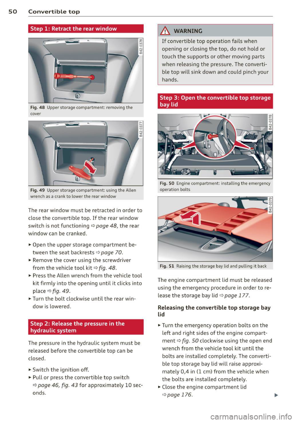
Fig. 48 Upper storage compartme nt: re mov ing the
cover
F ig. 49 Upper sto rage compartment: using the Allen
wrench as a crank to lower the rear win dow
M 0 N ... a,
... ... M 0
The rear window must be retracted in order to
close the convertible top. If the rear window
switch is not functioning ¢
page 48, the rear
window can be cranked .
.. Open the upper storage compartment be
tween the seat backrests ¢
page 70 .
.. Remove the cover using the screwdriver
from the vehicle tool kit¢
fig. 48.
• Press the Allen wrench from the veh icle tool
kit firmly into the opening until it cl icks into
place ¢
fig. 49.
> Turn the bolt clockw ise u ntil the rear win
dow is lowered .
Step 2: Release the pressure in the
hydraulic system
The pressure in the hydraulic system must be
re leased before the convertible top can be
closed.
.. Switch the ignition off .
.. Pull or press the convertible top switch
¢
page 46, fig. 43 for approximately 10 sec
onds.
A WARNING
-
If convertib le top operation fails when
opening or closing the top, do not hold or
touch the supports or other moving parts
when releasing the pressure. The converti
ble top will sink down and could pinch your
hands.
Step 3 : Open the convertible top storage
bay lid
Fig. SO E ng ine compartme nt: install ing the eme rgency
ope rat io n bolts
Fig. 51 Raising the sto rage bay lid and pulling it back
The engine compartment lid must be released
using the emergency procedure in order to re
l ease the storage bay lid ¢
page 177.
Releasing the convertible top storage bay
lid
.. Turn the emergency operat ion bolts on the
left and right sides of the engine compart
ment¢
fig. SO clockw ise using the open end
wrench from the vehicle too l kit until the
bolts are installed completely . The co nverti
ble top sto rage bay lid will raise app rox i
mate ly 0,4 in (1 cm) from the vehicle when
t he bolts are install ed comp letely .
• Close the engine compartment lid
r=;, page 176.
Page 53 of 244
Opening the con vertibl e top stor age bay
lid
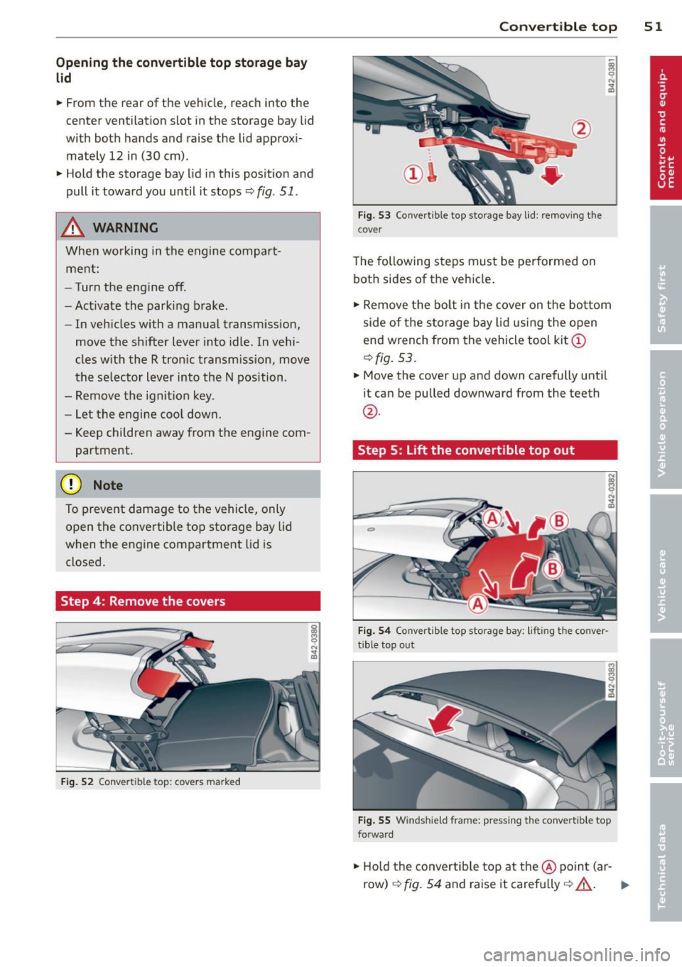
• From the rear of the vehicle, reach into the
center ventilation slot in the storage bay lid
with both hands and raise the lid approxi
mately 12 in (30 cm).
"' Hold the storage bay lid in this pos ition and
pull it toward you until it stops ¢
fig. 51.
& WARNING
When wo rking in the engine compart
ment:
- Turn the engine off .
- Act ivate the parking brake.
-
- In veh icles with a manual transm ission,
move the sh ifter lever into idle . In vehi-
cles w ith the R tronic transmission, move
the se lector lever into the N position.
- Remove the ignit ion key.
- Let the engine coo l down.
- Keep children away from the engine com-
partment .
(D Note
To prevent damage to the vehicle, only
open the convertible top storage bay lid
when the engine compartment lid is
closed.
Step 4: Remove the covers
F ig. 52 Convertib le to p: covers marked
Convert ible top 5 1
Fig. 53 Convert ible top storage bay lid: remov ing the
cover
The following steps must be performed on
both sides of the vehicle .
"' Remove the bolt in the cover on the bo ttom
side of the s torage bay lid using the o pen
end wrench from the vehicle too l kit @
¢fig. 53.
"'Move the cover up and down carefully until
it can be pulled downward from the teeth
@ .
Step 5:
Lift the convertible top out
Fi g. 54 Co nve rtible top storage bay: lifting the conver
tible top out
F ig. 55 W indshield frame: pressing the conver tible top
forward
"' Ho ld the convertib le top at the @ poin t (ar -
row)
¢ fig. 54 and raise it carefully ¢_& . II--
Page 54 of 244
52 Convertible top
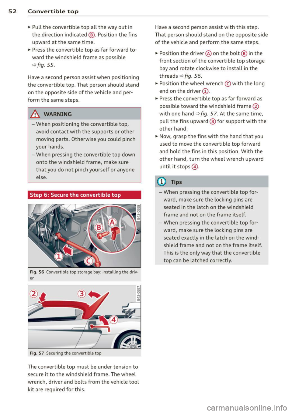
• Pull the convertible top all the way out in
the direction indicated @. Position the fins
upward at the same time.
• Press the convert ible top as far forward to
ward the windshield frame as possible
c>fig . 55.
Have a second person assist when positioning
the convertible top. That person should stand
on the oppos ite side of the veh icle and per
form the same steps.
A WARNING
-When positioning the conve rtible top,
avoid contact with the supports or other
moving parts. Otherw ise you could pinch
yo ur hands.
- When pressing the convert ible top down
onto the windshield frame, make sure
that you do not pinch yourself or anyone
else.
Step 6: Secure the convertible top
-
Fig. 56 Co nve rtible top storage bay: install ing the driv
e r
Fig. 57 Securing the conve rt ible top
The convertible top must be under tension to
secure it to the windshield frame . The wheel
wrench, dr iver and bolts from the vehicle tool
kit are required for this. Have a second person assist with this step
.
Tha t person should stand on the opposite side
of the vehicle and perform the same steps.
• Posit ion the driver @ on the bolt @ in the
front section of the convert ible top storage
bay and rotate clockwise to install in the
threads
c> fig. 56.
• Posit ion the wheel wrench © with the long
end on the driver @.
• Press the convertible top as far forward as
possible toward the windsh ield frame @
with one hand
c> fig. 57 . At the same time,
pull the fins upward @ for support with the
other hand.
• Now, grasp the fins with the hand that you
used to move the convertib le top forward
and hold the fins in this position . With the
other hand, turn the wheel wrench upward
until it stops @.
(0 Tips
-When pressing the convertible top for
ward, make sure the locking pins are
seated in the latch on the windshield
frame and not on the frame itself.
- When pressing the convert ible top for
ward, make sure the locking pins are
seated exactly in the latch on the wind
shield frame and not on the frame itself
This is the only way that the convertib le
top can be latched correctly .
Page 55 of 244
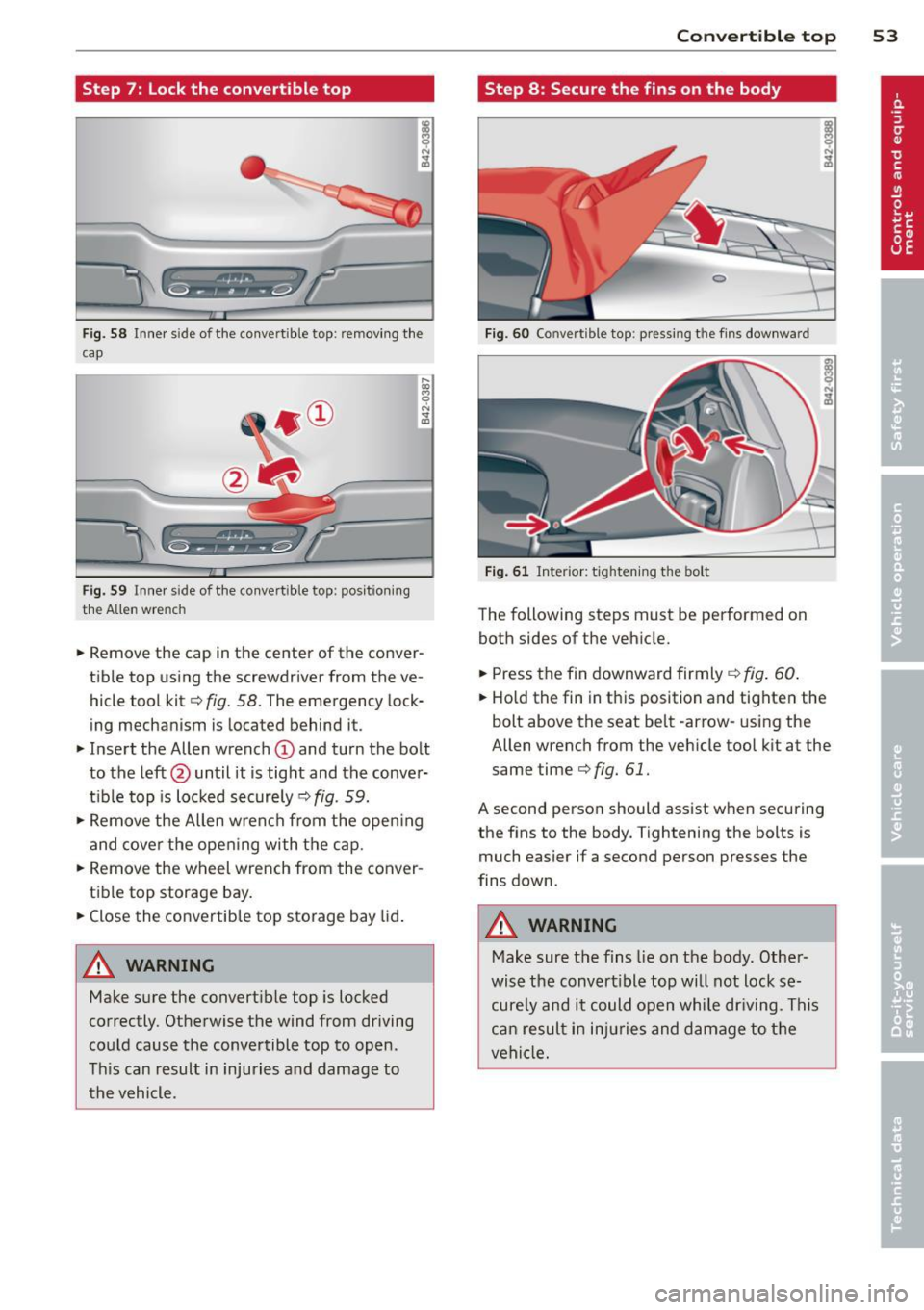
Step 7: Lock the convertible top
Fig. 58 Inner s ide of the conve rtible top: remov ing the
cap
Fig. 59 Inner s ide of the co nvertible top : pos ition ing
the Allen wrench
.. Remove the cap in the center of the conver
tib le top using the screwdriver from the ve
hicle tool kit¢
fig. 58. The emergency lock
ing mechanism is located behind it.
.. Insert the Allen wrench
(D and turn the bolt
to the left@ until it is tight and the conver
t ibl e top is locked securely ¢
fig. 59.
.,. Remove the Allen w rench from the open ing
and cover the opening with the cap.
.,. Remove the wheel wrench from the conver
tible top storage bay .
.. Close the convertible top storage bay lid.
A WARNING
Make sure the convert ible top is locked
correctly. Otherwise the wind from driving
could cause the convertible top to open.
This can result in injuries and damage to
the vehicle.
-
Convertible top 53
Step 8 : Secure the fins on the body
Fig . 60 Co nvert ible top: pressing t he fins downward
Fig. 61 Interior: t ighten ing the bolt
The following steps must be performed on
both sides of the vehicle .
.. Press the fin downward firmly
¢fig . 60.
.. Ho ld the fin in this position and tighten the
bolt above the seat belt -arrow-using the
Allen wrench from the veh icle tool k it at the
same time¢
fig. 61.
A second person should assist when securing
the fins to the body. Tightening the bolts is
much easier if a second person presses the
fins down.
A WARNING
-Make sure the fins lie on the body . Other-
wise the convert ible top will not lock se
cure ly and it could open while dr iving. This
can resul t in injuries and damage to the
vehicle.
-
Page 56 of 244
54 Convertible top
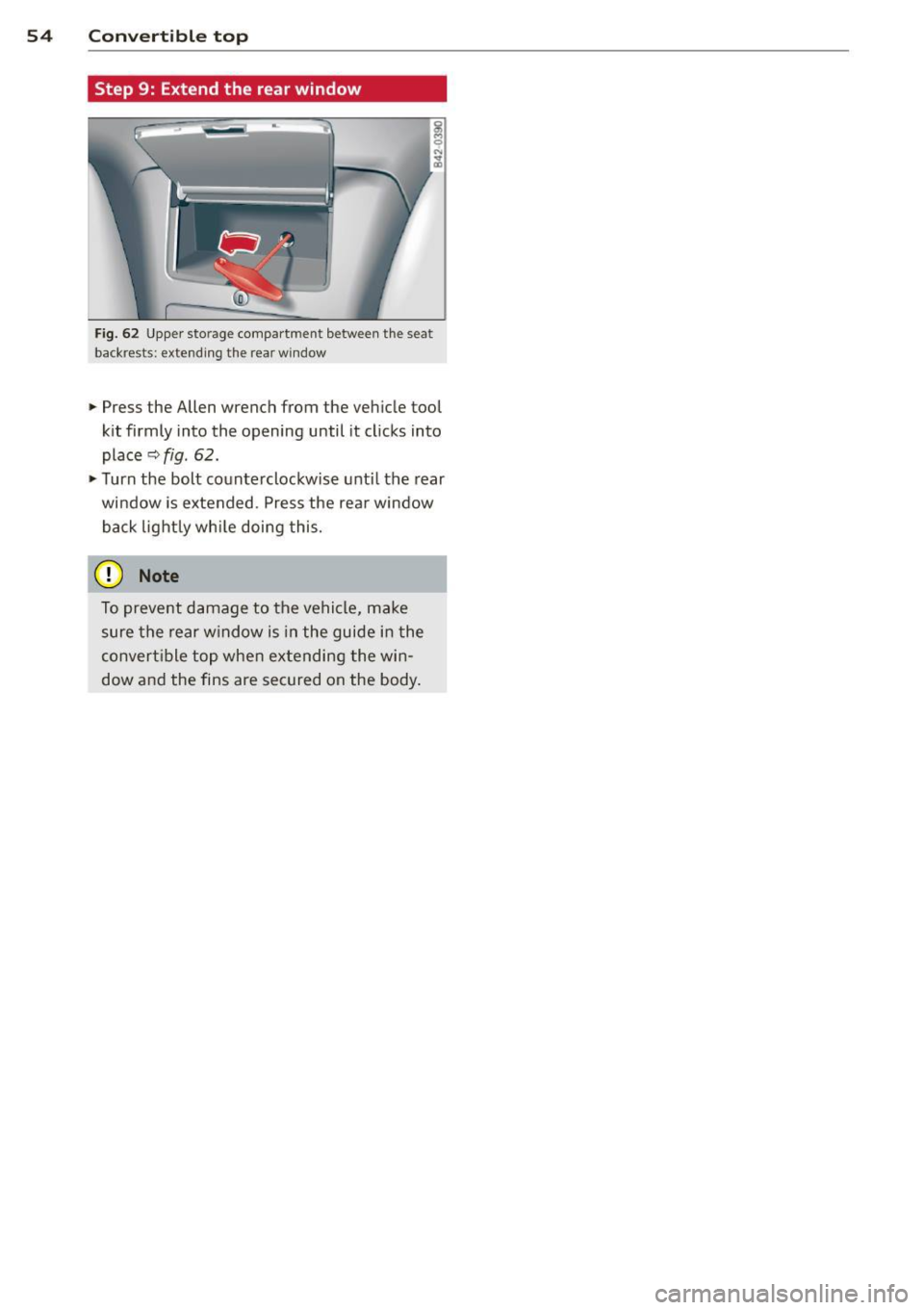
Step 9: Extend the rear window
Fig. 62 Upper storage compartment between the seat
backrests: extending the rear window
~ Press the Allen wrench from the vehicle tool
kit firmly into the opening until it clicks into
place
~ fig. 62.
~ Turn the bolt counterclockwise until the rear
window is extended. Press the rear window
back lightly while doing this.
0 Note
To prevent damage to the vehicle, make
sure the rear window is in the guide in the
convertible top when extending the win
dow and the fins are secured on the body.
Page 57 of 244
Clear vision Lights
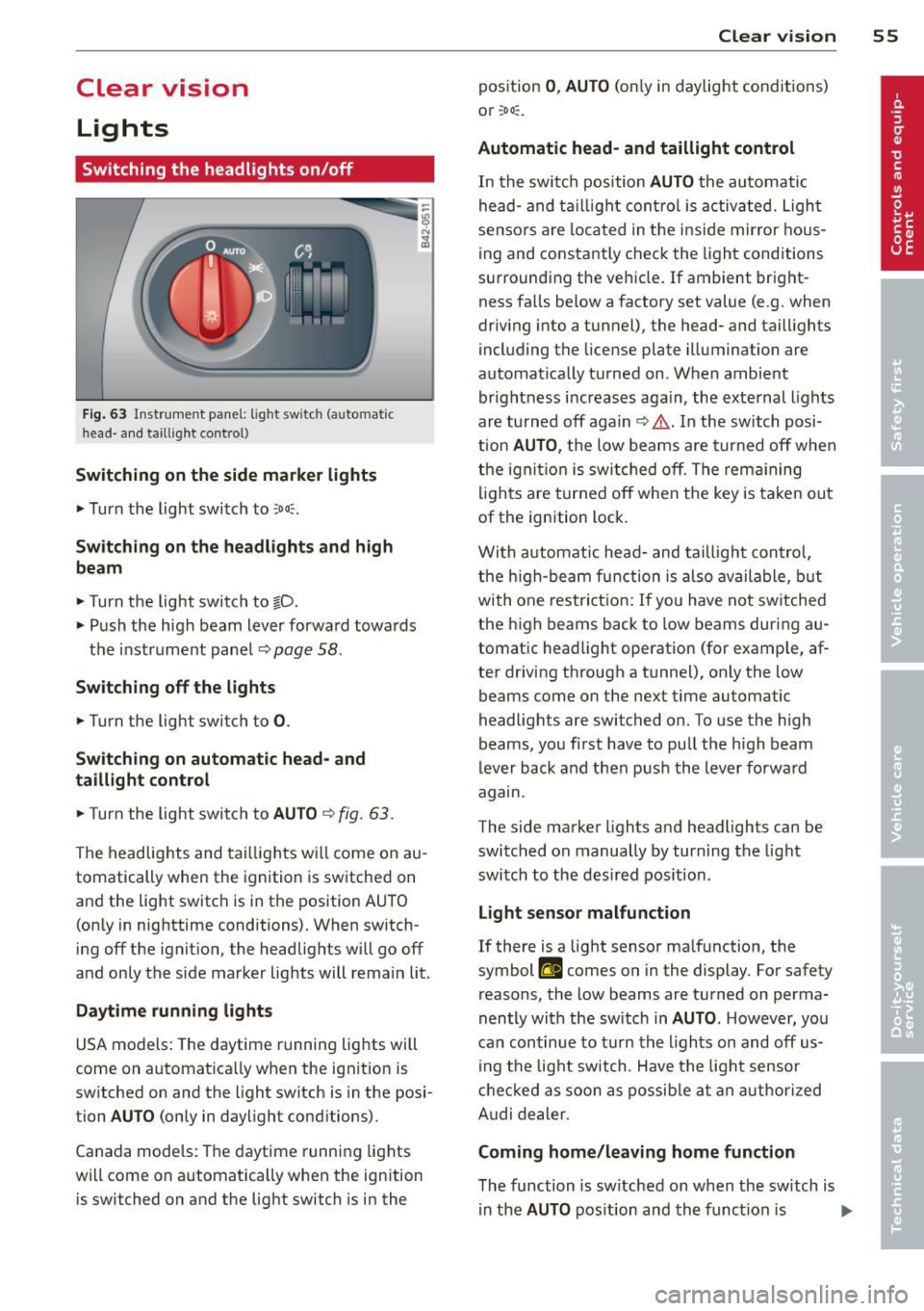
Switching the headlights on/off
Fig. 63 In str ume nt pa ne l: lig ht sw itc h (auto mat ic
head· a nd ta ill ig ht control)
Switching on the side marke r lights
... Turn the light switch to :oo::.
Switching on the headlights and high
beam
... Turn the light switch to §D.
.,. Push the h igh beam lever forwa rd towa rds
t h e instrument panel~
page 58 .
Sw itching off the lights
.,. Turn the light switch to 0 .
Sw itching on automatic head- and
taillight control
.,. Turn the light switch to AUTO ~ fig. 63 .
The headlig hts and tai lligh ts w ill come on au
tomatically when the ignition is sw itche d on
and the light switch is in the position AU TO
(on ly in nig httime conditions). When switch·
ing off the ignit io n, the headlig hts wi ll go off
and only the side marker lights will remai n lit.
Daytime running lights
USA models: The daytime r unning lig hts will
come on a utomat ica lly when the ig nition is
sw itched on and the light switch is in the posi·
tion
AUTO (only in daylight conditions).
Canada models : Th e daytime runni ng lights
will come on a utomat ically when the ignition
is switched on and the light switch is in the
Clear vi sion 55
position 0 , AUTO (on ly in daylight conditions)
or ;oo :.
Automatic head- and taillight control
In the swi tch position AUTO the au tomati c
he ad- and t aillight con tro l is activ ated. Ligh t
senso rs ar e loca ted in t he i nside mir ro r h ous
ing and co nstantly chec k the light cond itions
su rroundi ng the vehicle. If ambient bright
ness fa lls below a factory set value (e .g. when
dr iv ing into a tunnel), the head- and tail lights
i ncl uding the license plate illuminati on are
automat ica lly t urned on . When ambient
brightness i ncreases aga in, the exte rnal ligh ts
ar e turned off aga in
c> &. . In the switch posi
t ion
AUTO , the low beams are tur ned off when
th e ign ition is swi tched o ff. Th e rem aining
li gh ts are turned off when the key is ta ke n out
of the ignition lock.
W it h a utomat ic head- and taill igh t con trol,
t he h igh-beam fu nction is also ava ilable , bu t
with one rest ric t ion : If you have not sw itche d
the h igh beams back to low beams during a u
tomat ic head light operat ion (for examp le, af
ter driving through a tunnel), on ly the low
beams come on the next time automatic
headlig hts are switched on. To use the high
beams, yo u fi rst have to pull the h igh beam
lever back and then push the lever forwa rd
agam .
The side ma rke r lights a nd headlights ca n be
sw itc hed on manually by turn ing the light
swi tc h to the des ired pos ition .
Light sensor malfunction
If there is a light sensor ma lfunction, the
symbol
II comes on in the display . For safety
reasons, the low beams are tu rned on perma
nently with t he sw itch in
AUTO . However, you
can con tinue to tu rn the lights on and off us
in g t he light switch . Have t he ligh t sensor
c h eck ed as soon a s possib le a t an au thorized
A udi dealer.
Coming home/leaving home function
The function is sw itched on when the sw itch is
i n the
AUTO pos ition and th e funct ion is liJJ,,
Page 58 of 244
56 Clear vision
shown as active in the driver information
system.
The
coming home function illuminates the
area around the vehicle when the ignition is
switched off and the driver's door is opened.
The length of time the lights remain on can be
set in the menu display
(Lights> Exterior
lights> coming home) .
The leaving home function illuminates the
area around the vehicle when unlocking it.
.&_ WARNING
- Never use daytime running lights to see
where you are going. They are not bright enough and will not let you see far
enough ahead for safety, especially at dusk or when it is dark. Be aware of
changes in outside light conditions when
you are driving and respond by switching
on your low beams.
- Automatic head- and taillight control is
only intended to assist the driver. This
feature does not relieve the driver of his
responsibility to check the headlights
and to turn them on manually according
to the current light and visibility condi
tions. For example, fog and rain cannot be detected by the light sensors. Conse
quently, always switch the headlights on
under these weather conditions and
when driving in the dark.
- Crashes can happen when you cannot see
the road ahead and when you cannot be
seen by other motorists.
-Always turn on the headlights so that you can see ahead and so that others can see your car from the back.
(D Tips
- Always observe the specific local regula
tions for your area when to use your
lights .
- Turn on low beams as evening ap
proaches or in conditions of poor visibili
ty.
- Do not attach stickers to the windshield
in front of the sensors as this can disable the automatic head- and
taillight control
and the automatic glare-dimming of the
rearview mirror(s)*.
- If you
remove the ignition from the igni
tion lock while the headlights are still
on, a buzzer will sound as long as the
driver's door is open to remind you to
turn off the lights.
- In the AUTO mode, the low beams are
turned off when the ignition is turned
off. The remaining lights are turned off
when the key is taken out of the ignition .
- In cool or damp weather conditions the
headlights may fog
over temporarily on
the inside.
- The critical factor is the temperature
difference between the interior and the
exterior of the headlight lens.
- With the main beams switched on, the
light-emitting area will be free of con
densation after a short time, however
the edges of the glass may still be fog
ged.
- This physical phenomenon has no ef
fect on the life of your vehicle's light
ing system.
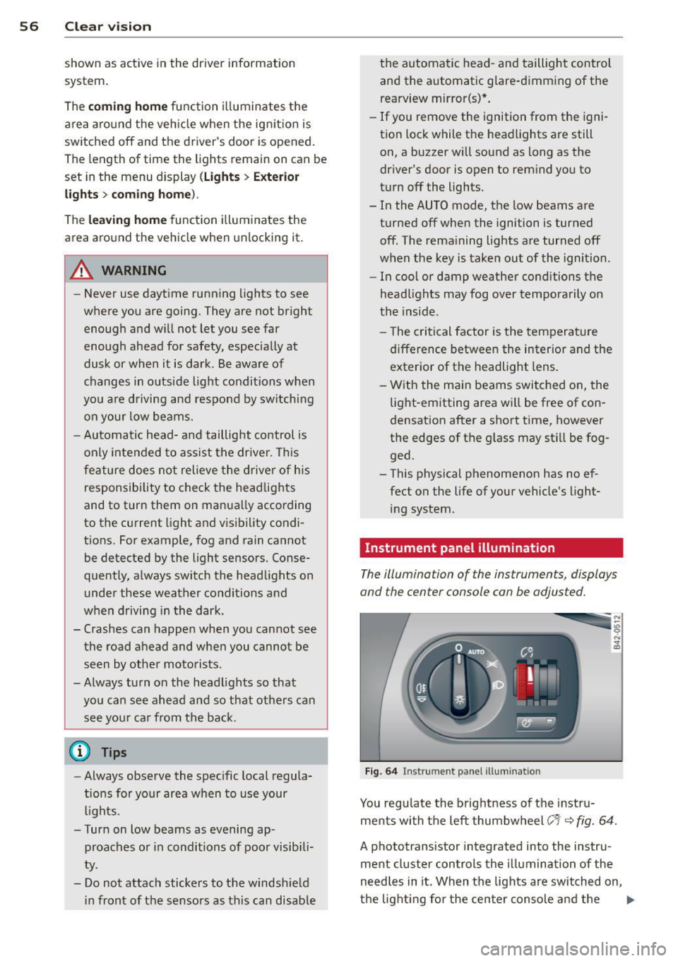
Instrument panel illumination
The illumination of the instruments, displays
and the center console can be adjusted.
Fig. 64 Instrument panel illumination
You regulate the brightness of the instru
ments with the left thumbwheel
(-'1· ~ fig. 64.
A phototransistor integrated into the instru
ment cluster controls the illumination of the
needles in it. When the lights are switched on,
the lighting for the center console and the
llll>
Page 59 of 244
instruments (needles and dials) is automati
cally adjusted to ambient conditions. The driv
er can a lso ad just the brightness of the light
ing.
Ignition ON , light switch at @
With the ignition swi tched O N, the glow of in
strument needles
can be adjusted to appear
brighter or dimmer.
Ignition ON , light switch at coo; or gD .
With the l igh ts sw itched on, the bright ness of
in str ument cluster (i.e. needles, g auges and
disp lays) and center console i llumination can
be adjusted .
(D Note
The inst rument cl uster and cente r console
illum ination (ga uges and needles) comes
on when you switch on the ignition and the
vehicle headlights are off. Be aware of t he
following difference between mode ls built
to US or Canadian specifications:
- USA models: illumination of the inst ru
ment cluster (ga uges and needles), das h
and center console around the gearsh ift
l ever is controlled by a light senso r locat
ed in the instrument panel. The instru
m ent pane l illumination will a utomat i
call y become dimmer as t he day ligh t
fades away and eventually will go o ut
com plete ly when o utside light is ve ry
l ow. This is to rem ind you, the driver, to
switch on the headlights before it gets
too dark .
- Canada mode ls: instrument panel i llum i
nat ion will stay bright regard less of the
i ntensity of amb ient light. Always be
aware of c hanges in outside light cond i
t ions wh ile you are driving. Respond in
time to fadi ng daylight by tu rning the
l ight sw itch to posit ion
io (or "AUTO" if
you r ca r is equ ipped with th is featu re) to
turn on your hea dligh ts. Clear vi
sion 5 7
Emergency flasher
The emergency flasher makes other motorists
aware that you or your vehicle are in an emer
gency situation .
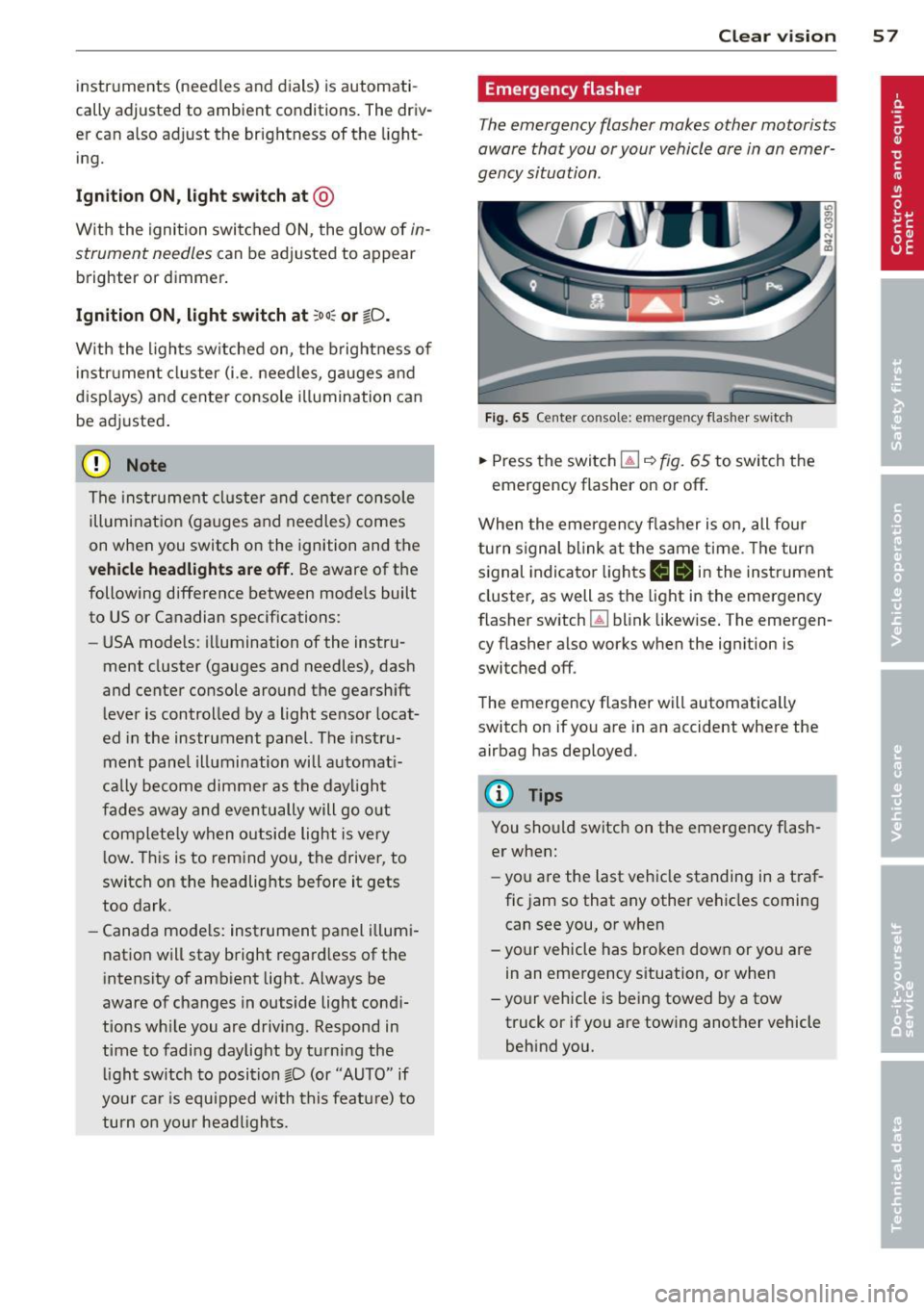
Fig. 65 Cent er consol e: eme rge ncy flas he r sw itc h
.,. Press the switc h l!J ~ fig. 65 to switch t he
emergency flasher on or off.
When the eme rgency f las her is on, all four
turn s ignal b link at t he same time . Th e turn
signal indicato r lights
1111 in t he instrument
cluster, as well as the light in the eme rgency
flasher switch ~ blink likew ise . The emergen
cy flasher also works when the ignition is
switched off .
The eme rgency flasher will automatically
switch on if you are in an accident where the
airbag has deployed.
@ Tips
You sho uld switch on the emergency flash
er when:
- you a re the last ve hicle standing in a t ra f
fic jam so that any other vehicles coming
can see you, or when
- yo ur vehicle has bro ken dow n or you are
in an eme rgency s ituation, or when
- yo ur vehicle is be ing towed by a tow
truck or if you are towing another vehicle
behind you.
Page 60 of 244
58 Clear vis ion
Turn signals and high beam lever
The lever is used to operate the turn signals
and the high beam as well as the headlight
flasher .
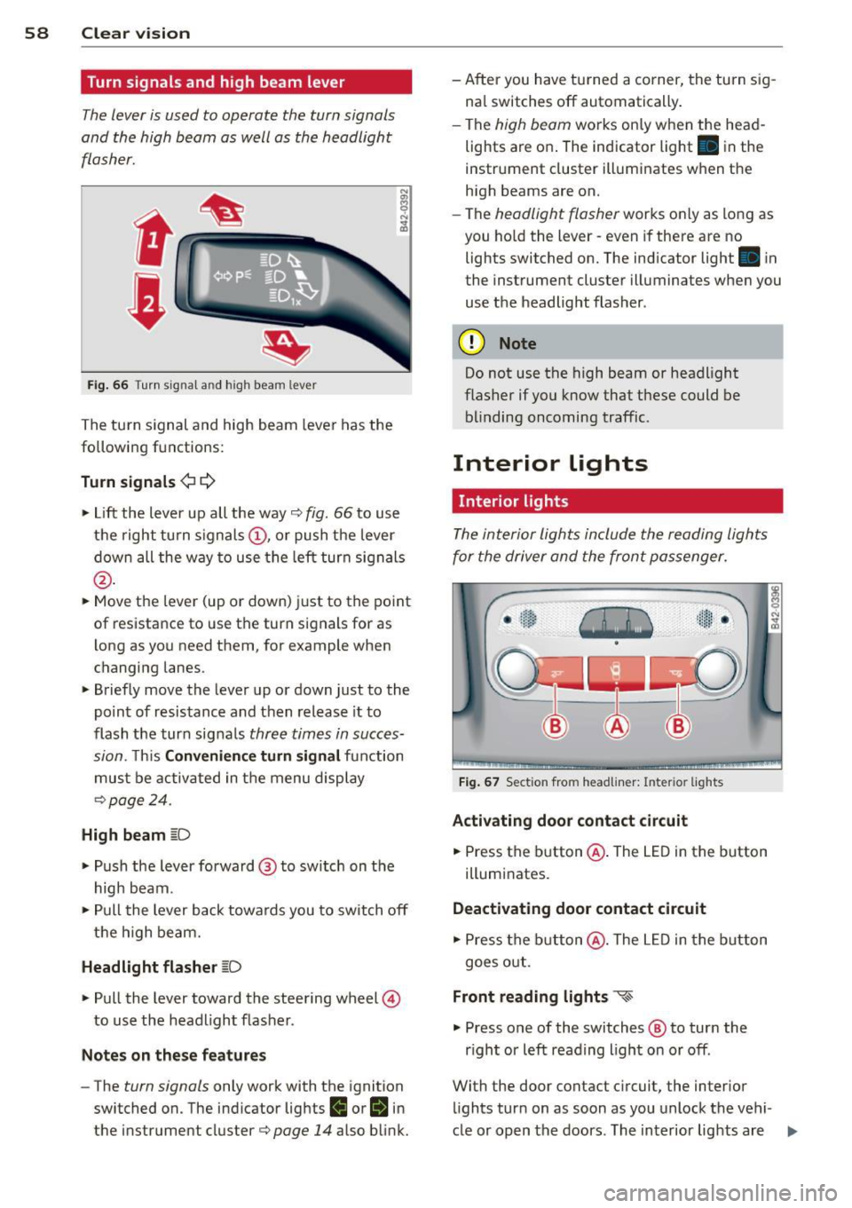
Fig. 66 Turn s igna l and high beam lever
The turn s ignal and high beam leve r has the
following functions:
Turn signals ¢ c::>
"" Lift the lever up all the way¢ fig. 66 to use
the right turn signals @, or push the lever
down all the way to use the left turn signals
@ .
""Move the lever (up or down) just to the point
of resistance to use the turn signals for as
l ong as you need them, for example when
changing lanes.
"" Briefly move the lever up or down just to the
po int of resistance and then release it to
flash the turn signals
three times in succes
sion.
T his Convenience turn signal function
must be activated in the menu display
¢ page 24.
High beam [D
"" Push the lever forward @ to switch on the
high beam.
"" Pull the lever back towards you to switch off
the high beam.
Headlight flasher [D
"" Pull the lever toward the steering wheel @
to use the headlight flasher.
Notes on these features
- The turn signals only work with the ignition
switched on. The indicator lights
II or II in
t he instrument cluster¢
page 14 also blink. - After you have turned a corner, the turn sig
na l switches off automatically .
- The
high beam works only when the head
lights are on . The indicator light. in the
instrument cluster illuminates when the
high beams are on.
- The
headlight flasher works on ly as long as
you ho ld the lever -even if there a re no
lights switched on. The indicator light . in
the instrument cluster illuminates when you
use the headlight flasher.
(D Note
Do not use the high beam or headlight
flasher if you know that these could be
blinding oncoming traffic.
Interior Lights
Interior light s
The interior lights include the reading lights
for the driver and the front passenger.
Fig. 67 Sect ion from headliner: Interior lights
Activating door contact circuit
.,. Press the button@. The LED in the button
illumi nates.
Deactivating door contact circuit
"" Press the button @. The LED in the button
goes out.
Front reading lights ~
"" Press one of the switches @ to turn the
r ight or left reading l ight on or off.
With the door contact circuit, the interior
lights tur n on as soon as you unlock the vehi-
cle or open the doors. The interior lights are
Ill>