CHERY TIGGO 2009 Service Repair Manual
Manufacturer: CHERY, Model Year: 2009,
Model line: TIGGO,
Model: CHERY TIGGO 2009
Pages: 1903, PDF Size: 33.38 MB
CHERY TIGGO 2009 Service Repair Manual
TIGGO 2009
CHERY
CHERY
https://www.carmanualsonline.info/img/53/56852/w960_56852-0.png
CHERY TIGGO 2009 Service Repair Manual
Trending: headlights, 4WD, oil dipstick, mileage, ABS, maintenance reset, sunroof
Page 1781 of 1903
Downloaded from www.Manualslib.com manuals search engine High Mounted Stop Lamp
Removal & Installation
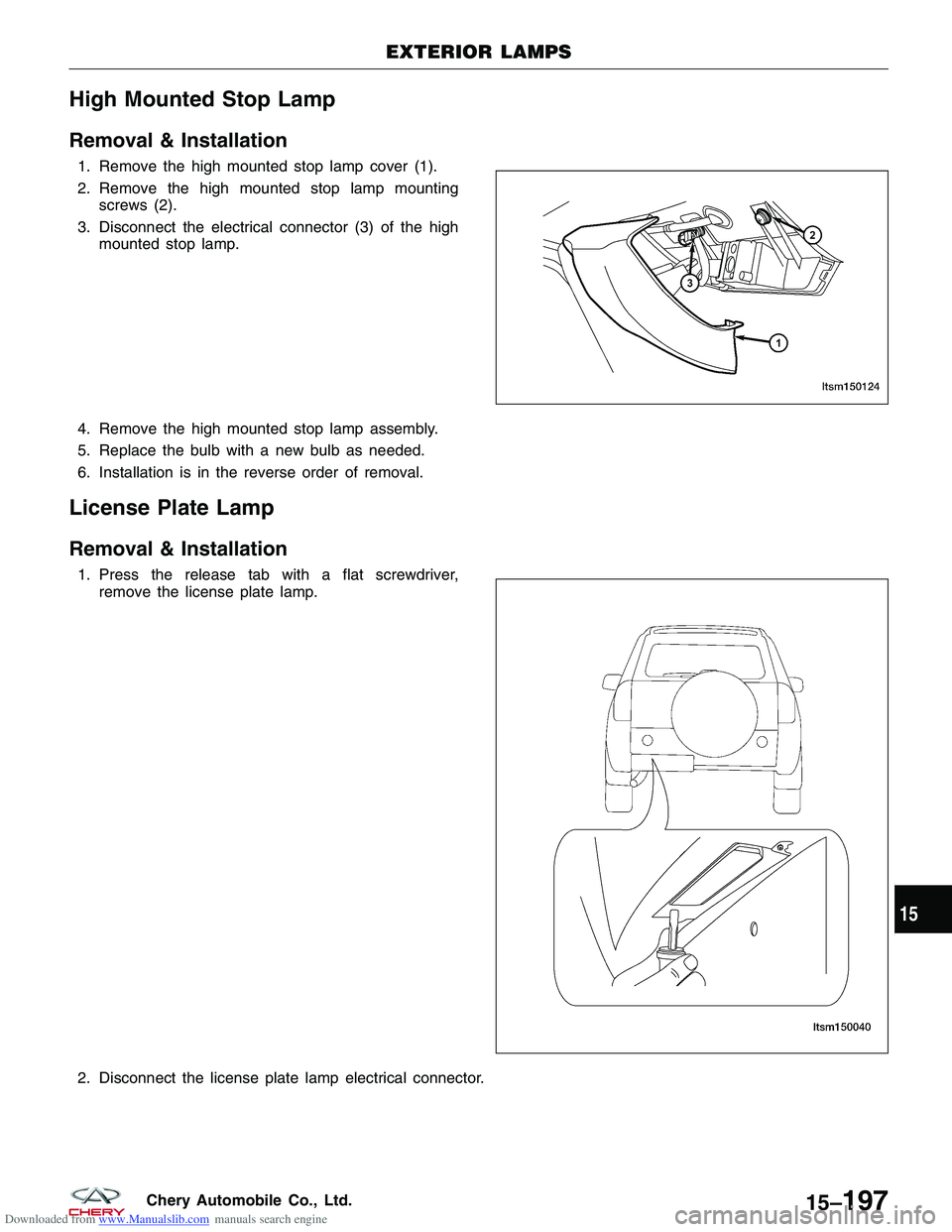
1. Remove the high mounted stop lamp cover (1).
2. Remove the high mounted stop lamp mountingscrews (2).
3. Disconnect the electrical connector (3) of the high mounted stop lamp.
4. Remove the high mounted stop lamp assembly.
5. Replace the bulb with a new bulb as needed.
6. Installation is in the reverse order of removal.
License Plate Lamp
Removal & Installation
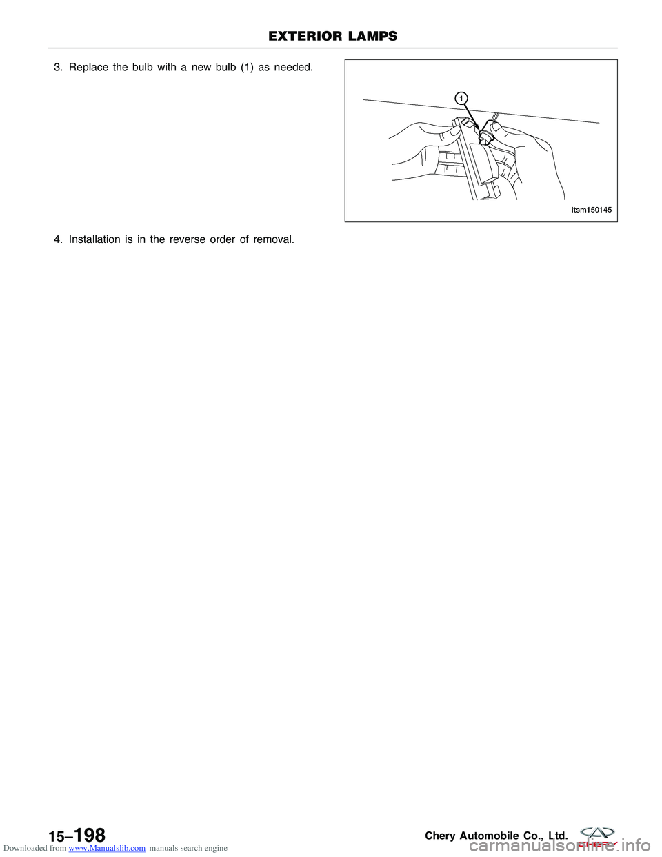
1. Press the release tab with a flat screwdriver, remove the license plate lamp.
2. Disconnect the license plate lamp electrical connector.
EXTERIOR LAMPS
LTSM150124
LTSM150040
15
15–197Chery Automobile Co., Ltd.
Page 1782 of 1903
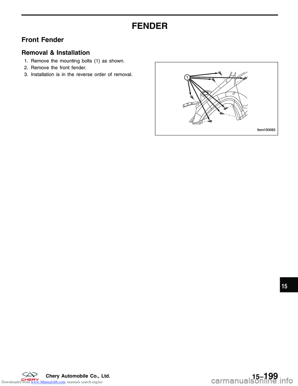
Downloaded from www.Manualslib.com manuals search engine 3. Replace the bulb with a new bulb (1) as needed.
4. Installation is in the reverse order of removal.
EXTERIOR LAMPS
LTSM150145
15–198Chery Automobile Co., Ltd.
Page 1783 of 1903
Downloaded from www.Manualslib.com manuals search engine FENDER
Front Fender
Removal & Installation
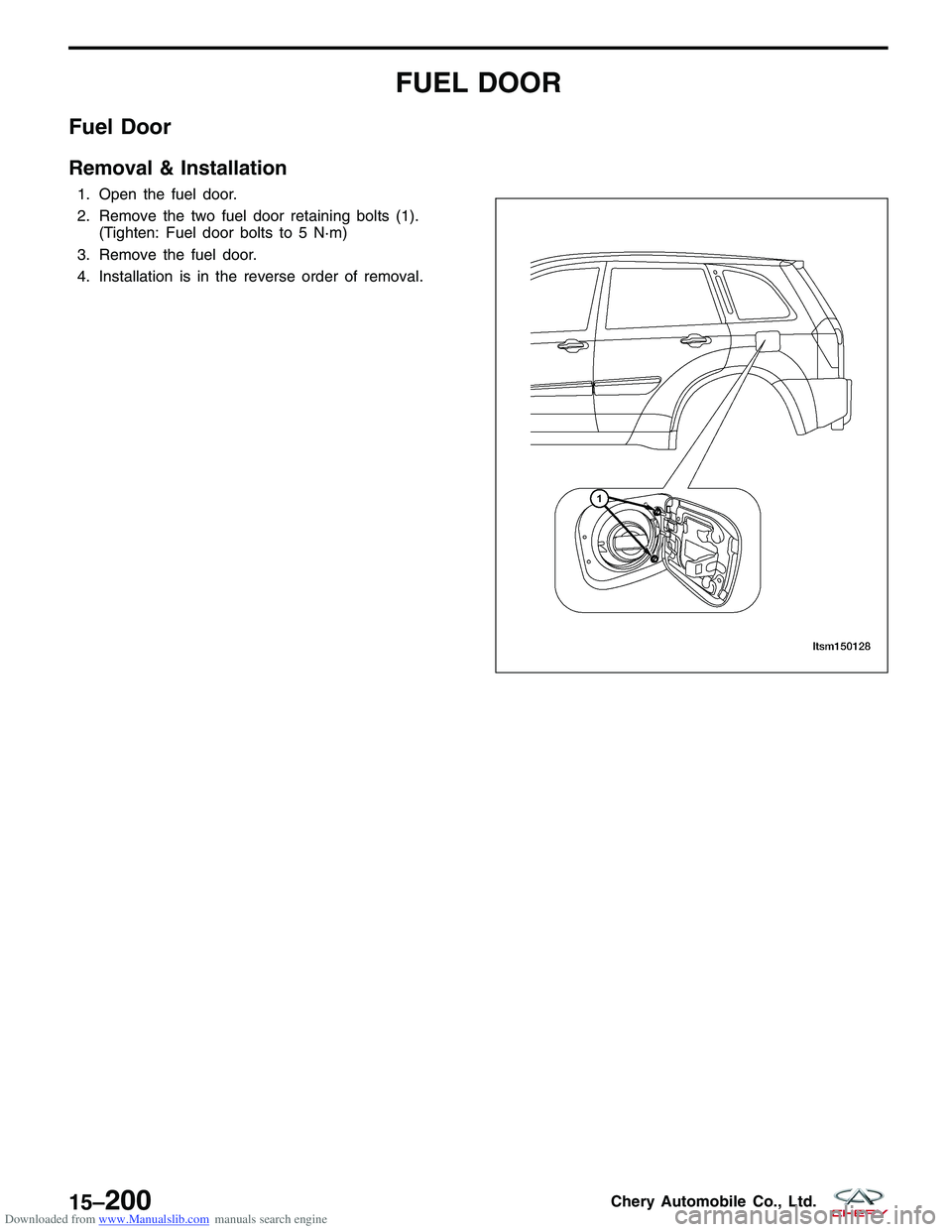
1. Remove the mounting bolts (1) as shown.
2. Remove the front fender.
3. Installation is in the reverse order of removal.
LTSM150083
15
15–199Chery Automobile Co., Ltd.
Page 1784 of 1903
Downloaded from www.Manualslib.com manuals search engine FUEL DOOR
Fuel Door
Removal & Installation
1. Open the fuel door.
2. Remove the two fuel door retaining bolts (1).(Tighten: Fuel door bolts to 5 N·m)
3. Remove the fuel door.
4. Installation is in the reverse order of removal.
LTSM150128
15–200Chery Automobile Co., Ltd.
Page 1785 of 1903
Downloaded from www.Manualslib.com manuals search engine GRILLE
Grille
Removal & Installation
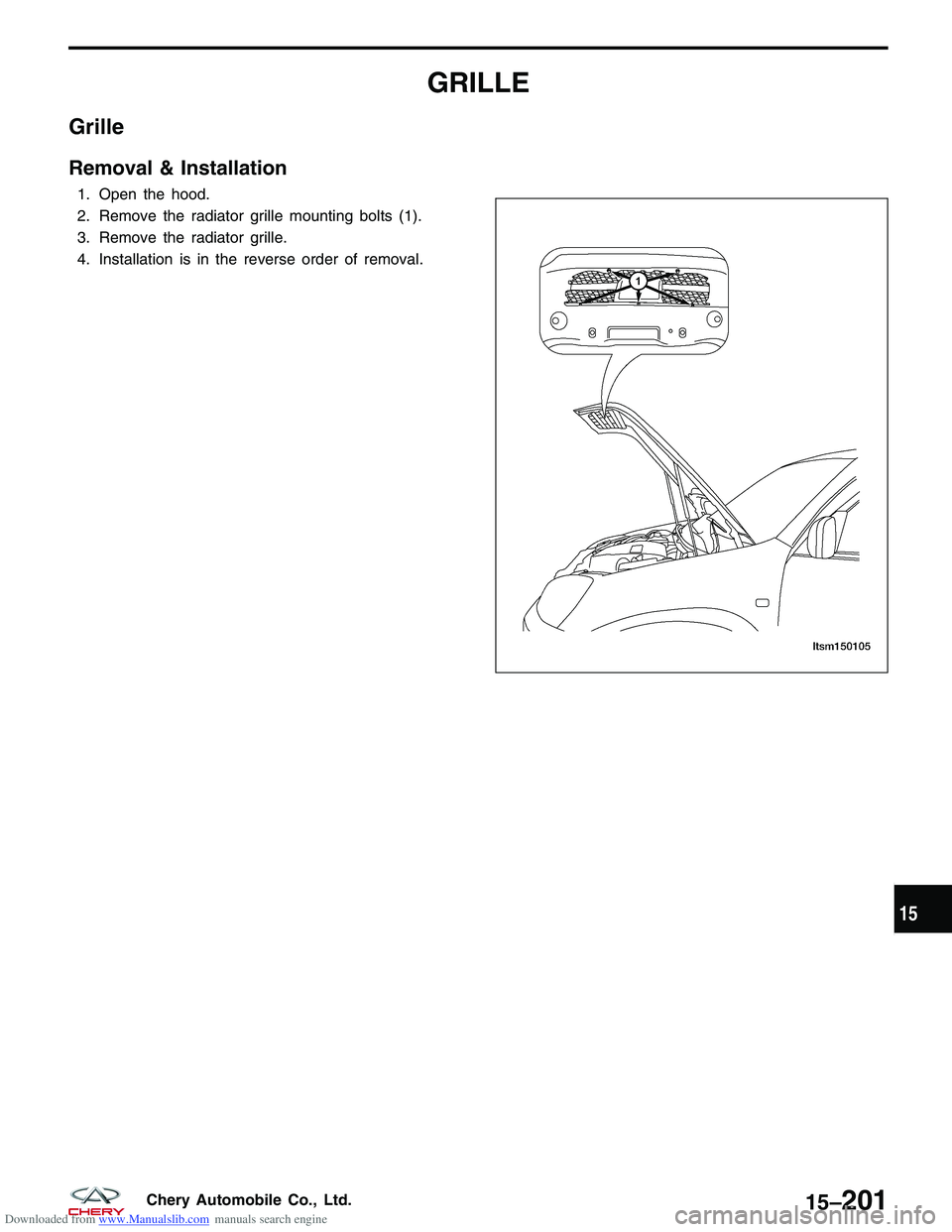
1. Open the hood.
2. Remove the radiator grille mounting bolts (1).
3. Remove the radiator grille.
4. Installation is in the reverse order of removal.
LTSM150105
15
15–201Chery Automobile Co., Ltd.
Page 1786 of 1903
Downloaded from www.Manualslib.com manuals search engine HOOD
Hood
Removal & Installation
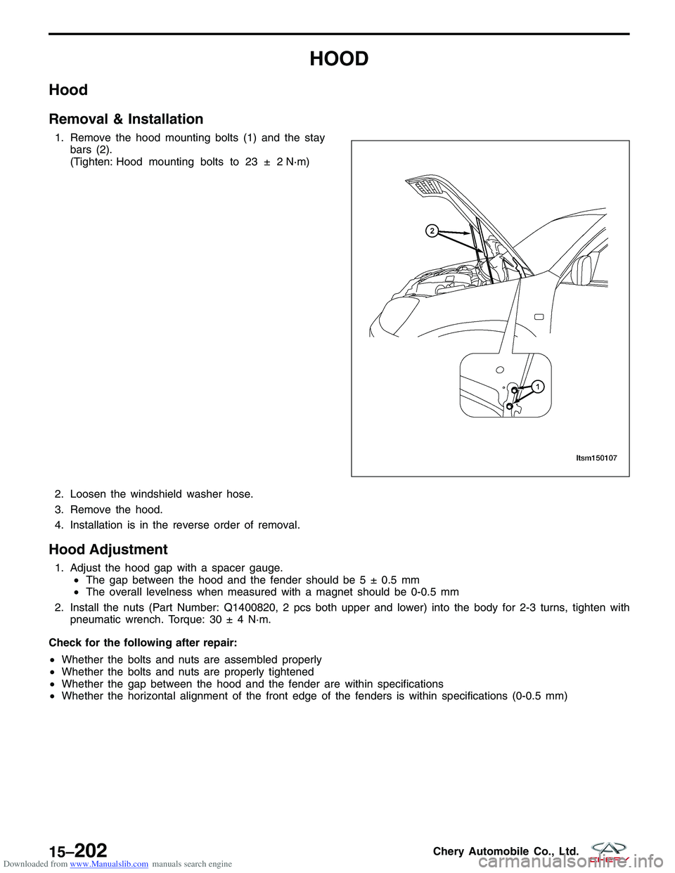
1. Remove the hood mounting bolts (1) and the staybars (2).
(Tighten: Hood mounting bolts to 23 ± 2 N·m)
N·m)
2. Loosen the windshield washer hose.
3. Remove the hood.
4. Installation is in the reverse order of removal.
Hood Adjustment
1. Adjust the hood gap with a spacer gauge. •The gap between the hood and the fender should be 5 ± 0.5 mm
• The overall levelness when measured with a magnet should be 0-0.5 mm
2. Install the nuts (Part Number: Q1400820, 2 pcs both upper and lower) into the body for 2-3 turns, tighten with pneumatic wrench. Torque: 30 ± 4 N·m.
Check for the following after repair:
• Whether the bolts and nuts are assembled properly
• Whether the bolts and nuts are properly tightened
• Whether the gap between the hood and the fender are within specifications
• Whether the horizontal alignment of the front edge of the fenders is within specifications (0-0.5 mm)
LTSM150107
15–202Chery Automobile Co., Ltd.
Page 1787 of 1903
Downloaded from www.Manualslib.com manuals search engine Hood Release Cable
Removal & Installation
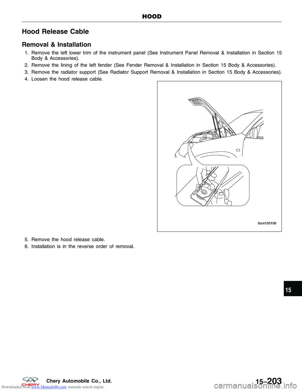
1. Remove the left lower trim of the instrument panel (See Instrument Panel Removal & Installation in Section 15Body & Accessories).
2. Remove the lining of the left fender (See Fender Removal & Installation in Section 15 Body & Accessories).
3. Remove the radiator support (See Radiator Support Removal & Installation in Section 15 Body & Accessories).
4. Loosen the hood release cable.
5. Remove the hood release cable.
6. Installation is in the reverse order of removal.
HOOD
LTSM150108
15
15–203Chery Automobile Co., Ltd.
Page 1788 of 1903
Downloaded from www.Manualslib.com manuals search engine LUGGAGE RACK
Luggage Rack
Removal & Installation
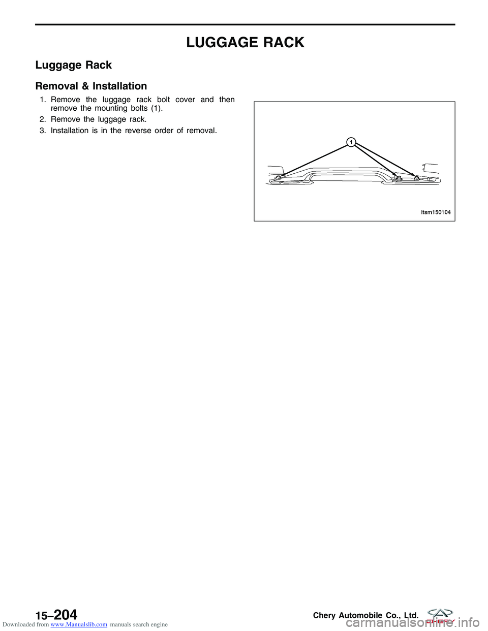
1. Remove the luggage rack bolt cover and thenremove the mounting bolts (1).
2. Remove the luggage rack.
3. Installation is in the reverse order of removal.
LTSM150104
15–204Chery Automobile Co., Ltd.
Page 1789 of 1903
Downloaded from www.Manualslib.com manuals search engine SPARE TIRE SUPPORT
Spare Tire Support
Removal & Installation
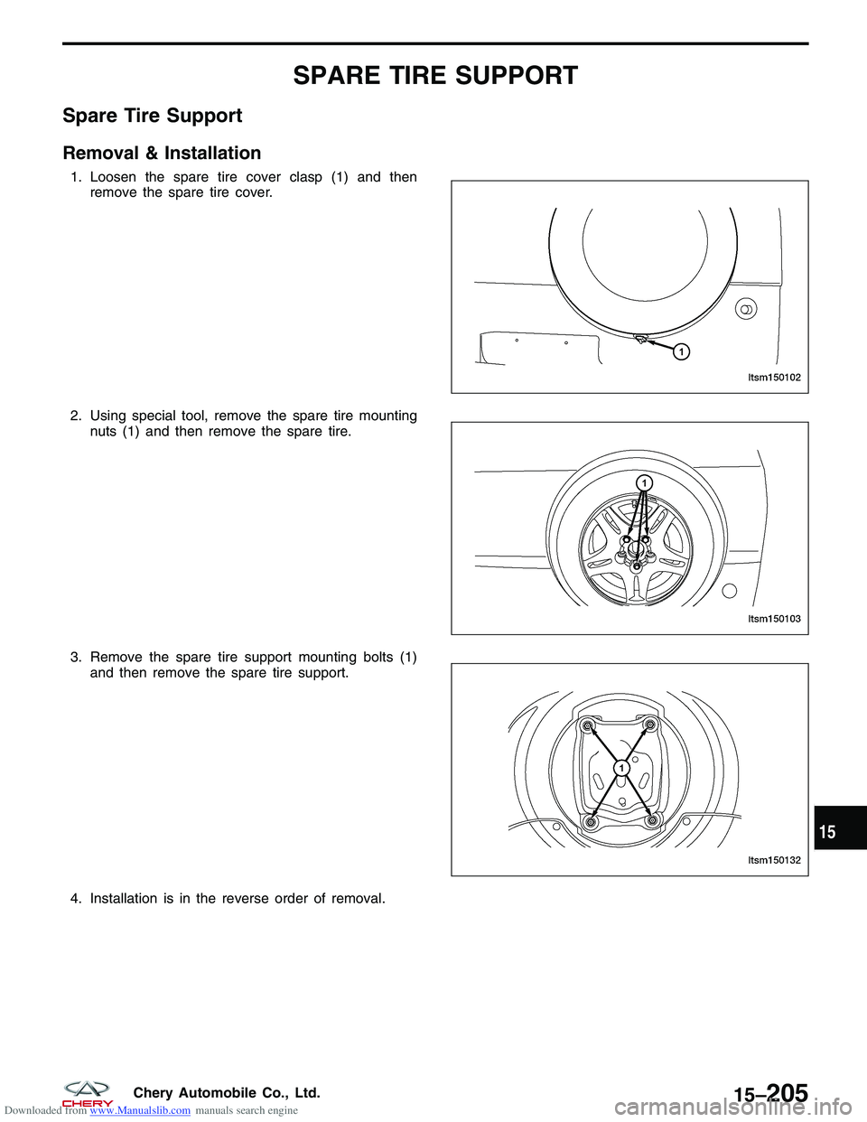
1. Loosen the spare tire cover clasp (1) and thenremove the spare tire cover.
2. Using special tool, remove the spare tire mounting nuts (1) and then remove the spare tire.
3. Remove the spare tire support mounting bolts (1) and then remove the spare tire support.
4. Installation is in the reverse order of removal.
LTSM150102
LTSM150103
LTSM150132
15
15–205Chery Automobile Co., Ltd.
Page 1790 of 1903
Downloaded from www.Manualslib.com manuals search engine HORN
Description
A dual note electric horn system is installed on this vehicle. The horn system features electromagnetic horns. The
horn system includes the following components:
•Horn - The horns are located inside the left front bumper.
• Horn Switch - The horn switch is located under the driver airbag.
Operation
The horn system circuit is designed so that the system will remain operational, regardless of the ignition switch posi-
tion.
15–206Chery Automobile Co., Ltd.
Trending: warning, odometer, parking brake, wipers, C1275, reset, oil reset
