CHERY TIGGO 2009 Service Repair Manual
Manufacturer: CHERY, Model Year: 2009,
Model line: TIGGO,
Model: CHERY TIGGO 2009
Pages: 1903, PDF Size: 33.38 MB
CHERY TIGGO 2009 Service Repair Manual
TIGGO 2009
CHERY
CHERY
https://www.carmanualsonline.info/img/53/56852/w960_56852-0.png
CHERY TIGGO 2009 Service Repair Manual
Trending: gas type, fuse, ad blue, service indicator, oil temperature, ECU, spark plugs
Page 1741 of 1903
Downloaded from www.Manualslib.com manuals search engine Body
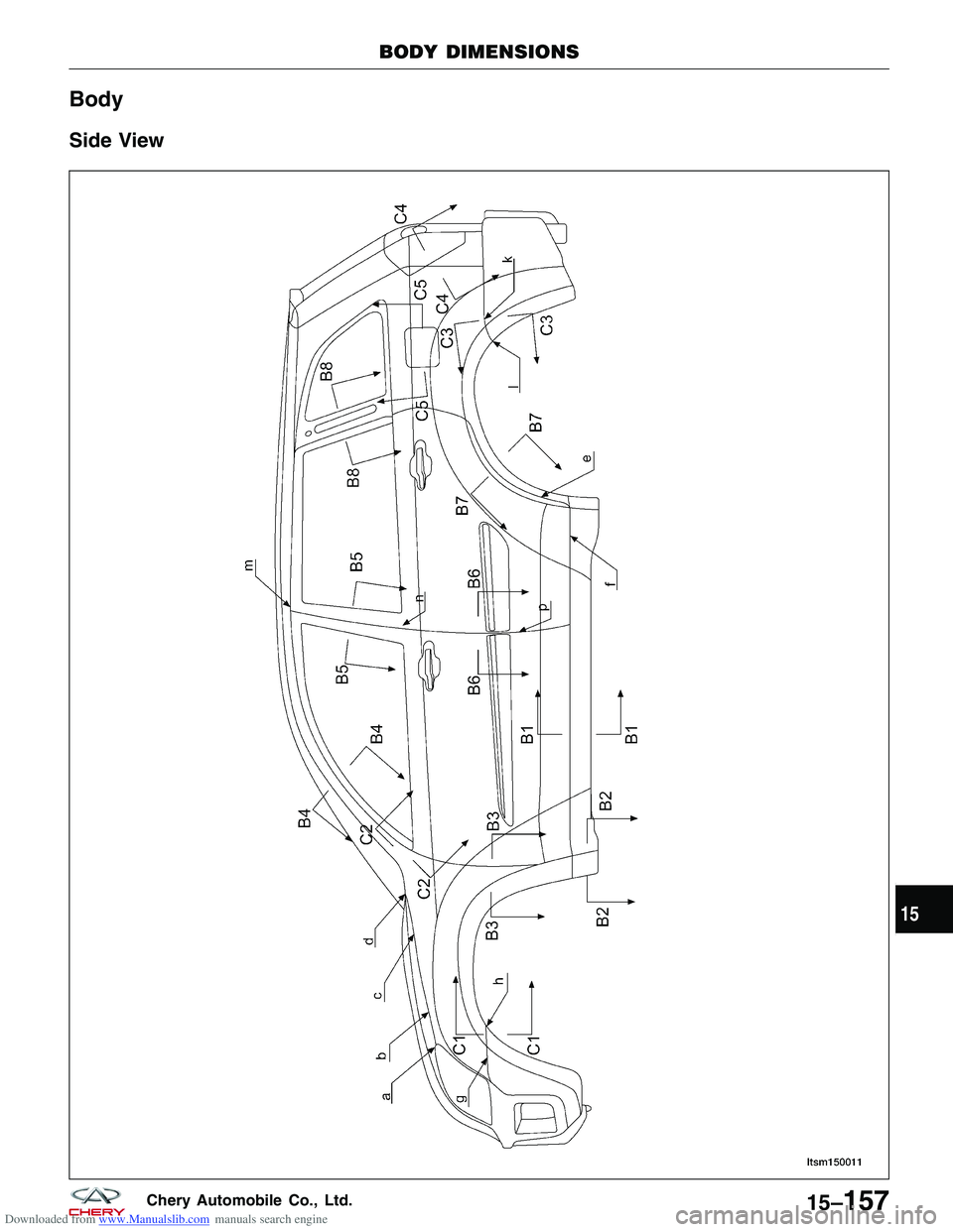
Side View
BODY DIMENSIONS
LTSM150011
15
15–157Chery Automobile Co., Ltd.
Page 1742 of 1903
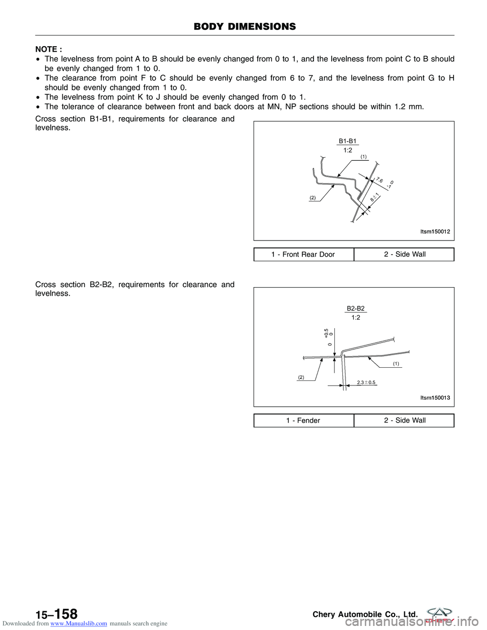
Downloaded from www.Manualslib.com manuals search engine NOTE :
•The levelness from point A to B should be evenly changed from 0 to 1, and the levelness from point C to B should
be evenly changed from 1 to 0.
• The clearance from point F to C should be evenly changed from 6 to 7, and the levelness from point G to H
should be evenly changed from 1 to 0.
• The levelness from point K to J should be evenly changed from 0 to 1.
• The tolerance of clearance between front and back doors at MN, NP sections should be within 1.2 mm.
Cross section B1-B1, requirements for clearance and
levelness.
Cross section B2-B2, requirements for clearance and
levelness.
1 - Front Rear Door 2 - Side Wall
1 - Fender2 - Side Wall
BODY DIMENSIONS
LTSM150012
LTSM150013
15–158Chery Automobile Co., Ltd.
Page 1743 of 1903
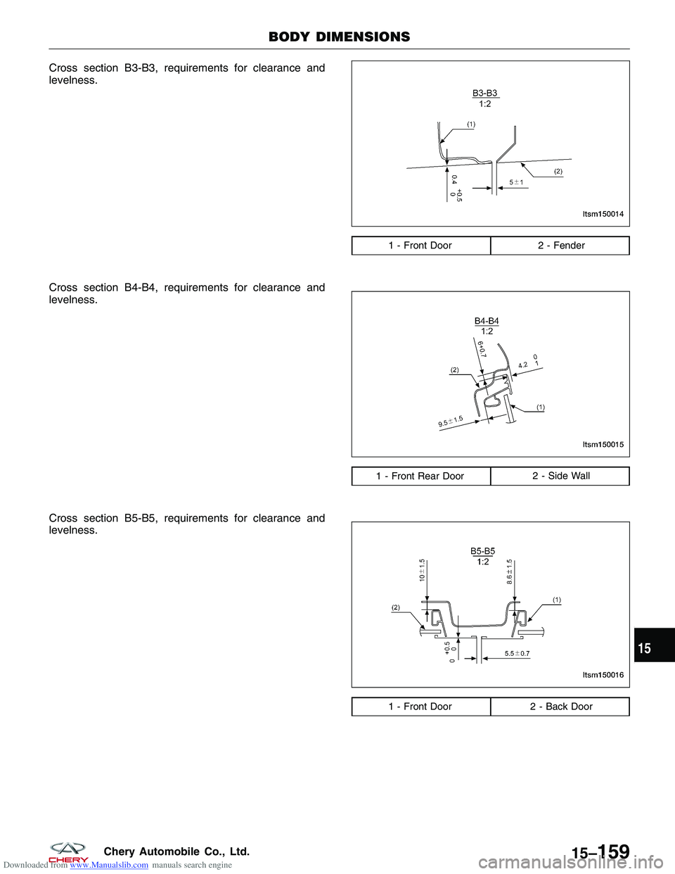
Downloaded from www.Manualslib.com manuals search engine Cross section B3-B3, requirements for clearance and
levelness.
Cross section B4-B4, requirements for clearance and
levelness.
Cross section B5-B5, requirements for clearance and
levelness.
1 - Front Door2 - Fender
1 - Front Rear Door 2 - Side Wall
1 - Front Door2 - Back Door
BODY DIMENSIONS
LTSM150014
LTSM150015
LTSM150016
15
15–159Chery Automobile Co., Ltd.
Page 1744 of 1903
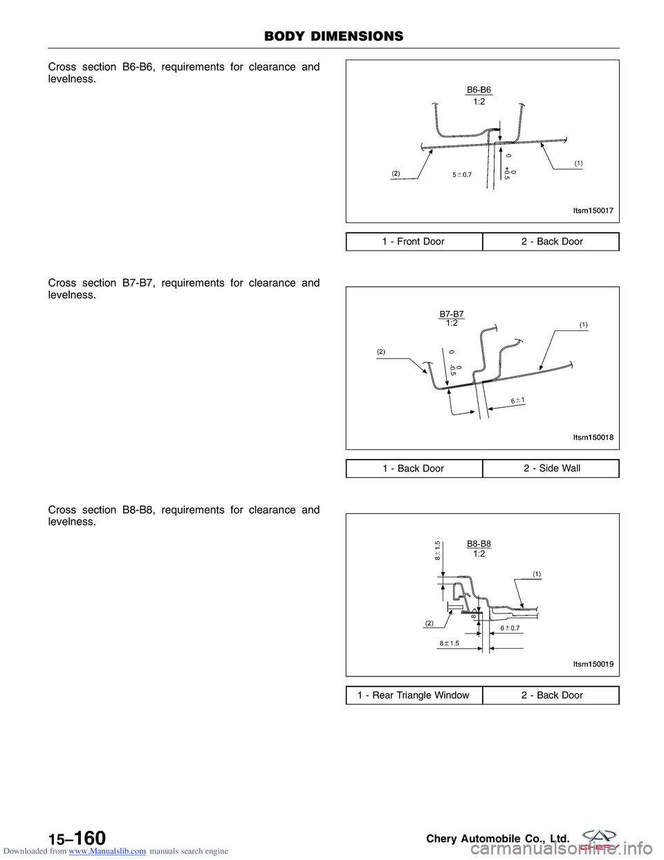
Downloaded from www.Manualslib.com manuals search engine Cross section B6-B6, requirements for clearance and
levelness.
Cross section B7-B7, requirements for clearance and
levelness.
Cross section B8-B8, requirements for clearance and
levelness.
1 - Front Door2 - Back Door
1 - Back Door 2 - Side Wall
1 - Rear Triangle Window 2 - Back Door
BODY DIMENSIONS
LTSM150017
LTSM150018
LTSM150019
15–160Chery Automobile Co., Ltd.
Page 1745 of 1903
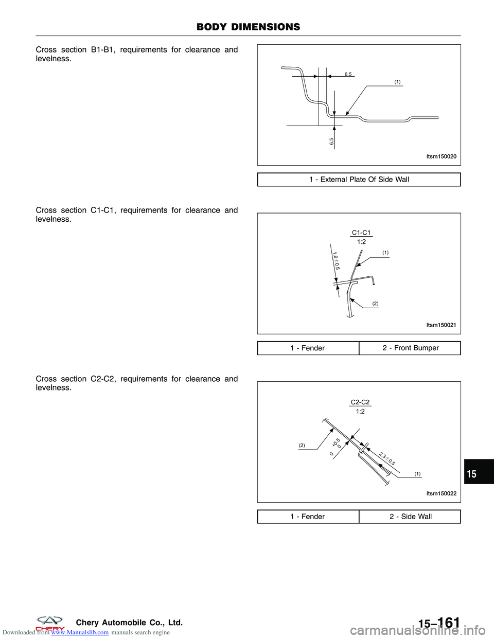
Downloaded from www.Manualslib.com manuals search engine Cross section B1-B1, requirements for clearance and
levelness.
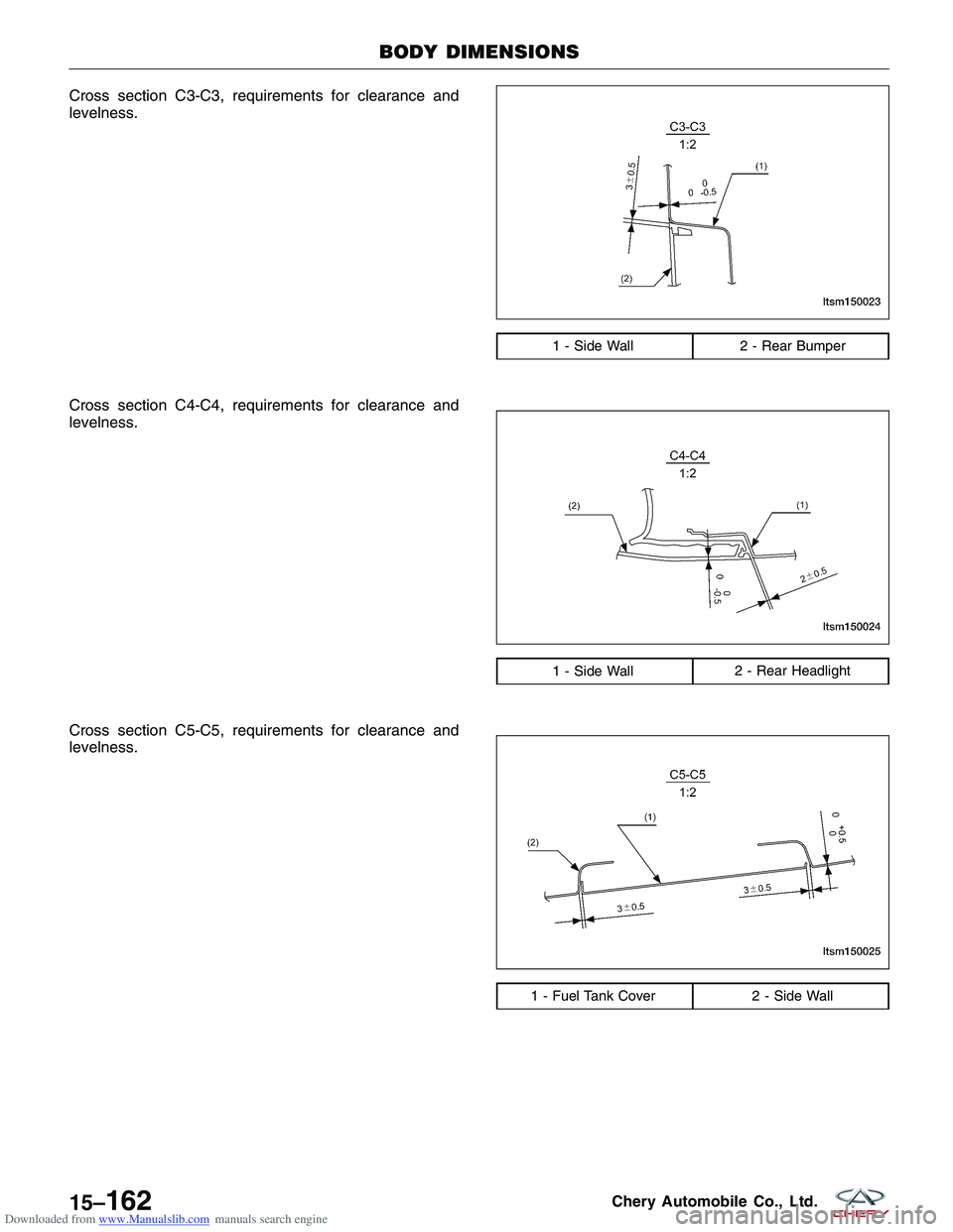
Cross section C1-C1, requirements for clearance and
levelness.
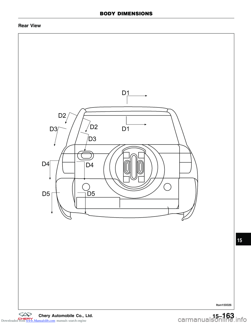
Cross section C2-C2, requirements for clearance and
levelness.
1 - External Plate Of Side Wall
1 - Fender2 - Front Bumper
1 - Fender 2 - Side Wall
BODY DIMENSIONS
LTSM150020
LTSM150021
LTSM150022
15
15–161Chery Automobile Co., Ltd.
Page 1746 of 1903
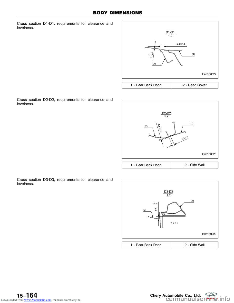
Downloaded from www.Manualslib.com manuals search engine Cross section C3-C3, requirements for clearance and
levelness.
Cross section C4-C4, requirements for clearance and
levelness.
Cross section C5-C5, requirements for clearance and
levelness.
1 - Side Wall2 - Rear Bumper
1 - Side Wall2 - Rear Headlight
1 - Fuel Tank Cover 2 - Side Wall
BODY DIMENSIONS
LTSM150023
LTSM150024
LTSM150025
15–162Chery Automobile Co., Ltd.
Page 1747 of 1903
Downloaded from www.Manualslib.com manuals search engine Rear View
BODY DIMENSIONS
LTSM150026
15
15–163Chery Automobile Co., Ltd.
Page 1748 of 1903
Downloaded from www.Manualslib.com manuals search engine Cross section D1-D1, requirements for clearance and
levelness.
Cross section D2-D2, requirements for clearance and
levelness.
Cross section D3-D3, requirements for clearance and
levelness.
1 - Rear Back Door2 - Head Cover
1 - Rear Back Door 2 - Side Wall
1 - Rear Back Door2 - Side Wall
BODY DIMENSIONS
LTSM150027
LTSM150028
LTSM150029
15–164Chery Automobile Co., Ltd.
Page 1749 of 1903
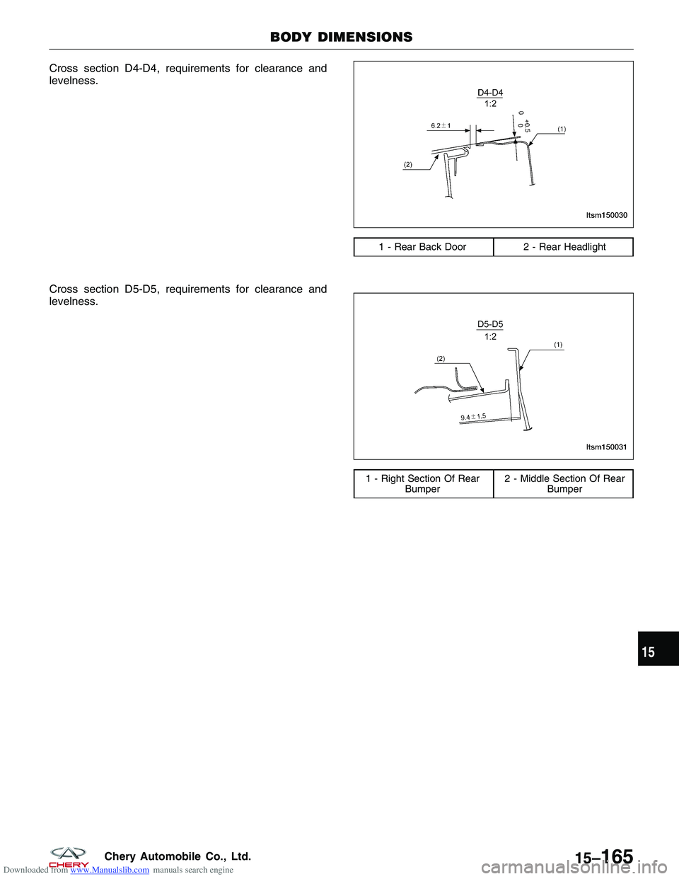
Downloaded from www.Manualslib.com manuals search engine Cross section D4-D4, requirements for clearance and
levelness.
Cross section D5-D5, requirements for clearance and
levelness.
1 - Rear Back Door2 - Rear Headlight
1 - Right Section Of Rear
Bumper 2 - Middle Section Of Rear
Bumper
BODY DIMENSIONS
LTSM150030
LTSM150031
15
15–165Chery Automobile Co., Ltd.
Page 1750 of 1903
Downloaded from www.Manualslib.com manuals search engine BUMPERS
Front Bumper
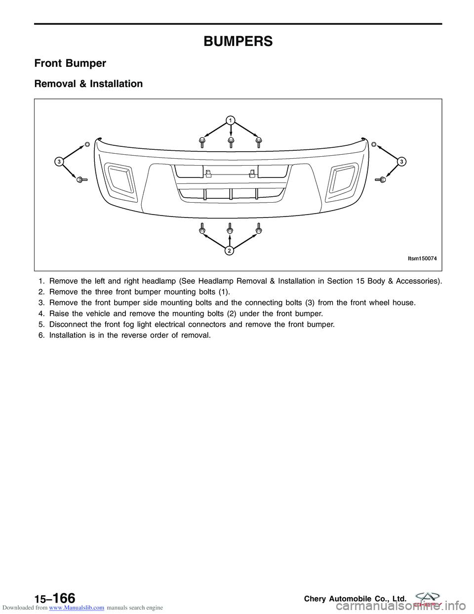
Removal & Installation
1. Remove the left and right headlamp (See Headlamp Removal & Installation in Section 15 Body & Accessories).
2. Remove the three front bumper mounting bolts (1).
3. Remove the front bumper side mounting bolts and the connecting bolts (3) from the front wheel house.
4. Raise the vehicle and remove the mounting bolts (2) under the front bumper.
5. Disconnect the front fog light electrical connectors and remove the front bumper.
6. Installation is in the reverse order of removal.
LTSM150074
15–166Chery Automobile Co., Ltd.
Trending: service reset, fuel type, torque, park assist, oil pressure, glove box, radio antenna
