CHEVROLET CAMARO 1967 1.G Chassis Workshop Manual
Manufacturer: CHEVROLET, Model Year: 1967, Model line: CAMARO, Model: CHEVROLET CAMARO 1967 1.GPages: 659, PDF Size: 114.24 MB
Page 151 of 659
CORVETTE BODY 1B-44
VIEW A
VIEW B
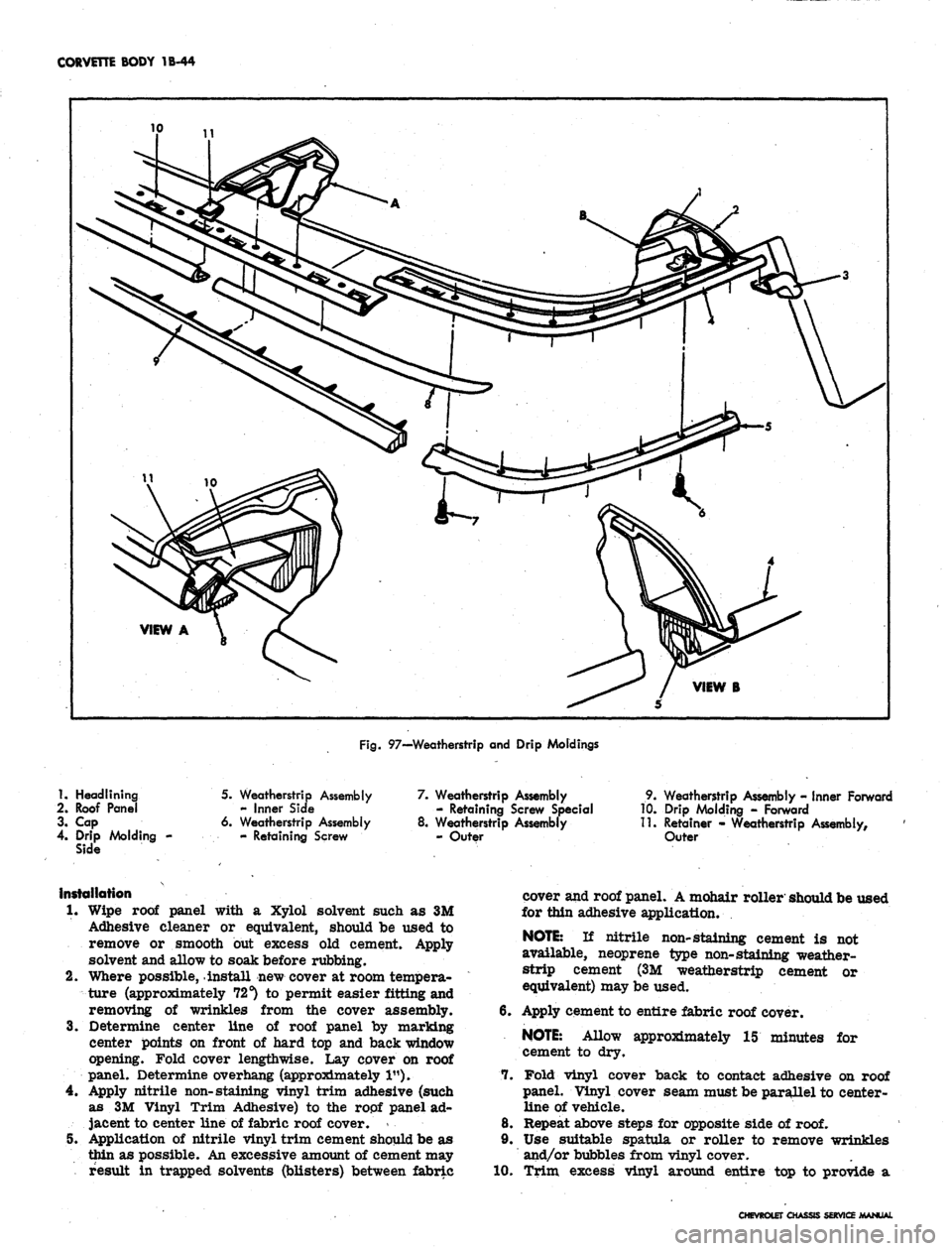
Fig.
97—Weatherstrip and Drip Moldings
1.
Headlining
2.
Roof Panel
3. Cap
4.
Drip Molding -
Side
5. Weatherstrip Assembly
- Inner Side
6. Weatherstrip Assembly
- Retaining Screw
7. Weatherstrip Assembly
- Retaining Screw Special
8. Weatherstrip Assembly
- Outer
9. Weatherstrip Assembly - Inner Forward
10.
Drip Molding - Forward
11.
Retainer - Weatherstrip Assembly,
Outer
Installation
1.
Wipe roof panel with a Xylol solvent such as 3M
Adhesive cleaner or equivalent, should be used to
remove or smooth but excess old cement. Apply
solvent and allow to soak before rubbing.
2.
Where possible, install new cover at room tempera-
ture (approximately 72 s) to permit easier fitting and
removing of wrinkles from the cover assembly.
3.
Determine center line of roof panel by marking
center points on front of hard top and back window
opening. Fold cover lengthwise. Lay cover on roof
panel. Determine overhang (approximately 1").
4.
Apply nitrile non-staining vinyl trim adhesive (such
as 3M Vinyl Trim Adhesive) to the ropf panel ad-
jacent to center line of fabric roof cover. *
5V Application of nitrile vinyl trim cement should be as
thin as possible. An excessive amount of cement may
result in trapped solvents (blisters) between fabric
cover and roof panel. A mohair roller should be used
for thin adhesive application.
NOTE:
If nitrile non-staining cement is not
available, neoprene type non-staining weather-
strip cement (3M weatherstrip cement or
equivalent) may be used.
6. Apply cement to entire fabric roof cover.
NOTE:
Allow approximately 15 minutes for
7.
cement to dry.
Fold vinyl cover back to contact adhesive on roof
panel. Vinyl cover seam must be parallel to center-
line of vehicle.
8. Repeat above steps for opposite side of
roof.
9. Use suitable spatula or roller to remove wrinkles
and/or bubbles from vinyl cover.
10.
Trim excess vinyl around entire top to provide a
CHEVROLET CHASSIS SERVICE MANUAL
Page 152 of 659
CORVETTE BODY 1B-45
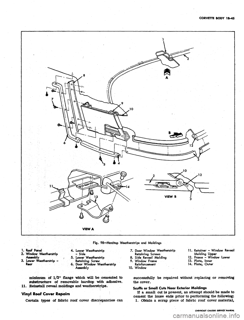
Fig.
98—Hardtop Weatherstrips and Moldings
1.
Roof Pane!
2.
Window Weatherstrip
Assembly
3. Lower Weatherstrip -
Rear
4.
Lower Weatherstrip
- Side
5. Lower Weatherstrip
Retaining Screw
6. Door Window Weatherstrip
Assembly
7. Door Window Weatherstrip
Retaining Screws
8. Side Reveal Molding
9. Window Frame
Reinforcement
10.
Window
11.
Retainer - Window Reveal
Molding Upper
12.
Frame - Window Lower
13.
Plate, Inner
14.
Plate, Outer
minimum of 1/2" flange which will be cemented to
substructure of removable hardtop with adhesive.
11.
Reinstall reveal moldings and weatherstrips.
Vinyl Roof Cover Repairs
Certain types of fabric roof cover discrepancies- can
successfully be repaired without replacing or removing
the cover.
Scuffs or Small Cuts Near Exterior Moldings
If a small cut is present, an attempt should be made to
cement the loose ends prior to performing the following:
1.
Obtain a scrap piece of fabric roof cover material,
CHEVROLET CHASSIS SERVICE MANUAL
Page 153 of 659
CORVETTE BODY 1B-46
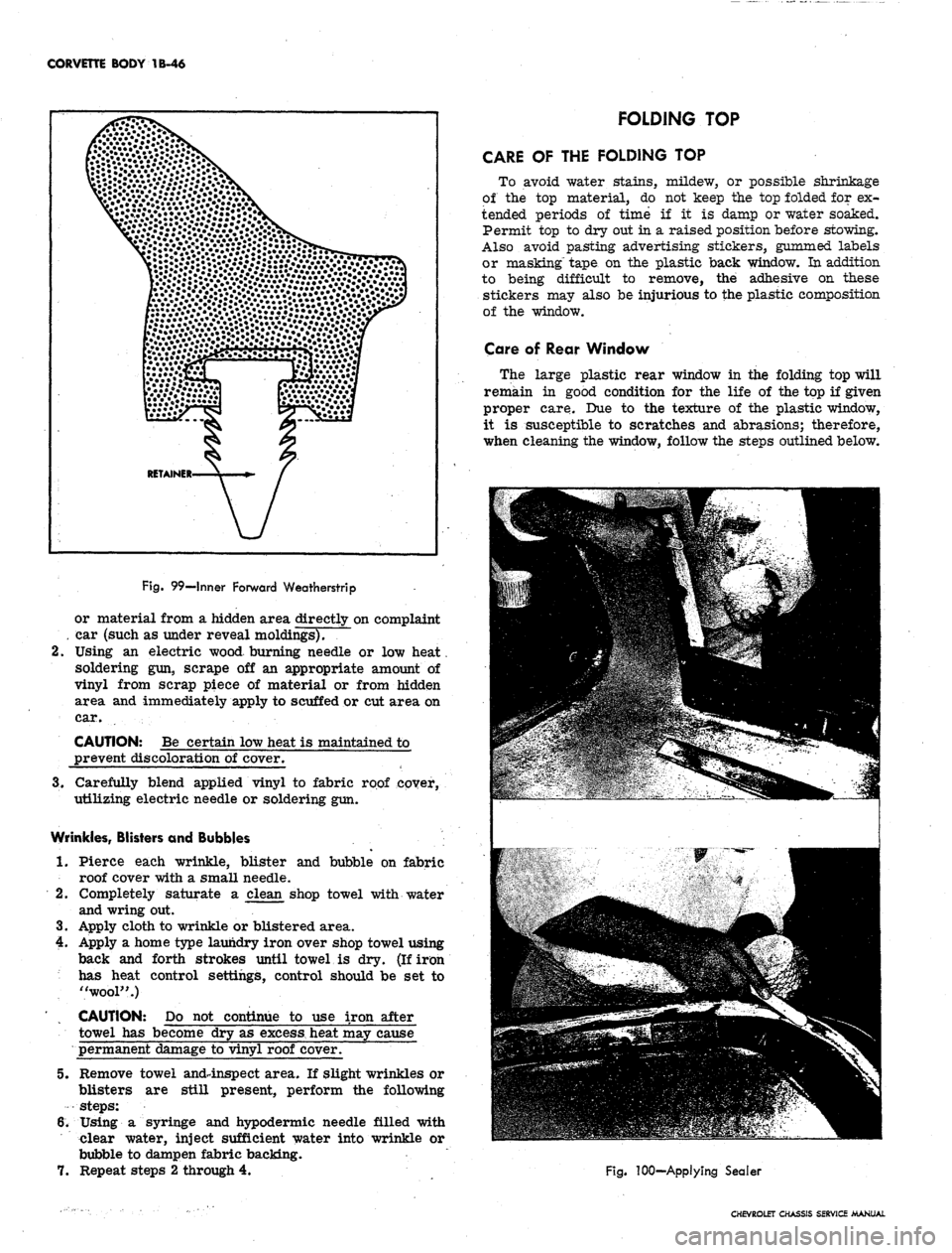
Fig.
99—Inner Forward Weatherstrip
or material from a hidden area directly on complaint
. car (such as under reveal moldings).
2.
Using an electric wood burning needle or low heat.
soldering gun, scrape off an appropriate amount of
vinyl from scrap piece of material or from hidden
area and immediately apply to scuffed or cut area on
car.
CAUTION: Be certain low heat is maintained to
prevent discoloration of cover.
3.
Carefully blend applied vinyl to fabric roof cover,
utilizing electric needle or soldering gun.
Wrinkles, Blisters and Bubbles
1.
Pierce each wrinkle, blister and bubble on fabric
roof cover with a small needle.
2.
Completely saturate a clean shop towel with water
and wring out.
3.
Apply cloth to wrinkle or blistered area.
4.
Apply a home type laundry iron over shop towel using
back and forth strokes until towel is dry. (If iron
has heat control settings, control should be set to
"wool".)
CAUTION: Do not continue to use iron after
towel has become dry as
excess,
heat may cause
permanent damage to vinyl roof cover.
5.
Remove towel and4nspect area. If slight wrinkles or
blisters are still present, perform the following
steps:
6. Using a syringe and hypodermic needle filled with
clear water, inject sufficient water into wrinkle or
bubble to dampen fabric backing.
7.
Repeat steps 2 through 4.
FOLDING TOP
CARE OF THE FOLDING TOP
To avoid water stains, mildew, or possible shrinkage
of the top material, do not keep the top folded for ex-
tended periods of time if it is damp or water soaked.
Permit top to dry out in a raised position before stowing.
Also avoid pasting advertising stickers, gummed labels
or masking" tape on the plastic back window. In addition
to being difficult to remove, the adhesive on these
stickers may also be injurious to the plastic composition
of the window.
Care of Rear Window
The large plastic rear window in the folding top will
remain in good condition for the life of the top if given
proper care. Due to the texture of the plastic window,
it is susceptible to scratches and abrasions; therefore,
when cleaning the window, follow the steps outlined below.
Fig.
100-Applying Sealer
CHEVROLET CHASSIS SERVICE MANUAL
Page 154 of 659
CORVETTE BODY
1B-47
REAR
BOW
ASSY.
VIEW
C
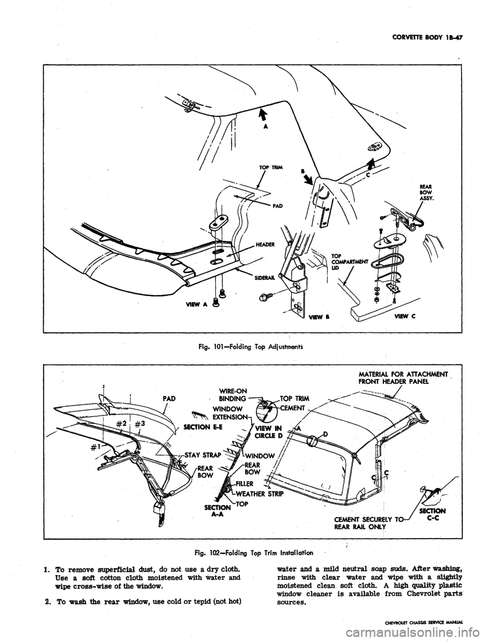
Fig.
101—Folding
Top
Adjustments
MATERIAL
FOR
ATTACHMENT
FRONT HEADER PANEL
PAD
WIRE-ON
BINDING
WINDOW
EXTENS
SECTION
E-E
AY STRAP
SECTION
A-A
CEMENT SECURELY
REAR RAIL ONLY
Fig.
102—Folding
Top
Trim Installation
1.
To
remove superficial dust,
do not use a
dry cloth.
Use
a
soft cotton cloth moistened with water
and
wipe cross-wise
of
the window.
2.
To
wash
the
rear window,
use
cold or tepid (not hot)
water
and a
mild neutral soap suds. After washing,
rinse with clear water
and
wipe with
a
slightly
moistened clean soft cloth.
A
high quality plastic
window cleaner
is
available from Chevrolet parts
sources.
CHEVROLET
Oi
SERVia
Page 155 of 659
CORVETTE BODY 1B-48
TOP
TRIM
TACKING
STRIP ^^^^^N^v^J
VIEW
A
WEATHERSTRIP
s
y
T\ TOP TRIM >.
HEADER PANEL
-
TOP PAD
^^
A
x. TOP
TRIM
V
Fig.
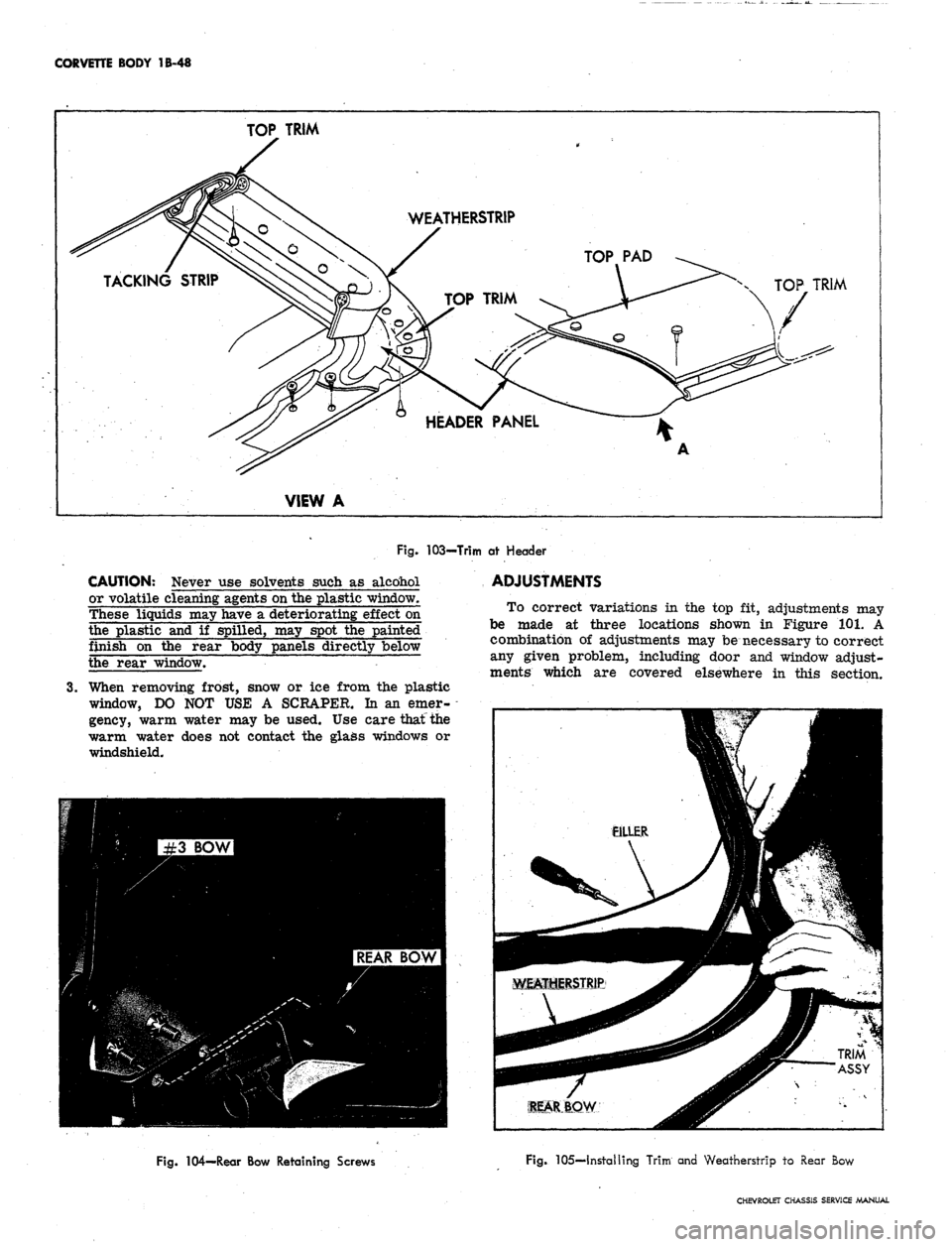
103-Trim at Header
CAUTION: Never use solvents such as alcohol
or volatile cleaning agents on the plastic window.
These liquids may have a deteriorating effect on
the plastic and if spilled, may spot the painted
finish on the rear body panels directly below
the rear window.
3.
When removing frost, snow or ice from the plastic
window, DO NOT USE A SCRAPER. In an emer-
gency, warm water may be used. Use care that the
warm water does not contact the glass windows or
windshield.
ADJUSTMENTS
To correct variations in the top fit, adjustments may
be made at three locations shown in Figure 101. A
combination of adjustments may be necessary to correct
any given problem, including door and window adjust-
ments which are covered elsewhere in this section.
Fig. 104—Rear Bow Retaining Screws
Fig. 105—Installing Trim and Weatherstrip to Rear Bow
CHEVROLET CHASSIS SERVICE MANUAL
Page 156 of 659
CORVETTE BODY 1B-49
Fig.
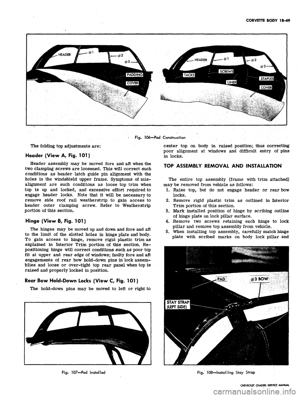
106-—Pad Construction
The folding top adjustments are:
Header (View A, Fig. 101)
Header assembly may be moved fore and aft when the
two clamping screws are loosened. This will correct such
conditions as header latch guide pin alignment with the
holes in the windshield upper frame. Symptoms of mis-
alignment are such conditions as loose top trim when
top is up and locked, and excessive effort required to
engage header locks. Note that it will be necessary to
remove side roof rail weatherstrip to gain access to
header outer clamping screw. Refer to Weatherstrip
portion of this section.
Hinge (View B, Fig. 101)
The hinges may be moved up and down and fore and aft
to the limit of the slotted holes in hinge plate and body.
To gain access to hinge, remove rigid plastic trim as
explained in Interior Trim portion of this section. Re-
positioning hinge will correct conditions such as poor top
fit at upper and rear edge of windows; faulty fore and aft
engagements of rear bow hold-down pins in lock assem-
blies and loose or oversight top rear panel when top is
raised and properly locked in position.
Rear Bow Hold-Down Locks (View C, Fig. 101)
The hold-down pins may be moved to left or right to
center top on body in raised position; thus correcting
poor alignment at windows and difficult entry of pins
in locks.
TOP ASSEMBLY REMOVAL AND INSTALLATION
The entire top assembly (frame with trim attached)
may be removed from vehicle as follows:
1.
Raise top, but do not engage header or rear bow
locks.
2.
Remove rigid plastic trim as outlined in Interior
Trim portion of this section.
3.
Mark installed position of hinge by scribing outline
of hinge plate on lock pillar surface.
4.
Remove two screws retaining each hinge to lock
pillar and remove top assembly from vehicle.
5.
When installing top assembly, carefully match hinge
plate with scribed marks on body lock pillar and
Fig.
107-Pad Installed
Fig.
108—Installing Stay Strap
CHEVROLET CHASSIS SERVICE MANUAL
Page 157 of 659
CORVETTE BODY 1B-50
WIRE-ON
BINDING
EXCESS
MATERIAL!
Fig.
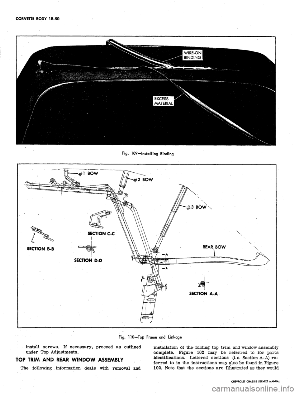
109—Installing Binding
\
L
SECTION B-B
SECTION A-A
Fig.
110—Top Frame and Linkage
install screws. If necessary, proceed as outlined
under Top Adjustments.
TOP TRIM AND REAR WINDOW ASSEMBLY
The following information deals with removal and
installation of the folding top trim and window assembly
complete. Figure 102 may be referred to for parts
identifications. Lettered sections (i.e. Section A-A) re-
ferred to in the instructions may also be found in Figure
102.
Note that the sections are illustrated as they would
CHEVROLET CHASSIS SERVICE MANUAL
Page 158 of 659
CORVETTE BODY
1B-51
Fig.
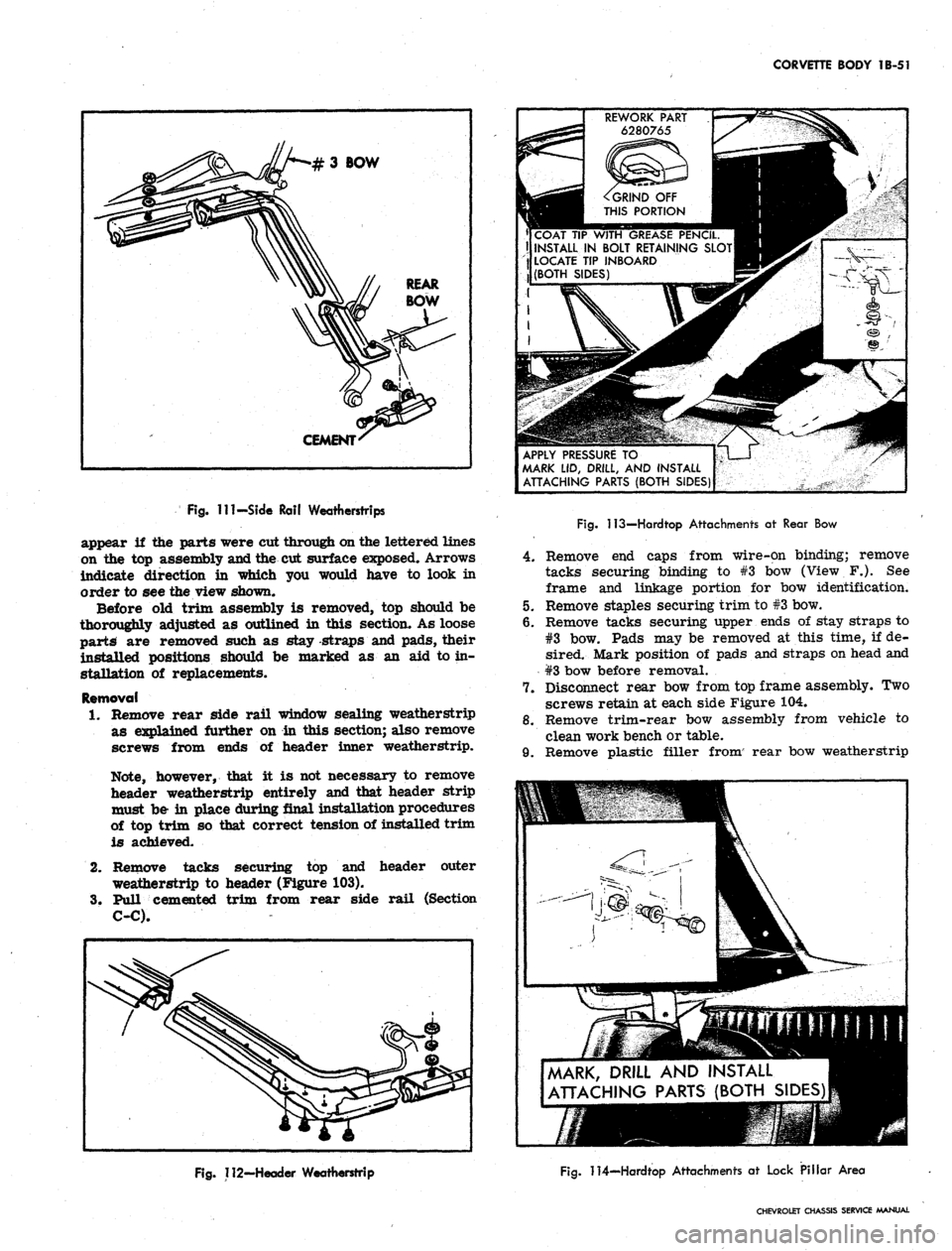
Ill-Side Rail Weatherstrips
appear
if the
parts were cut through on the lettered lines
on
the top
assembly and the
cut
surface exposed. Arrows
indicate direction
in
which
you
would have
to
look
in
order
to see
the view shown.
Before
old
trim assembly
is
removed,
top
should
be
thoroughly adjusted
as
outlined
in
this section.
As
loose
parts
are
removed such
as
stay -straps
and
pads, their
installed positions should
be
marked
as an aid to in-
stallation
of
replacements.
Removal
1.
Remove rear side rail window sealing weatherstrip
as explained further
on in
this section; also remove
screws from ends
of
header inner weatherstrip.
Note, however, that
it is not
necessary
to
remove
header weatherstrip entirely
and
that header strip
must
be- in
place during final installation procedures
of
top
trim
so
that correct tension
of
installed trim
is achieved.
2.
Remove tacks securing
top and
header outer
weatherstrip
to
header (Figure
103).
3.
Pull cemented trim from rear side rail (Section
C-C).
REWORK PART
6280765
^GRIND
OFF
THIS PORTION
COAT
TIP
WITH GREASE PENCIL.
II INSTALL
IN
BOLT RETAINING SLOT
LOCATE
TIP
INBOARD
(BOTH SIDES)
APPLY PRESSURE
TO
MARK
LID,
DRILL,
AND
INSTALL
ATTACHING PARTS (BOTH SIDES)
Fig.
113—Hardtop Attachments
at
Rear
Bow
4.
Remove end caps from wire-on binding; remove
tacks securing binding to #3 bow (View F.). See
frame and linkage portion for bow identification.
5.
Remove staples securing trim to #3 bow.
6. Remove tacks securing upper ends of stay straps to
#3 bow. Pads may be removed at this time, if de-
sired. Mark position of pads and straps on head and
#3 bow before removal.
7.
Disconnect rear bow from top frame assembly. Two
screws retain at each side Figure 104.
8. Remove trim-rear bow assembly from vehicle to
clean work bench or table.
9. Remove plastic filler from' rear bow weatherstrip
MARK, DRILL
AND
INSTALL
ATTACHING PARTS (BOTH SIDES)
Fig.
112-Header Weatherstrip
Fig.
114—Hardtop Attachments
at
Lock Pillar Area
CHEVROLET CHASSIS SERVICE MANUAL
Page 159 of 659
CORVETTE BODY 1B-52
and pull weatherstrip and trim from rear bow.
Section A-A shows installed position of these com-
ponents. Refer also to figure 105.
installation
1.
Find and mark center of header, #3 bow, rear bow
and leading and trailing edges of top trim. Align
these marks during installation and recheck their
alignment from time to time while installation is in
progress, especially during tacking or stapling.
2.
Assemble top trim and weatherstrip to rear bow,
referring to Section A-A and Figure 105. Note that
filler strip locks this assembly together and goes
in last. Align center marks.
3.
If new pads are required, install at this time, align-
ing with marks made when old pads were removed.
Figure 106 shows pad construction; Figure 107 shows
pad installed.
4.
Install top trim-rear bow assembly on top frame
with four screws removed at disassembly.
5.
Lock down rear bow in desired "top up" position.
Pull up stay straps and staple or tack to #3 bow
(fig. 108).
6. Pull leading edge of trim iip to header and align
center marks. Smooth out fabric and clamp, tack
or staple temporarily to header.
7.
Draw window extension up to #3 bow, aligning cen-
tering marks. Turn an ample amount of fabric under
and tack to #3 bow. Apply neoprene trim cement,
GM Part #3695016 or equivalent, to area shown in
View D of Figure 102. Follow directions on package.
8. Draw roof portion of trim over #3 bow, align marks
and tack on staple.
9. Trim off excess material and install wire-on binding
as shown in Figure 109 and View D of Figure 102.
Install binding caps.
10.
Remove temporary clamps or fastenings holding trim
to header.
11.
With header locked down, pull trim assembly up tight
and mark for final installation.
12.
Apply trim cement to header and rear side rail.
13.
Release header from windshield. Tack or staple trim
to header (fig. 103).
14.
Apply trim to rear side frame, previously cemented.
15.
Install weatherstrips which were removed at dis-
assembly and install retaining screws in header
weatherstrip.
16.
Make any adjustments necessary, following instruc-
tions listed under Folding Top—Adjustments.
FRAME AND LINKAGE
Figure 110 illustrates construction features of the
folding top frame and linkage. Various cross sections in
Figure 110 show the pivoting joints and their assembly.
If an operation is being performed which requires
removal of folding top trim, follow directions in this
section. The entire frame assembly may be removed and
replaced as a unit. Follow instructions for Folding Top
Trim and Rear Window Assembly and Top Assembly—
Removal and Installation.
The pivoting joints should be lubricated with light
machine oil once a year. Apply oil sparingly so as not
to stain top trim.
WEATHERSTRIP
Side Rail Weatherstrip
Figure 111 illustrates installation of side rail weather-
strip which acts to seal window opening. The weather-
strip is held in place by studs which are part of the
weatherstrip assembly, and by neoprene base cement
which is applied between weatherstrip and side rail
surface.
When replacing weatherstrip remove all rust, old
cement and foreign material from the surfaces to be
cemented, to assure successful bonding. Use only good
quality neoprene cement suitable for weatherstrip
application.
Header Weatherstrip
Weatherstrip assembly is retained to the header panel
by a combination of studs, sheet metal screws and special
fasteners as shown in Figure 112, along with neoprene
base weatherstrip cement.
Figure 99 shows' a cross section of weatherstrip taken
through a special fastener. To replace fastener, rotate
ninety degrees to align fastener head with slot. Follow
directions for cementing in the Side Rail Weatherstrip
instructions preceding this write up.
ADDING HARDTOP (ROOF PANEL ASSEMBLY)
An available roof panel assembly (hardtop) complete
can be added to convertible model Corvettes. The hard-
ware is included with the panel assembly.
Reworking of a plastic part (one for each side of the
roof panel) can be used as a marker for drilling of two
required holes in the folding top compartment lid* Hard-
ware is attached at four locations — two on the lid and
two (one each side) at the lock pillar area as follows:
1.
Rework two plastic retainers (#6280765) (used on
Chevrolet and Corvair door inner panels for trim
retention) as shown by Figure 113.
2.
Slide the reworked plastic retainers into the bolt re-
tainer slots on each side of the hardtop rear bow
(position plastic tip inboard).
3.
Mark the hardtop reveal molding at the approximate
location of the two plastic retainers,
4.
Mark the tips of the two plastic retainers with a
china marker pencil.
5.
Close the soft top compartment lid.
6. With aid of an ^assistant, position front of hardtop
onto header and lower onto vehicle. Do not fasten
latches at windshield header.
7.
Apply hand pressure at reveal molding marks.
8. Mark roof panel attachment hole location at each
lock pillar area (fig. 114).
9. With aid of an assistant, lift roof panel straight up
off body and set roof panel aside.
10.
Mark the drill position at the four china marks with
a center punch.
11.
Place a 2" x 4" board under the top compartment lid
to prevent drill damage to folding top material. Make
certain the compartment lid is securely locked
before drilling.
12.
Drill 1/8" pilot hole at the 4 marked locations.
CHEVROLET CHASSIS SERVICE MANUAL
Page 160 of 659
CORVETTE BODY 1B-53
13.
Drill 1/2" hole at pilot hole locations.
14..
Insert ferrules furnished for holes drilled in top
compartment lid. Crimp ferrule tabs.
15.
With aid of an assistant, place the hardtop onto the
vehicle and install attaching parts at all four loca-
tions.
Lock latches at windshield header.
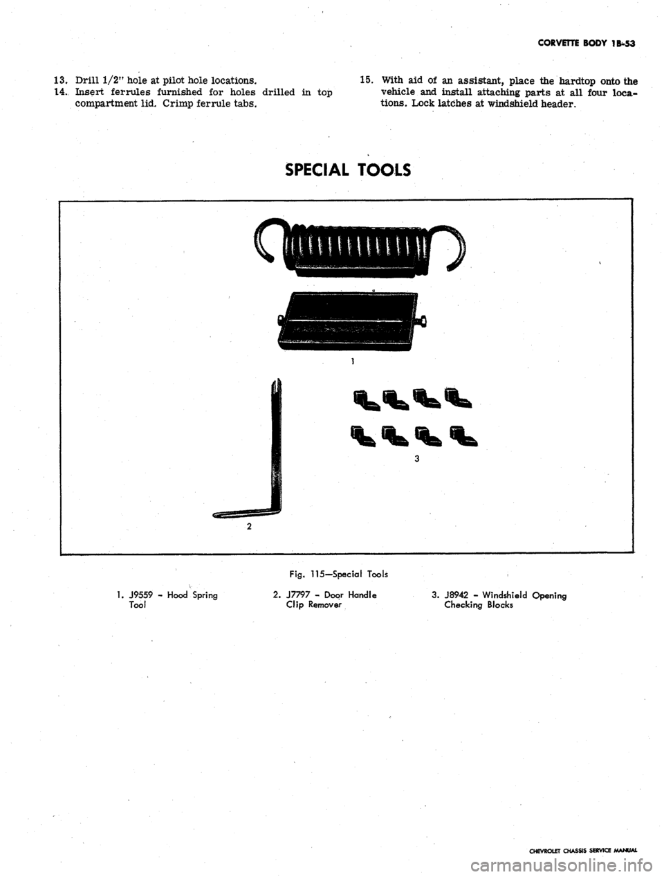
SPECIAL TOOLS
1.
J9559 - Hood Spring
Tool
Fig.
115-Special Tools
2.
J7797 - Door Handle
Clip Remover
3. J8942 - Windshield Opening
Checking Blocks
CHEVROLET CHASSIS SERVICE MANUAL