CHEVROLET CAMARO 1967 1.G Chassis Workshop Manual
Manufacturer: CHEVROLET, Model Year: 1967, Model line: CAMARO, Model: CHEVROLET CAMARO 1967 1.GPages: 659, PDF Size: 114.24 MB
Page 181 of 659
FRONT SUSPENSION 3-17
4.
Replace the wheel and tire.
5.
Lower the vehicle.
Chevy II
inspection
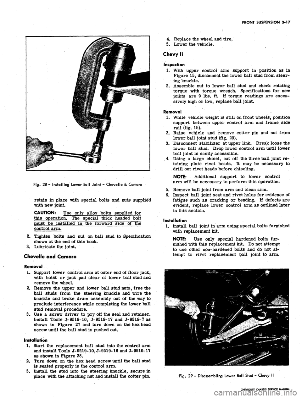
Fig.
28 - Installing Lower Ball Joint - Chevelle & Camaro
retain in place with special bolts and nuts supplied
with new joint.
CAUTION: Use only alloy bolts supplied for
this operation. The special thick headed bolt
must be installed in the forward side of the
control arm.
2.
Tighten bolts and nut on ball stud to Specification
shown at the end of this book.
3.
Lubricate the joint.
Chevelle and Camaro
Removal
1.
Support lower control arm at outer end of floor jack,
with hoist or jack pad clear of lower ball stud and
remove the wheel.
2.
Remove the upper and lower ball stud nuts, free the
ball studs from the steering knuckle and wire the
knuckle and brake drum assembly out of the way to
preclude interference while completing the lower ball
stud removal procedure.
3.
Use a screw driver to pry off the seal and retainer.
Install Tools J-9519-10, J-9519-17 and J-9519-7 as
shown in Figure 27 and turn down on the hex head
screw until the ball stud is pushed out.
Installation
1.
Start the replacement ball stud into the control arm
and install Tools J-9519-10, J^9519-16 and J-9519-17
as shown in Figure 28.
2.
Turn down on the hex head screw until the ball stud
is seated properly in the control arm.
3.
Install the stud into the steering knuckle, secure in
place with the attacking nut and install the cotter pin.
1.
With upper control arm support in position as in
Figure 15, disconnect the lower ball stud from steer-
ing knuckle.
2.
Assemble nut to lower ball stud and check rotating
torque with torque wrench. Specifications for new
joints are 9 lbs. ft. If torque readings are exces-
sively high or low, replace ball joint.
Removal
1.
While vehicle weight is still on front wheels, position
support between upper control arm and frame side
rail (fig. 15).
2.
Raise vehicle and remove cotter pin and nut from
lower ball joint stud (fig. 29).
3.
Disconnect stabilizer at upper link. Break loose the
lower ball stud. Drop lower control arm until lower
ball joint is easily accessible.
, 4. Using a large chisel, cut off the three ball joint re-
taining plate rivet heads. It may be necessary to
drill out rivet heads before chiseling.
NOTE: Additional support to lower control
arm will be necessary to perform this operation.
5.
Remove ball joint from arm and clean arm.
6. Inspect ball joint seat and rivet holes for evidence of
fatigue such as cracking or bending. If defects are
evident, replace lower control arm as outlined later
in this section.
Installation
1.
Install ball joint in arm using special bolts furnished
with replacement kit.
NOTE: Use only special hardened bolts fur-
nished with this replacement kit. Do not attempt
to use other non-hardened bolts and do not at-
tempt to rivet replacement ball joint to arm.
Fig.
29- Disassembling Lower Ball Stud - Chevy
CHEVROLET CHASSIS SERVICE MANUAL
Page 182 of 659
FRONT SUSPENSION 3-18
CHEVROLET
CHEVELLE
CAMARO (TYPICAL)
CHEVY U
LOWER CONTROL ARM
CORVETTE
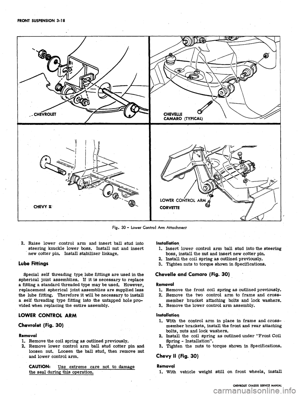
Fig.
30 - Lower Control Arm Attachment
2.
Raise lower control arm and insert ball stud into
steering knuckle lower boss. Install nut and insert
new cotter pin. Install stabilizer linkage.
Lube Fittings
Special self threading type lube fittings are used in the
spherical joint assemblies. If it is necessary to replace
a fitting a standard threaded type may be used. However,
replacement spherical joint assemblies are supplied less
the lube fitting. Therefore it will be necessary to install
a self threading type fitting into the untapped hole pro-
vided when replacing the entire assembly.
LOWER CONTROL ARM
Chevrolet (Fig. 30)
Removal
1.
Remove the coil spring as outlined previously.
2.
Remove lower control arm ball stud cotter pin and
loosen nut. Loosen the ball stud, then remove nut
and lower control arm.
CAUTION: Use extreme care not to damage
the seal during this operation.
Installation
1.
Insert lower control arm ball stud into the steering
boss,
install the nut and insert new cotter pin.
2.
Install the coil spring as outlined previously.
3.
Tighten nuts to torque shown in Specifications.
Chevelle and Camaro (Fig. 30)
Removal
1.
Remove the front coil spring as outlined previously.
2;
Remove the two control arm to frame and cross-
member bracket attaching bolts and lock washers.
3.
Remove the lower control arm assembly.
Installation
1.
With the control arm in place in frame and cross-
member brackets, install the front and rear attaching
bolts,
nuts and lock washers.
2.
Install the coil spring as outlined under "Front Coil
Spring - Installation".
3.
Tighten the nuts to torque shown in Specifications.
Chevy II (Fig. 30)
Removal
1.
With vehicle weight still on front wheels, install
CHEVROLET CHASSIS SERVICE MANUAL
Page 183 of 659
FRONT
SUSPENSION 3-19
spacer between upper control arm and frame side
rail (fig. 15). Raise vehicle.
2.
Remove lower control arm ball stud cotter pin and
loosen hut.
3.
Loosen ball stud and remove nut. Drop lower control
arm.
CAUTION: Use extreme care not to damage
the seal during this operation? "~~~~
4.
Mark lower control arm pivot bolt and adjusting cam
for realignment. Remove nut securing pivot bolt and
cam assembly. Remove pivot bolt and cam. Remove
lower control arm.
Installation
1.
Insert lower control arm into its support bracket,
index pivot bolt and cams, pivot nut and tighten to
torque shown in Specifications.
2.
Raise lower control arm ball stud into steering
knuckle boss and install nut. Tighten nut to torque
shown in Specifications and insert new cotter pin.
3.
Lower vehicle and remove upper control arm to
frame support.
Corvette (Fig. 30)
Removal
1.
Remove the front coil spring as outlined under
"Front Spring, Removal".
2.
Remove the two front cross shaft to frame attaching
bolts and lock washers and the rear frame attaching
nut and lock washer.
3.
Remove the lower control arm assembly from the
vehicle.
THRUST
BEARING
FLAT
WASHER
REMOVAL
J-21878
J-21830-7
J-21058-8
J-21474-8
/J-21058-15
J-9519-17
J-21830-7
INSTALLATION
J-21058-15
J-2/878 FLAT
REMOVAL
BUSHING
INSTALLATION
BUSHING
CONTROL
J22175
THRUST
ARM
^ ,. / BEARING
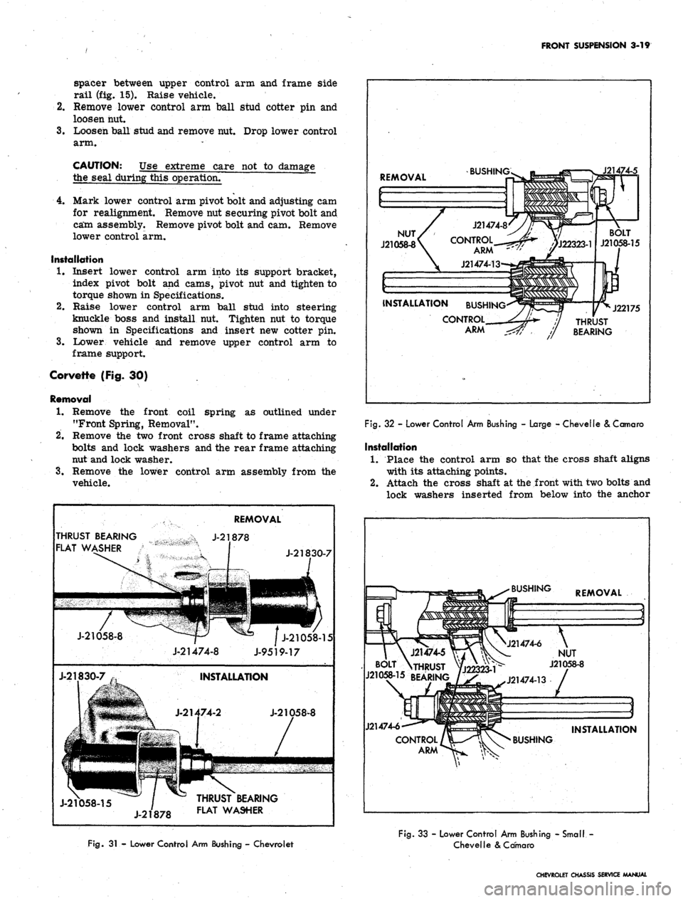
Fig.
32 - Lower Control Arm Bushing - Large - Chevelle & Comoro
Installation
1.
Place the control arm so that the cross shaft aligns
with its attaching points.
2.
Attach the cross shaft at the front with two bolts and
lock washers inserted from below into the anchor
BUSHING
REMOVAL
J21474-6
J21474-5
TTf\ ft^\- NUT
BOLT
VHRUST
^22323-^ J21058"8
J21058-15
REARING, / ^_ ^
J21474-13
INSTALLATION
Fig.
31 - Lower Control Arm Bushing - Chevrolet
Fig.
33 - Lower Control Arm Bushing - Small -
Chevelle
& Comoro
CHEVROLET CHASSIS SERVICE MANUAL
Page 184 of 659
FRONT SUSPENSION 3-20
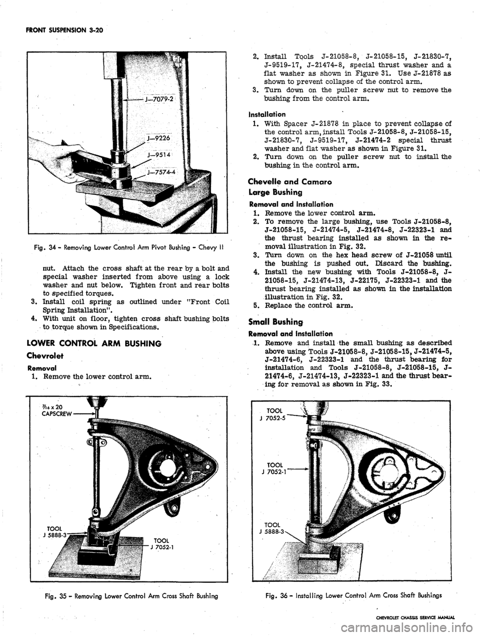
Fig.
34 - Removing Lower Control Arm Pivot Bushing - Chevy II
nut. Attach the cross shaft at the rear by a bolt and
special washer inserted from above using a lock
washer and nut below. Tighten front and rear bolts
to specified torques.
3.
Install coil spring as outlined under "Front Coil
Spring Installation".
4.
With unit on floor, tighten cross shaft bushing bolts
to torque shown in Specifications.
LOWER CONTROL ARM BUSHING
Chevrolet
Removal
1.
Remove the lower control arm.
2.
Install Tools J-21058-8, J-21058-15, J-21830-7,
J-9519-17, J-21474-8, special thrust washer and a
flat washer as shown in Figure
31.
Use J-21878 as
shown to prevent collapse of the control arm.
3.
Turn down on the puller screw nut to remove the
bushing from the control arm.
Installation
1.
With Spacer J-21878 in place to prevent collapse of
the control arm, install Tools J-21058-8, J-21058-15,
J-21830-7, J-9519-17, J-21474-2 special thrust
washer and flat washer as shown in Figure 31,
2.
Turn down on the puller screw nut to install the
bushing in the control arm.
Chevelle and Camaro
Large Bushing
Removal and Installation
1.
Remove the lower control arm.
2.
To remove the large bushing, use Tools J-21058-8,
J-21058-15, J-21474-5, J-21474-8, J-22323-1 and
the thrust bearing installed as shown in the re-
moval illustration in Fig. 32.
3.
Turn down on the hex head screw of J-21058 until
the bushing is pushed out. Discard the bushing.
4.
Install the new bushing with Tools J-21058-8, J-
21058-15,
J-21474-13, J-22175, J-22323-1 and the
thrust bearing installed as shown in the installation
illustration in Fig. 32.
5.
Replace the control arm.
Small Bushing
Removal and Installation
1.
Remove and install the small bushing as described
above using Tools J-21058-8, J-21058-15, J-21474-5,
J-21474-6, J-22323-1 and the thrust bearing for
installation and Tools J-21058-8, J-21058-15, J-
21474-6, J-21474-13, J-22323-1 and tiie thrust bear-
ing for removal as shown in Fig. 33.
7/\6 x 20
CAPSCREW
TOOL
J 5888-3
TOOL
J 7052-5
TOOL
J 7052-1
TOOL
J 5888-3-
Fig.
35 - Removing Lower Control Arm Cross Shaft Bushing
Fig.
36 - Installing Lower Control Arm Cross Shaft Bushings
CHEVROLET CHASSIS SERVICE MANUAL
Page 185 of 659
FRONT SUSPENSION 3-21
Chevy II
Removal
1.
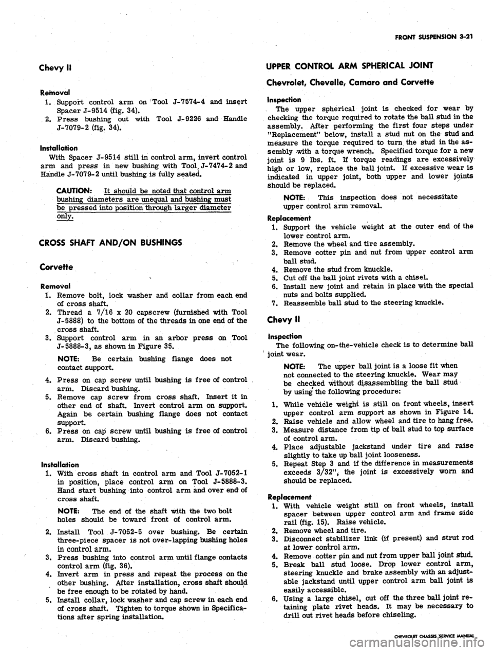
Support control arm on Tool J-7 574-4 and insert
Spacer J-9514 (fig. 34).
2,
Press bushing out with Tool J-9226 and Handle
J-7079-2 (fig. 34).
Installation
With Spacer J-9514 still in control arm, invert control
arm and press in new bushing with Tool, J-7474-2 and
Handle J-7079-2 until bushing is fully seated.
CAUTION: It should be noted that control arm
bushing diameters are unequal and bushing must
be pressed into position through larger diameter
only.
CROSS SHAFT AND/ON BUSHINGS
Corvette
Removal
1.
Remove bolt, lock washer and collar from each end
of cross shaft.
2.
Thread a 7/16 x 20 capscrew (furnished with Tool
J-5888) to the bottom of the threads in one end of the
cross shaft.
3.
Support control arm in an arbor press on Tool
J-5888-3,
as shown in Figure 35.
NOTE:
Be certain bushing flange does not
contact support.
4.
Press on cap screw until bushing is free of control
arm. Discard bushing.
5. Remove cap screw from cross shaft. Insert it in
other end of shaft. Invert control arm on support.
Again be certain bushing flange does not contact
support.
6. Press on cap screw until bushing is free of control
arm. Discard bushing.
Installation
1.
With cross shaft in control arm and Tool J-7052-1
in position, place control arm on Tool J-5888-3.
Hand start bushing into control arm and over end of
cross shaft.
NOTE:
The end of the shaft with the two bolt
holes should be toward front of control arm.
2.
Install Tool J-7052-5 over bushing. Be certain
three-piece spacer is not over-lapping bushing holes
in control arm.
3.
Press bushing into control arm until flange contacts
control arm (fig. 36).
4.
Invert arm in press and repeat the process on the
other bushing. After installation, cross shaft should
be free enough to be rotated by hand.
5. Install collar, lock washer and cap screw in each end
of cross shaft. Tighten to torque shown in Specifica-
tions after spring installation.
UPPER CONTROL ARM SPHERICAL JOINT
Chevrolet, Chevelle, Comoro and Corvette
Inspection
The upper spherical joint is checked for wear by
checking the torque required to rotate the ball stud in the
assembly. After performing the first four steps under
"Replacement" below, install a stud nut on the stud and
measure the torque required to turn the stud in the as-
sembly with a torque wrench. Specified torque for a new
joint is 9 lbs. ft. If torque readings are excessively
high or low, replace the ball joint. If excessive wear is
indicated in upper joint, both upper and lower joints
should be replaced.
NOTE:
This inspection does not necessitate
upper control arm removal.
Replacement
1.
Support the vehicle weight at the outer end of the
lower control arm.
2.
Remove the wheel and tire assembly.
3.
Remove cotter pin and nut from upper control arm
ball stud.
4.
Remove the stud from knuckle.
5. Cut off the ball joint rivets with a chisel.
6. Install new joint and retain in place with the special
nuts and bolts supplied.
7. Reassemble ball stud to the steering knuckle.
Chevy II
Inspection
The following on-the-vehicle check is to determine ball
joint wear.
NOTE:
The upper ball joint is a loose fit when
not connected to the steering knuckle. Wear may
be checked without disassembling the ball stud
by
using'
the following procedure:
1.
While vehicle weight is still on front wheels, insert
upper control arm support as shown in Figure 14.
2.
Raise vehicle and allow wheel and tire to hang free.
3.
Measure distance from tip of ball stud to top surface
of control arm.
4.
Place adjustable jackstand under tire and raise
slightly to take up ball joint looseness.
5. Repeat Step 3 and if the difference in measurements
exceeds 3/32", the joint is excessively worn and
should be replaced.
Replacement
1.
With vehicle weight still on front wheels, install
spacer between upper control arm and frame side
rail (fig. 15). Raise vehicle.
2.
Remove wheel and tire.
3.
Disconnect stabilizer link (if present) and strut rod
at lower control arm.
4.
Remove cotter pin and nut from upper ball joint stud.
5. Break ball stud loose. Drop lower control arm,
steering knuckle and brake assembly with an adjust-
able jackstand until upper control arm ball joint is
easily accessible.
6. Using a large chisel, cut off the three ball joint re-
taining plate rivet heads. It may be necessary to
drill out rivet heads before chiseling.
CHEVROLET CHASSIS SERVICE MANUAL
Page 186 of 659
FRONT SUSPENSION
3-22
CHEVROLET
s-L 1 \
TYPICAL
OF
-^-x ^K CORVETTE, CHEVELLE AND CAMARO
CHEVY n
Rg.
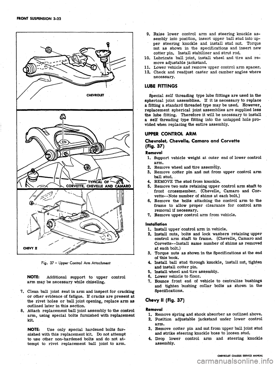
37 - Upper Control Arm Attachment
NOTE:
Additional support to upper control
arm may be necessary while chiseling.
7. Clean ball joint seat in arm and inspect for cracking
or other evidence of fatigue. If cracks are present at
the rivet holes or ball joint opening, replace arm as
outlined later in this section.
8. Attach replacement ball joint assembly to the control
arm, using special bolts furnished with replacement
kit.
NOTE:
Use only special hardened bolts fur-
nished with this replacement kit. Do not attempt
to use other non-hardened bolts and do not at-
tempt to rivet replacement ball joint to arm.
9. Raise lower control arm and steering knuckle as-
sembly into position, insert upper ball stud into up-
per steering knuckle and install stud nut. Torque
nut as shown in the specifications and insert new
cotter pin. Install stabilizer and strut rod.
10.
Lubricate ball joint, install wheel and tire and re-
move adjustable jackstand.
11.
Lower vehicle and remove upper control arm spacer.
12.
Check and readjust caster and camber angles where
necessary.
LUBE FITTINGS
Special self threading type lube fittings are used in the
spherical joint assemblies. If it is necessary to replace
a fitting a standard threaded type may be used. However,
replacement spherical joint assemblies are supplied less
the lube fitting. Therefore it will be necessary to install
a self threading type fitting into the untapped hole pro-
vided when replacing the entire assembly.
UPPER CONTROL ARM
Chevrolet, Chevelle, Camaro and Corvette
(Fig.
37)
Removal
1.
Support vehicle weight at outer end of lower control
arm.
2.
Remove wheel and tire assembly.
3.
Remove cotter pin and nut from upper control arm
ball stud. ,
4.
REMOVE The stud from knuckle.
5. Remove two nuts retaining upper control arm shaft to
front crossmember. (Chevelle, Camaro and Cor-
vette—Note number of shims at each bolt.)
6. Remove the bolts attaching the control arm to the
frame to allow proper clearance for control arm
removal if necessary.
7. Remove upper control arm from vehicle.
Installation
1.
Install upper control arm in vehicle.
2.
Install nuts, bolts and lock washers retaining upper
control arm shaft to frame. (Chevelle, Camaro and
Corvette—Install same number of shims as removed
at each bolt.)
3.
Torque nuts as shown in the Specifications at the end
of this book.
4.
Install ball stud through knuckle, install nut, tighten
and install cotter pin.
5. Install wheel and tire assembly.
6. Lower vehicle to floor.
7. Bounce front end of vehicle to centralize bushings
and tighten bushing collar bolts as shown in the
Specifications.
Chevy II (Fig. 37)
Removal
1.
Remove spring and shock absorber as outlined above.
2.
Position adjustable jackstand under lower control
arm.
3.
Remove cotter pin and nut from upper ball joint stud
and strike steering knuckle boss to loosen stud.
4.
Drop lower control arm and steering knuckle
assembly.
CHEVROLET CHASSIS SERVICE MANUAL
Page 187 of 659
FRONT SUSPENSION 3-23
CHEVROLET
J-7052-2
CAMARO
& CHEVELLE
J-21482
CHEVROLET
J-7052-2
CAMARO
& CHEVELLE
J-21482
Fig.
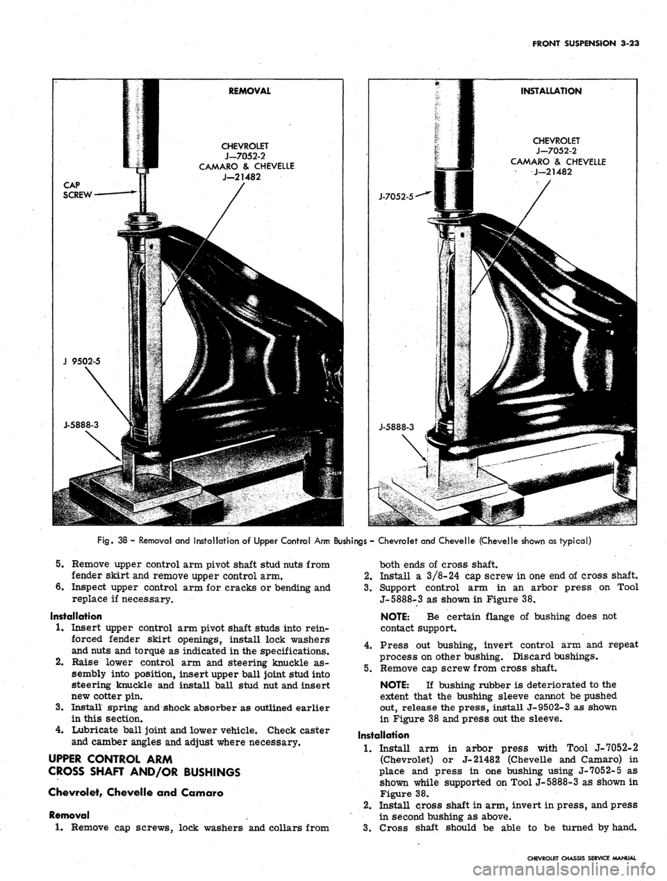
38 - Removal and Installation of Upper Control Arm Bushings - Chevrolet and Chevelle (Chevelle shown as typical)
5.
Remove upper control arm pivot shaft stud nuts from
fender skirt and remove upper control arm.
6. Inspect upper control arm for cracks or bending and
replace if necessary.
Installation
1.
Insert upper control arm pivot shaft studs into rein-
forced fender skirt openings, install lock washers
and nuts and torque as indicated in the specifications.
Raise lower control arm and steering knuckle as-
sembly into position, insert upper ball joint stud into
steering knuckle and install ball stud nut and insert
new cotter pin.
Install spring and shock absorber as outlined earlier
in this section.
Lubricate ball joint and lower vehicle. Check caster
and camber angles and adjust where necessary.
UPPER CONTROL ARM
CROSS SHAFT AND/OR BUSHINGS
Chevrolet, Chevelle and Camaro
Removal
1.
Remove cap screws, lock washers and collars from
2.
3.
4.
both ends of cross shaft.
2.
Install a 3/8-24 cap screw in one end of cross shaft,
3.
Support control arm in an arbor press on Tool
J-5888-3 as shown in Figure 38.
NOTE: Be certain flange of bushing does not
contact support.
4.
Press out bushing, invert control arm and repeat
process on other bushing. Discard bushings.
5.
Remove cap screw from cross shaft.
NOTE: If bushing rubber is deteriorated to the
extent that the bushing sleeve cannot be pushed
out, release the press, install J-9502-3 as shown
in Figure 38 and press out the sleeve.
Installation
1.
Install arm in arbor press with Tool J-7052-2
(Chevrolet) or J-21482 (Chevelle and Camaro) in
place and press in one bushing using J-7052-5 as
shown while supported on Tool j-5888-3 as shown in
Figure 38.
2.
Install cross shaft in arm, invert in press, and press
in second bushing as above.
3.
Cross shaft should be able to be turned by hand.
CHEVROLET CHASSIS SERVICE MANUAL
Page 188 of 659
FRONT SUSPENSION 3-24
Fig.
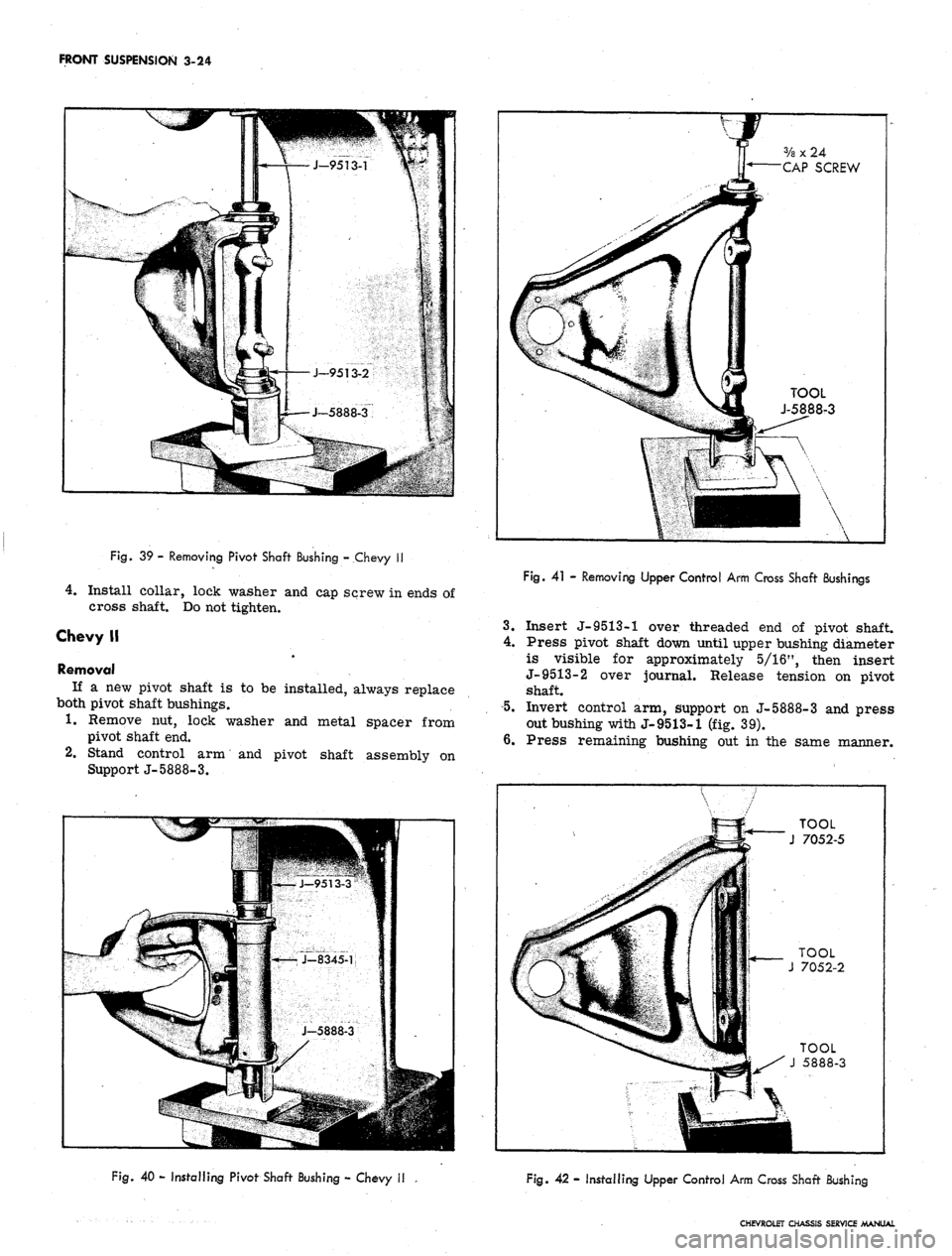
39 - Removing Pivot Shaft Bushing - Chevy II
4.
Install collar, lock washer and cap screw in ends of
cross shaft. Do not tighten.
Chevy II
Removal
If a new pivot shaft is to be installed, always replace
both pivot shaft bushings.
1.
Remove nut, lock washer and metal spacer from
pivot shaft end.
2.
Stand control arm and pivot shaft assembly on
Support J-5888-3.
V
f
ff 3/a x 24
y* CAP SCREW
k
a
4f TOOL
i J-5888-3
••
Fig.
41 - Removing Upper Control Arm Cross Shaft Bushings
3.
Insert J-9513-1 over threaded end of pivot shaft.
4.
Press pivot shaft down until upper bushing diameter
is visible for approximately 5/16", then insert
J-9513-2 over journal. Release tension on pivot
shaft.
5.
Invert control arm, support on J-5888-3 and press
out bushing with J-9513-1 (fig. 39).
6. Press remaining bushing out in the same manner.
TOOL
J 7052-5
Fig.
40 - Installing Pivot Shaft Bushing - Chevy II
Fig. 42 - Installing Upper Control Arm Cross Shaft Bushing
CHEVROLET CHASSIS SERVICE MANUAL
Page 189 of 659
FRONT SUSPENSION 3-25
Installation
1.
Insert new bushing in control arm and over pivot
shaft.
2.
Support arm on J-5888-3 and insert Spacer J-
8345-1.
5.
Press bushing into place with Installer J-9513-3
(fig. 40).
Invert arm and press remaining bushing in place with
J-9513-3.
Install bushing spacers, lock washers and nuts
to pivot shaft ends. Torque as indicated in
Specifications.
NOTE:
Pivot shaft bolts must be in horizontal
position (toward center line of vehicle) before
torquing nuts.
Corvette
Removal
1.
Remove cap screws, lock washers and collars from
both ends of cross shaft.
2.
Install a 3/8-24 cap screw (furnished with Tool
J- 5888) in one end of cross shaft.
3.
Support control arm in an arbor press on Tool
J-5888-3 as shown in Figure 41.
NOTE:
Be certain flange of bushing does not
contact support.
4.
Press out bushing, invert control arm and repeat
process on other bushing. Discard bushings.
5. Remove cap screw from cross shaft.
Installation
1.
Install arm in arbor press with Tool J-7052-2 in
place and press in one bushing while supported on
Tool J-5888-3 as shown in Figure 42.
2.
Install cross shaft in arm, invert in press, and press
in second bushing as above.
3.
Cross shaft should be able to be turned by hand.
4.
Install collar, lock washer and cap screw in ends of
cross shaft. Do not tighten.
CHEVROLET CHASSIS SERVICE MANUAL
Page 190 of 659
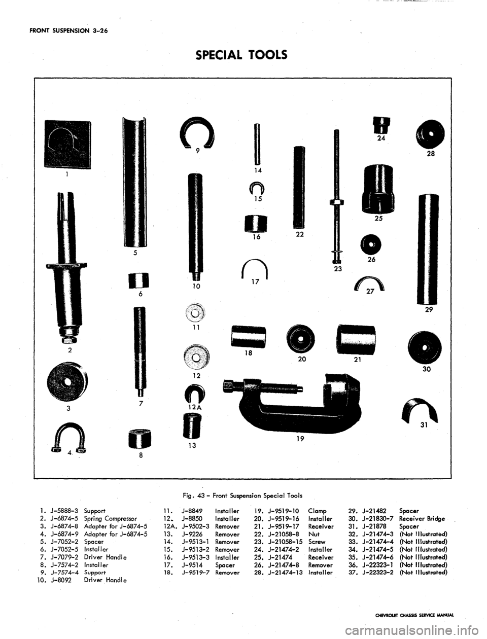
FRONT SUSPENSION 3-26
SPECIAL TOOLS
1.
J-5888-3
2.
J-6874-5
3. J-6874-8
4. J-6874-9
5. J-7052-2
6. J-7052-5
7. J-7079-2
8. J-7574-2
9. J-7574-4
0. J-8092
Support-
Spring Compressor
Adapter for J-6874-5
Adapter for J-6874-5
Spacer
Installer
Driver Handle
Installer
Support
Driver Handle
11.
12.
12A.
13.
14.
15.
16.
17.
18.
Fig.
43-
J-8849
J-8850
J-9502-3
J-9226
J-9513-1
J-9513-2
J-9513-3
J-9514
J-9519-7
Front Suspension Special Tools
Installer
Installer
Remover
Remover
Remover
Remover
Installer
Spacer
Remover
19.
J-9519-10
20.
J-9519-16
21.
J-9519-17
22.
J-21058-8
23.
J-21058-15
24.
J-21474-2
25.
J-21474
26.
J-21474-8
28.
J-21474-13
Clamp
Installer
Receiver
Nut
Screw
Installer
Receiver
Remover
Installer
29.
J-21482
30.
J-21830-7
31.
J-21878
32.
J-21474-3
33.
J-21474-4
34.
J-21474-5
35.
J-21474-6
36.
J-22323-1
37.
J-22323-2
Spacer
Receiver Bridge
Spacer
(Not Illustrated)
(Not Illustrated)
(Not Illustrated)
(Not illustrated)
(Not Illustrated)
(Not Illustrated)
CHEVROLET CHASSIS SERVICE MANUAL