DATSUN 210 1979 Service Manual
Manufacturer: DATSUN, Model Year: 1979, Model line: 210, Model: DATSUN 210 1979Pages: 548, PDF Size: 28.66 MB
Page 351 of 548
Rear
Axle
Rear
Suspension
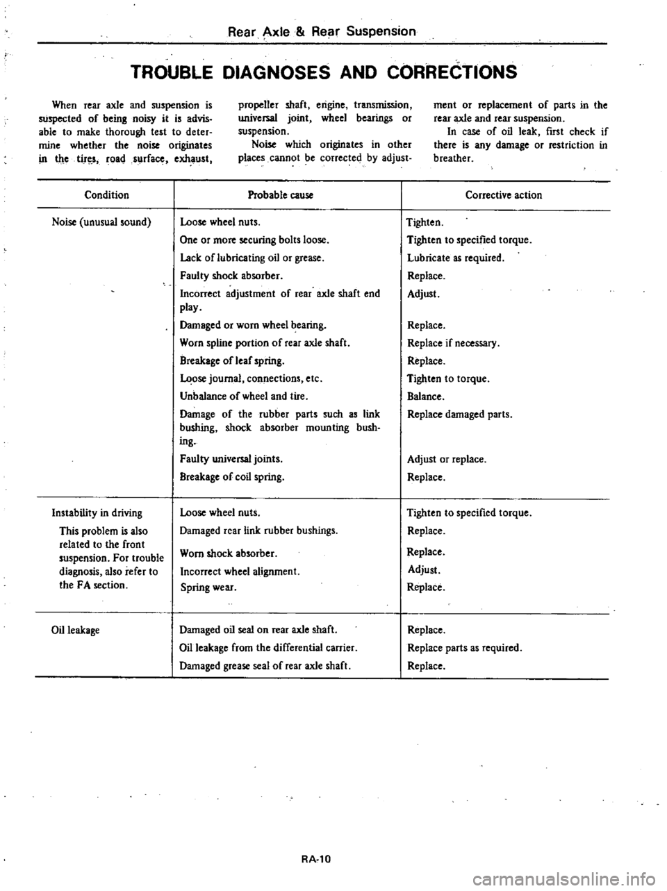
TROUBLE
DIAGNOSES
AND
CORRECTIONS
When
rear
axle
and
suspension
is
suspected
of
being
noisy
it
is
advis
able
to
make
thorough
test
to
deter
mine
whether
the
noise
originates
in
the
tir
s
roads
rfac
exhaust
propeller
shaft
engine
transmission
universal
joint
wheel
bearings
or
suspension
Noise
which
originates
in
other
places
cannot
be
corrected
by
adjust
Condition
Noise
unusual
sound
Instability
in
driving
This
problem
is
also
related
to
the
front
suspension
For
trouble
diagnosis
also
refer
to
the
FA
section
Oil
leakage
Probable
cause
Loose
wheel
nuts
One
or
more
securing
bolts
loose
Lack
oflubricating
oil
or
grease
Faulty
shock
absorber
Incorrect
adjustment
of
rear
axle
shaft
end
play
Damaged
or
worn
wheel
bearing
Worn
spline
portion
of
rear
axle
shaft
Breakage
of
leaf
spring
ose
journal
connections
etc
Unbalance
of
wheel
and
tire
Damage
of
the
rubber
parts
such
as
link
bU
hing
shock
absorber
moun
ting
bush
ing
Faulty
universal
joints
Breakage
of
coil
spring
Loose
wheel
nuts
Damaged
rear
link
rubber
bushings
Worn
shock
absorber
Incorrect
wheel
alignment
Spring
wear
Damaged
oil
seal
on
rear
axle
shaft
Oil
leakage
from
the
differential
carrier
Damaged
grease
seal
of
rear
axle
shaft
RA
l0
ment
or
replacement
of
parts
in
the
rear
axle
and
rear
suspension
In
case
of
oil
leak
first
check
if
there
is
any
damage
or
restriction
in
breather
Corrective
action
Tighten
Tighten
to
specified
torque
Lubricate
as
required
Replace
Adjust
Replace
Replace
if
necessary
Replace
Tighten
to
torque
Balance
Replace
damaged
parts
Adjust
or
replace
Replace
Tighten
to
specified
torque
Replace
Replace
Adjust
Replace
Replace
Replace
parts
as
required
Replace
Page 352 of 548
Rear
Axle
Rear
Suspension
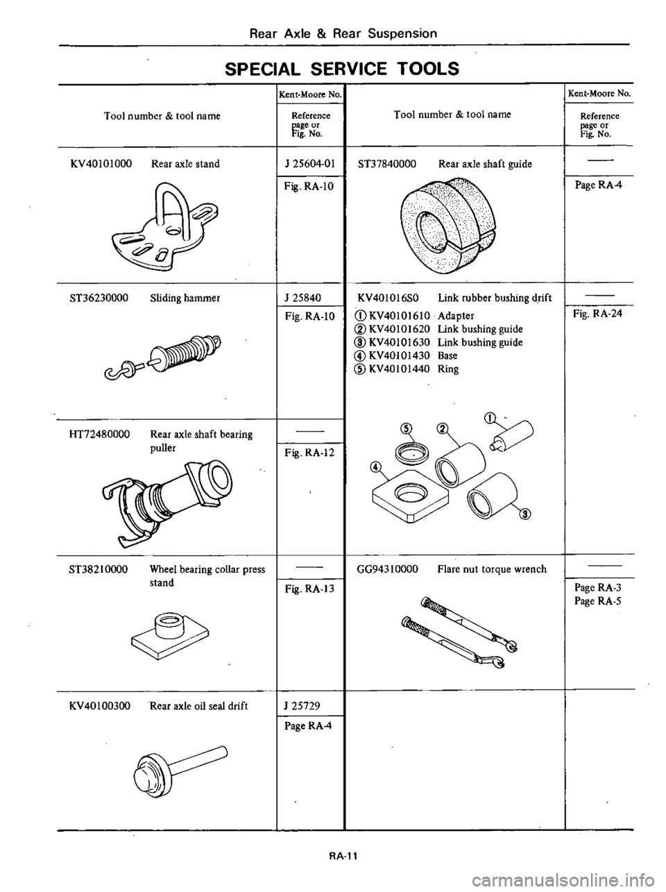
SPECIAL
SERVICE
TOOLS
Tool
number
tool
name
KV40101000
Rear
axle
stand
ST36230000
Sliding
hammer
esPY
HT72480000
Rear
axle
shaft
bearing
puller
ST38210000
Wheel
bearing
collar
press
stand
KV
401
00300
Rear
axle
oil
seal
drift
Kent
Moore
No
Reference
page
or
Fig
No
J
25604
01
Fig
RA
1O
J
25840
Fig
RA
1O
Fig
RA
12
Fig
RA
13
J
25729
Page
RA
4
Tool
number
tool
name
ST37840000
Rear
axle
shaft
guide
KV40l016S0
CD
KV40
10
I
610
V
KV40101620
ID
KV4010l630
@
KV40101430
CID
KV4010144
Link
rubber
bushing
drift
Adapter
Link
bushing
guide
Link
bushing
guide
Base
Ring
GG943
1
0000
Flare
nut
torque
wrench
RA
ll
Kent
Moore
No
Reference
page
or
Fig
No
Page
RA
4
Fig
RA
24
Page
RA
3
Page
RA
5
Page 353 of 548
DATSUN
2
0
Model
83
0
Series
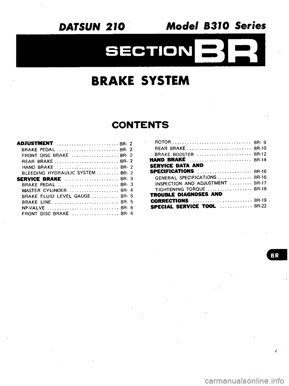
SECTIONBR
BRAKE
SYSTEM
CONTENTS
ADJUSTMENT
BRAKE
PEDAL
FRONT
DISC
BRAKE
REAR
BRAKE
HAND
BRAKE
BLEEDING
HYDRAULIC
SYSTEM
SERVICE
BRAKE
BRAKE
PEDAL
MASTER
CYLINDER
BRAKE
FLUID
LEVEL
GAUGE
BRAKE
LINE
NP
VALVE
FRONT
DISC
BRAKE
BR
2
BR
2
BR
2
BR
2
BR
2
BR
2
BR
3
BR
3
BR
4
BR
5
BR
5
BR
6
BR
6
ROTOR
REAR
BRAKE
BRAKE
BOOSTER
HAND
BRAKE
SERVICE
DATA
AND
SPECIFICATIONS
GENERAL
SPECIFICATIONS
INSPECTION
AND
ADJUSTMENT
TIGHTENING
TORQUE
TROUBLE
DIAGNOSES
AND
CORRECTIONS
SPECIAL
SERVICE
TOOL
BR
9
BR
l0
BR
12
BR
14
BR
16
BR
16
BR
17
BR
18
8R
19
8R
22
Page 354 of 548
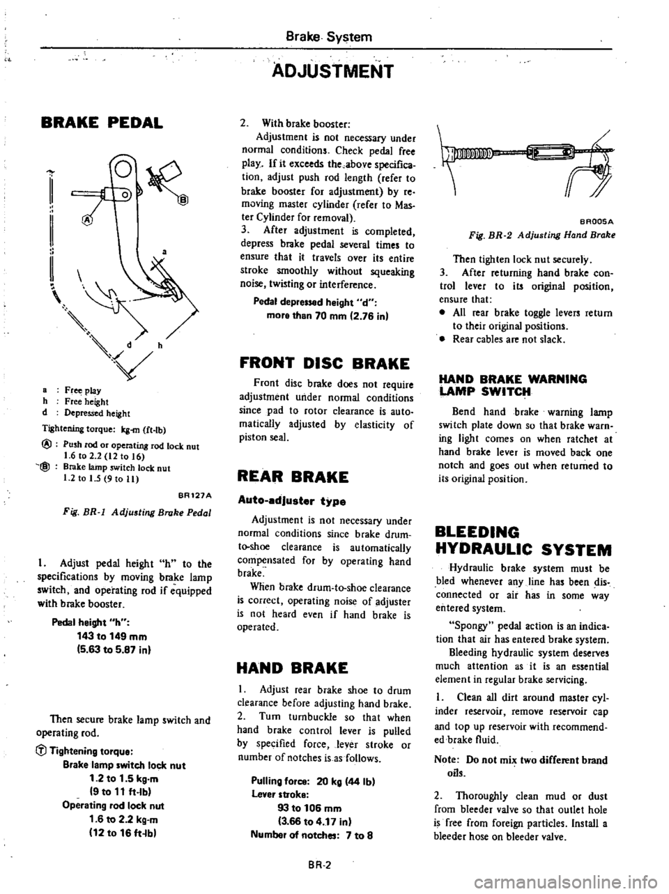
BRAKE
PEDAL
a
a
Fr
play
h
Free
height
d
Depressed
height
Tightening
torque
Icg
m
ft
tb
@
@
Push
rod
or
operating
rod
lock
nut
1
6
to
2
2
12
to
16
Brake
lainp
switch
lock
nut
1
2
to
I
5
9
to
11
BR121A
Fig
BR
1
Adjusting
Broke
Pedal
I
Adjust
pedal
height
h
to
the
specifications
by
moving
brake
lamp
switch
and
operating
rod
if
equipped
with
brake
booster
Pedal
height
h
143
to
149
mm
5
63
to
5
87
inl
Then
secure
brake
lamp
switch
and
operating
rod
C
l
Tightening
tOlque
Blake
lamp
witch
lock
nut
1
2
to
1
5
kg
m
9
to
11
ft
lb
Operating
lad
lock
nut
1
6
to
2
2
kg
m
12
to
16
ft
b
Brake
System
ADJUSTMENT
2
With
brake
booster
Adjustment
is
not
necessary
under
normal
conditions
Check
pedal
free
play
If
it
exceeds
the
above
specifica
tion
adjust
push
rod
length
refer
to
brake
booster
for
adjustment
by
re
moving
master
cylinder
rerer
to
Mas
ter
Cylinder
for
removal
3
After
adjustment
is
completed
depress
brake
pedal
several
times
to
ensure
that
it
travels
over
its
entire
stroke
smoothly
without
squeaking
noise
twisting
or
interference
Pedal
depr
d
Might
d
more
than
70
mm
2
76
in
FRONT
DISC
BRAKE
Front
disc
brake
does
not
require
adjustment
under
normal
conditions
since
pad
to
rotor
clearance
is
auto
malically
adjusted
by
elasticity
of
piston
seal
REAR
BRAKE
Auto
edJuster
type
Adjustment
is
not
necessary
under
normal
conditions
since
brake
drum
t
shoe
clearance
is
automatically
compensated
for
by
operating
hand
brake
Wlien
brake
drum
to
shoe
clearance
is
correct
operating
noise
of
adjuster
is
not
heard
even
if
hand
brake
is
operated
HAND
BRAKE
I
Adjust
rear
brake
shoe
to
drum
clearance
before
adjusting
hand
brake
2
Turn
turnbuckle
so
that
when
hand
brake
control
lever
is
pulled
by
specified
force
lever
stroke
or
number
of
notches
is
as
follows
Pulling
fOil
20
kg
44
Ib
lever
stroke
93
to
106
mm
3
66
to
4
17
in
Numbel
of
notches
7
to
8
BR
2
f
BAQ05A
Fig
BR
2
Adjusting
Hand
Brake
Then
tighten
lock
nut
securely
3
After
returning
hand
brake
con
trol
lever
to
its
original
position
ensure
that
e
All
rear
brake
toggle
levers
return
to
their
original
positions
Rear
cables
are
not
slack
HAND
BRAKE
WARNING
LAMP
SWITCH
Bend
hand
brake
warning
lamp
switch
plate
down
so
that
brake
warn
ing
light
comes
on
when
ratchet
at
hand
brake
lever
is
moved
back
one
notch
and
goes
out
when
returned
to
its
original
position
BLEEDING
HYDRAULIC
SYSTEM
Hydraulic
brake
system
must
be
bled
whenever
any
line
has
been
dis
connected
or
air
has
in
some
way
entered
system
Spongy
pedal
action
is
an
indica
tion
that
air
has
entered
brake
system
Bleeding
hydraulic
system
deserves
much
attention
as
it
is
an
essential
element
in
regular
brake
servicing
Clean
all
dirt
around
master
cyl
inder
reservoir
remove
reservoir
cap
and
top
up
reservoir
with
recommend
edbrake
fluid
Note
Do
not
mix
two
different
brand
oils
2
Thoroughly
clean
mud
or
dust
from
bleeder
valve
so
that
outlet
hole
is
free
from
foreign
particles
Install
a
bleeder
hose
on
bleeder
valve
Page 355 of 548
L
@
fl
JJ
l
f
m
ff
v
1
II
2
I
I
II
B
s1
r
Dip
other
end
of
hose
into
brake
fluid
bled
in
a
container
3
Pepress
brake
pedal
two
or
three
times
and
then
keep
pedal
fully
de
pressed
4
With
brake
pedal
fully
depressed
open
bleeder
valve
to
exhaust
air
Note
a
Carefully
monitor
brake
fluid
level
at
master
cylinder
during
bleeding
operation
BRAKE
PEDAL
REMOVAL
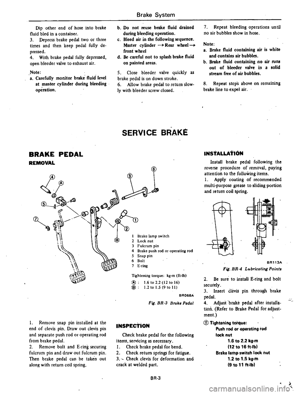
I
Remove
snap
pin
installed
at
the
end
of
clevis
pin
Draw
out
clevis
pin
and
separate
push
rod
or
operating
rod
from
brake
pedal
2
Remove
bolt
and
E
ring
securing
fulcrum
pin
and
draw
out
fulcrum
pin
Then
brake
pedal
can
be
taken
out
along
with
return
coil
spring
Brake
System
b
Do
not
reuse
brake
fluid
drained
during
bleeding
operation
c
Bleed
air
in
the
following
sequence
Master
cylinder
Rear
wheel
front
wheel
d
Be
careful
not
to
splash
brake
fluid
on
painted
areas
5
Close
bleeder
valve
quickly
as
brake
pedal
is
on
down
stroke
6
Allow
brake
pedal
to
return
slow
ly
with
bleeder
screw
closed
SERVI
CE
BRAKE
fJ
Brake
lamp
switch
Lock
nut
Fulcrum
pin
Brake
push
rod
or
operating
rod
Snap
pin
Bolt
E
ring
Tightening
torque
kg
m
ft
Ib
@
1
6
to
2
2
12
10
16
@
1
2
to
l
S
9
to
II
BROS8A
Fig
BR
3
Broke
Pedal
INSPEctioN
Check
brake
pedal
for
the
following
items
servicing
as
necessary
I
Check
brake
pedal
for
bend
2
Check
return
springs
for
fatigue
3
Check
clevis
for
deformation
and
crack
at
welded
part
BR
3
7
Repeat
bleeding
operations
until
no
air
bubbles
show
in
hose
Note
a
Brake
fluid
containing
air
is
white
and
contalns
air
bubbles
b
Brake
fluid
containing
no
air
rons
out
of
bleeder
valve
in
a
solid
stream
free
of
air
bubbles
8
Repeat
steps
above
on
remaining
brake
line
to
expel
air
INSTALLATION
Install
brake
pedal
following
the
reverse
procedure
of
removal
paying
attention
to
the
following
items
I
Apply
coating
of
recommended
multi
purpose
grease
to
sliding
portion
and
return
coil
spring
BA113A
Fit
BR
4
Lubricating
Point
2
Be
sure
to
install
E
ring
and
bolt
securely
3
Insert
CleviS
pin
through
brake
pedal
4
Adjust
brake
pedal
after
installa
tion
Refer
to
Blake
Pedal
for
adjust
ment
j
Tightening
torque
Push
rod
or
op8leting
rod
lock
nut
1
6
to
2
2
kltm
12
to
16
ft
Ibl
Brake
lamp
switch
lock
nut
1
2
to
1
5
kltin
9
to
11
ft
lb
Page 356 of 548
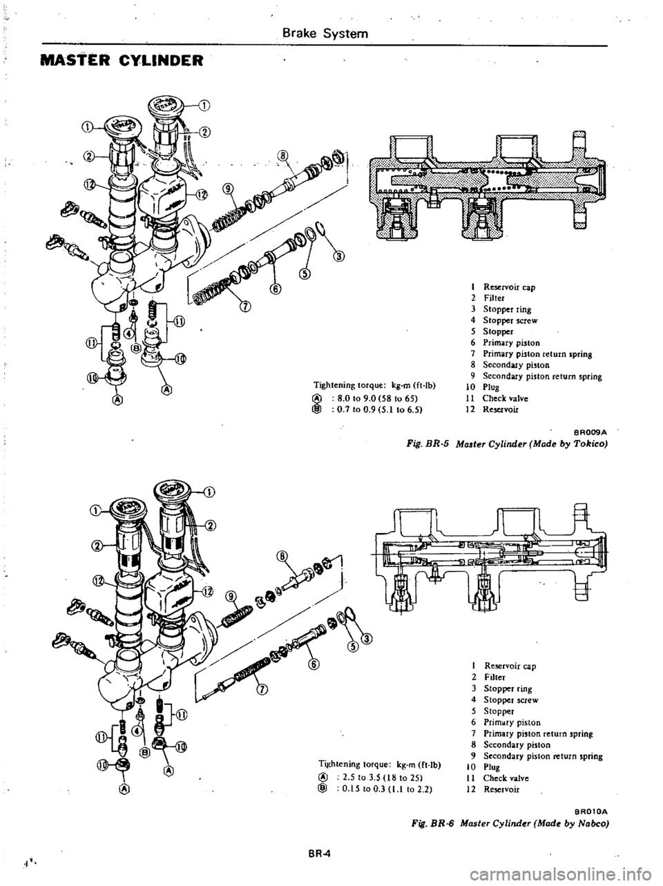
Tightening
torque
kg
m
ft
Ib
@
8
0
to
9
0
581065
@
0
7
to
0
9
5
1
to
6
5
I
Brake
System
MAstER
CYLINDER
I
Reservoir
cap
2
Filter
3
Stopper
ring
4
Stopper
Crew
5
Stopper
6
Primary
piston
7
Primary
piston
return
spring
8
Secondary
piston
9
Secondary
piston
return
spring
10
Plug
11
Check
valve
12
Reservoir
BR009A
Fig
BR
5
Ma
ler
Cylinder
Made
by
Tokico
1
Re
rvoir
cap
2
Filter
3
Stopper
ring
4
Stopper
screw
5
Stopper
6
Primary
piston
7
Primary
pinon
return
spring
8
Secondary
piston
9
Secondary
piston
return
spring
10
Plug
11
Check
valve
12
Reservoir
Tightening
torque
kg
m
ft
Ib
@
2
5
to
3
5
18
10
25
@
0
15
00
3
l
l
o
2
2
BR
4
I
BA010A
Fill
BR
6
Master
Cylinder
Made
by
Nabco
Page 357 of 548
REMOVAL
I
Disconnect
wiring
to
brake
fluid
level
gauge
2
Disconnect
front
and
rear
brake
tubes
from
master
cylinder
CAUTION
When
removing
brake
tubes
use
suitable
tube
wrench
Never
use
open
end
or
edjustllble
wrench
Note
When
disconnecting
brake
tubes
be
sure
to
use
a
container
to
receive
draining
brake
fluid
Use
of
raga
is
also
suggested
to
keep
adjacent
perts
and
area
clean
3
Remove
master
cylinder
securing
nut
Master
cylinder
can
then
be
taken
out
DISASSEMBLY
1
Remove
reservoir
caps
and
filtern
and
drain
out
brake
fluid
2
Pry
off
stopper
ring
using
a
screwdriver
3
Remove
stopper
screw
and
take
out
stopper
primary
piston
assembly
spring
and
secondary
piston
assembly
in
the
order
shown
Note
Discard
caps
if
they
are
reo
moved
from
piston
assemblies
and
use
new
ones
4
Unscrew
pluga
to
gain
access
to
check
valve
for
disassembling
Note
a
Never
detach
reservoir
tanks
If
they
are
removed
for
any
reason
discard
them
and
install
new
ones
b
Do
not
remove
or
disassemble
brake
fluid
level
gauge
INSPECTION
Thoroughly
clean
all
parts
in
a
suitable
solvent
and
check
them
for
wear
or
damage
Replace
any
part
that
is
faulty
Brake
System
CAUTION
Use
brake
fluid
to
clean
Never
use
mineral
oil
I
Check
cylinder
and
pistons
for
evidence
of
abnonnal
wear
or
damage
Replace
if
found
faulty
2
Check
piston
to
cylinder
clear
ance
If
it
exceeds
the
specified
value
replace
either
piston
or
cylinder
Piston
to
cylinder
clearance
less
than
0
15
mm
0
0059
in
3
Check
springs
for
weakness
fatigue
or
damage
Replace
if
neces
sary
4
When
master
cylinder
is
disas
sembled
be
sure
to
discard
caps
and
valves
Replace
any
other
parts
which
show
evidence
of
deformation
wear
or
other
damage
S
Replace
damaged
oil
reservoirs
and
caps
ASSEMBLY
Assemble
master
cylinder
following
the
reverse
procedure
of
disassembly
paying
particular
attention
to
the
fol
lowing
note
Note
a
Replace
gaskets
and
packing
with
new
ones
b
Apply
brake
fluid
or
rubber
grease
to
sliding
contact
surface
of
parts
to
facilitate
assembly
of
master
cylinder
c
The
brake
master
cylinder
is
avail
able
in
both
NABCO
make
and
TOKICO
make
There
is
no
inter
changeability
of
repair
kits
or
com
ponent
parts
between
NABCO
and
TOKlCO
makes
When
replacing
the
repair
kit
or
component
parts
ascertain
the
brand
of
the
brake
master
cylinder
body
Be
sure
to
use
parts
of
the
same
make
as
the
fonner
ones
INSTALLATION
Install
master
cylinder
following
the
reverse
procedure
of
removal
After
installation
bleed
brake
system
BR
5
CAUTION
When
installing
Flare
Nut
6694310000
brake
tubes
use
Torque
Wrench
CiJ
Tightening
torque
Brake
master
cylinder
securing
nut
0
8
to
t
1
kg
m
5
8
to
8
0
ft
lb
Brake
tube
flare
nut
1
5
to
1
8
kg
m
11
to
13
ft
b
BRAKE
FLUID
LEVEL
GAUGE
Inspection
I
Disengage
hand
brake
control
lever
2
Raise
cap
and
make
sure
that
hand
brake
warning
lamp
goes
on
when
float
comes
into
contact
with
stopper
BRAKE
LINE
REMOVAL
I
Remove
flare
nuts
on
both
ends
and
remove
retainers
and
clips
CAUTION
When
removing
brake
tubes
and
hoses
use
suitable
tube
wrench
Never
use
open
end
or
adjustable
wrench
2
To
remove
brake
hose
first
re
move
flare
nut
securing
brake
tube
to
brake
hose
and
withdraw
lock
spring
End
of
hose
can
then
be
removed
from
bracket
Next
remuve
brake
hose
Do
not
twist
brake
hose
INSPECTION
Check
brake
lines
tubes
and
hoses
for
evidence
of
cracks
deterioration
or
other
damage
Replace
any
faulty
parts
Page 358 of 548
If
leakage
oCcurs
at
end
around
joints
re
tighten
Of
if
necessary
re
place
faulty
parts
INSTALLATION
Pay
particular
attention
to
follow
ing
instructions
when
installing
brake
lines
I
Leave
a
sulfident
space
between
brake
lines
and
adjacent
parts
so
that
brake
lines
are
completely
free
from
vibration
during
driving
2
Be
careful
not
to
warp
or
twist
brake
lines
3
When
installing
brake
tube
keep
a
certain
distance
between
tube
and
adjacent
parts
as
follows
Tube
to
rotating
parts
30
mm
1
18
in
Tube
to
moving
parts
10
mm
10
39
in
Tube
to
other
palls
5
mm
10
20
in
4
Always
fasten
brake
tubes
with
mounting
clips
where
necessary
On
rear
axle
case
are
two
double
dips
which
should
be
used
to
secure
brake
tubes
in
manner
described
be
low
Bend
short
clip
straight
up
With
brake
tube
on
long
clip
bend
clip
up
and
around
tube
Finally
wrap
short
clip
around
tube
to
secure
the
in
slallation
f
J
i
2
BA141
Fig
BR
7
Fastening
Brake
Tube
Securely
with
Double
Clip
5
Do
not
tighten
brake
line
mount
ing
flare
nut
excessively
CAUTION
When
installing
Fla
e
Nut
6694310000
brake
tubes
use
Torque
Wrench
Brake
System
t
D
Tightening
torque
Brake
tube
flare
nut
1
5
to
1
8
kg
m
11
to
13
ft
lb
Brake
hose
connector
1
7
to
2
0
kg
m
112
to
14
ft
lb
J
way
connector
bolt
0
8
to
1
1
kltm
5
8
to
8
0
ft
Ib
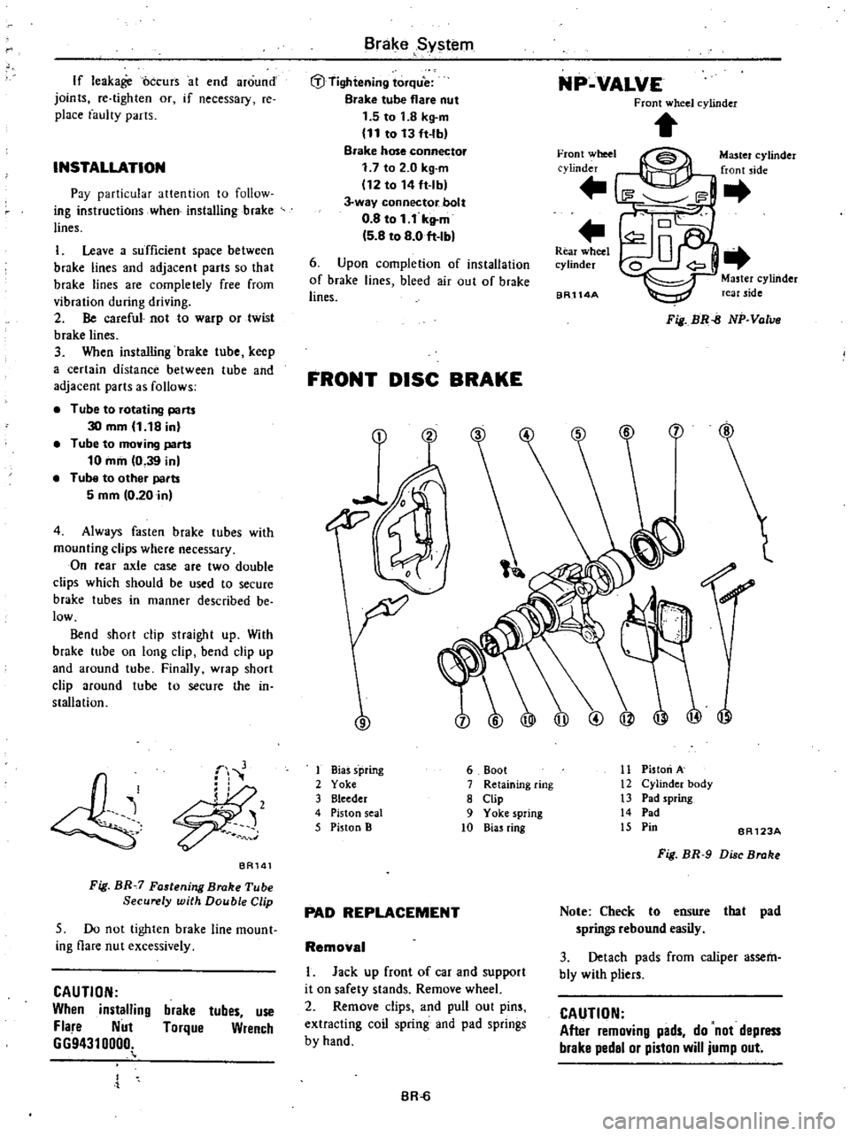
NP
VALVE
Front
wheel
cylinder
Front
wheel
cylinder
Master
cylinder
front
jde
6
Upon
completion
of
installation
of
brake
lines
bleed
air
out
of
brake
lines
Rear
wheel
cylinder
BR114A
Master
cylinder
rear
side
Fig
BR
B
NP
Valve
FRONT
DISC
BRAKE
9
ilJ
I
Bias
s
pring
2
Yoke
3
Bleeder
4
Piston
seal
5
Piston
B
11
Piston
A
12
Cylinder
body
13
Pad
spring
14
Pad
15
Pin
6
Boot
7
Retaining
ring
8
Clip
9
Yoke
spring
10
Bias
ring
BR123A
Fig
BR
9
Di
c
Broke
PAD
REPLACEMENT
Note
Check
to
ensure
that
pad
springs
rebound
easily
3
Detach
pads
from
caliper
assem
bly
with
pliers
Removal
I
Jack
up
front
of
car
and
support
it
on
safety
stands
Remove
wheel
2
Remove
clips
and
pull
out
pins
extracting
coil
spring
and
pad
springs
by
hand
CAUTION
After
removing
pads
do
not
depress
brake
pedal
or
piston
will
jump
out
BR
Page 359 of 548
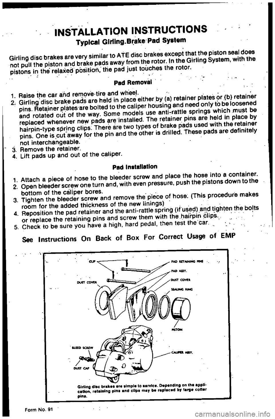
INSTALLATION
INSTRUCTIONS
Typical
Glrllng
B
ake
Pad
SYIlem
Girling
disc
brakes
are
very
similar
to
ATE
disc
brakes
except
that
the
piston
seal
does
not
pul
the
piston
and
brake
pads
away
from
the
rotor
In
the
Girling
System
with
the
pistons
i
the
relaxeilposition
the
pad
just
touches
the
rotor
Ped
Removal
1
Raise
the
car
alid
removiHire
and
wheel
2
Girling
disc
brake
pads
ere
held
in
piece
either
by
a
retainer
plates
or
b
retainer
pins
Retainer
plates
are
boiled
to
the
caliper
housing
and
need
only
to
be
loosened
and
roteted
out
of
the
way
Some
models
use
anti
raWe
springs
which
must
be
replaced
whenever
new
pads
ere
installed
The
retainer
pins
are
held
in
place
by
hairpin
type
spring
clips
There
are
two
types
of
breke
pads
used
with
the
retainer
pins
One
is
cut
away
for
the
pin
end
the
other
is
drilled
These
padS
ere
definitely
not
interchengeable
3
Remove
the
reteiner
4
Lift
padS
up
and
out
of
the
celiper
Pad
Installation
1
Attach
a
piece
of
hose
to
the
bleeder
screw
and
place
the
hose
into
a
container
2
Open
bleeder
screw
one
turn
and
with
even
pressure
push
the
pistons
down
to
the
bottom
of
the
caliper
bores
3
Tighten
the
bleeder
screw
and
remove
the
piece
o
hose
This
procedure
makes
room
for
the
added
thickness
of
the
new
linings
4
Reposition
the
pad
retainer
and
the
anti
rattle
spring
i
used
and
tighten
the
bolts
or
replace
the
retaining
pins
and
screw
them
with
the
hairpin
Iips
5
Check
to
be
sure
you
have
a
high
hard
pedal
then
test
the
car
See
Instructions
On
Back
of
Ball
For
Correct
Usage
of
EMP
Gh11ng
dlac
brall
Ilmple
to
art
lc
Depending
III
ppU
aUon
atalnln
pilla
nd
clip
may
blt
placed
by
larga
QU
pin
Form
No
91
Page 360 of 548
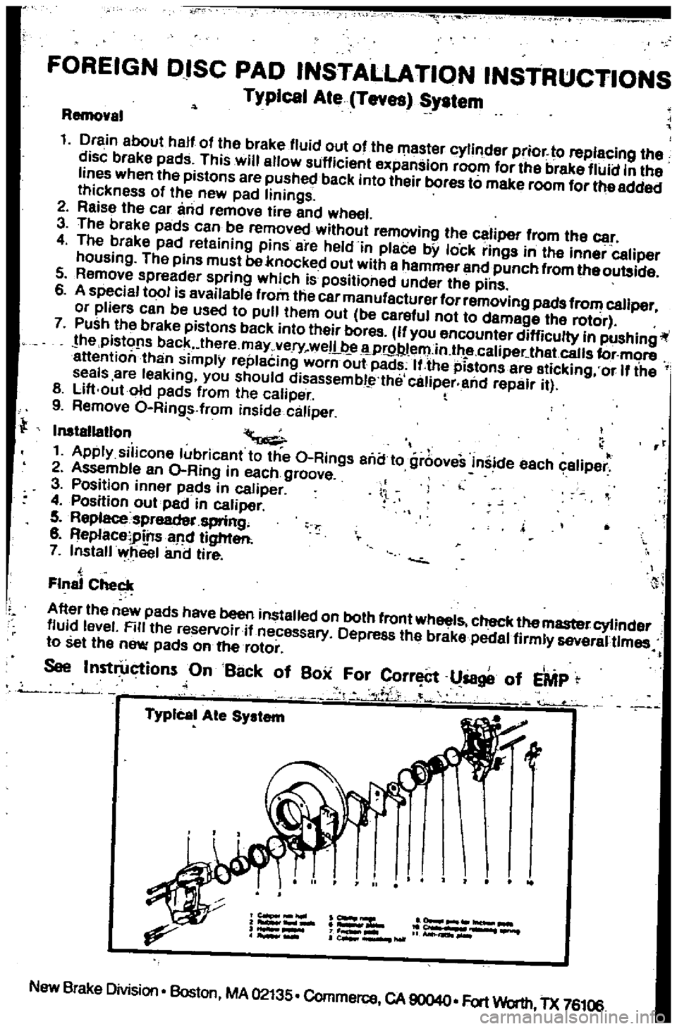
FOREIGN
DISC
PAD
INSTALLATION
INSTRUCTIONS
Typical
Ate
Teves
System
Removel
1
Drain
about
half
of
the
brake
fluid
out
of
the
master
cylinder
prior
to
replacing
the
disc
brake
pads
This
will
allow
sufficient
expansion
room
for
the
brake
fluid
in
the
lines
when
the
pistons
are
pushed
back
into
their
bores
to
make
room
for
the
added
Ihickness
of
the
new
pad
linings
2
Reise
the
car
and
lemove
tire
and
wheel
3
The
breke
pads
can
be
removed
without
lemovinll
the
caliper
from
the
car
4
The
brake
pad
reteining
pins
are
held
in
plaCe
bY
lock
rinlls
in
Ihe
inner
caliper
housing
The
pins
must
be
knocked
out
with
e
hammel
end
punch
from
theoulllide
5
Remove
spreader
spring
which
is
positioned
under
the
pins
6
A
special
tool
is
available
flom
the
car
manufacturer
forremoving
pads
from
caliper
or
pliers
can
be
used
to
pull
them
oul
be
careful
not
to
damage
the
rotor
7
Push
Ihe
brake
pistons
back
into
their
boros
If
you
encounter
difficulty
in
pushingil
he
pistofls
back
lhere
may
very
weIL
Wr9Jl
l
ern
in
lh
e
caliper
that
calls
for
more
attention
than
simplY
replecing
worn
out
pads
IUhe
pistons
are
eticking
or
If
the
seals
are
leaking
you
should
disassembl
the
caliper
and
repair
il
8
Lift
out
old
pads
from
Ihe
caliper
9
Remove
O
Ring
from
inside
caliper
Inslallatlon
II
1
Apply
silicone
lubricanl
to
Ihe
O
Rings
ana
to
grooveS
inside
each
caliper
2
Assemble
an
O
Ring
in
each
groove
3
Position
innor
pads
in
caliper
4
Position
oulpad
in
caliper
5
Replacespreadet
spring
8
ReplaceiPtnsaM
lighter
7
Install
wheel
and
lire
l
Final
Checl
A
Iter
Ihe
new
padS
have
been
installed
on
bolh
front
wheel
check
the
master
cylinder
fluid
level
Rlllhe
reservoiril
necessary
Depress
Ihe
brake
pedal
firmly
severaUlmes
to
sellhe
new
pads
on
he
rotor
i
See
Inst
ctionsOnBat
k
of
Box
For
rr
l8ge
of
EMP
l
iL
1
f
J
TypIcal
Ale
System
New
Brake
Division
Boston
MA
02135
Commerce
CA
90040
Fort
Worth
TX
76106