DATSUN B110 1973 Service Repair Manual
Manufacturer: DATSUN, Model Year: 1973, Model line: B110, Model: DATSUN B110 1973Pages: 513, PDF Size: 28.74 MB
Page 111 of 513
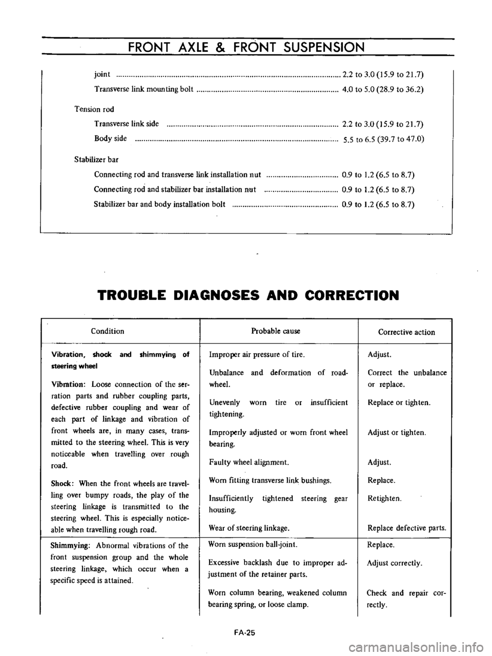
FRONT
AXLE
FRONT
SUSPENSION
joint
Transverse
link
mounting
bolt
Tension
rod
Transverse
link
side
Body
side
Stabilizer
bar
Connecting
rod
and
transverse
link
installation
nut
Connecting
rod
and
stabilizer
bar
installation
nut
Stabilizer
bar
and
body
installation
bolt
2
2
to
3
0
15
9
to
21
7
4
0
to
5
0
28
9
to
36
2
2
2
to
3
0
15
9
to
217
5
5
to
6
5
39
7
to
47
0
0
9
to
1
2
6
5
to
8
7
0
9
to
1
2
6
5
to
8
7
0
9
to
1
2
6
5
to
8
7
TROUBLE
DIAGNOSES
AND
CORRECTION
Condition
Vibration
shock
and
shimmying
of
steering
wheel
Vibmtion
Loose
connection
of
the
ser
ration
parts
and
rubber
coupling
parts
defective
rubber
coupling
and
wear
of
each
part
of
linkage
and
vibration
of
front
wheels
are
in
many
cases
trans
mitted
to
the
steering
wheeL
This
is
very
noticeable
when
travelling
over
rough
road
Shock
When
the
front
wheels
are
travel
ling
over
bumpy
roads
the
play
of
the
steering
linkage
is
transmitted
to
the
steering
wheeL
This
is
especially
notice
able
when
travelling
rough
road
Shimmying
Abnormal
vibrations
of
the
front
suspension
group
and
the
whole
steering
linkage
which
occur
when
a
specific
speed
is
attained
Probable
cause
Improper
air
pressure
of
tire
Unbalance
and
deformation
of
road
wheeL
Unevenly
worn
tire
or
insufficient
tightening
Improperly
adjusted
or
worn
front
wheel
bearing
Faulty
wheel
alignment
Worn
fitting
transverse
link
bushings
Insufficiently
tightened
steering
gear
housing
Wear
of
steering
linkage
Worn
suspension
ball
joint
Excessive
backlash
due
to
improper
ad
justment
of
the
retainer
parts
Worn
column
bearing
weakened
column
bearing
spring
or
loose
clamp
FA
25
Corrective
action
Adjust
Correct
the
unbalance
or
replace
Replace
or
tighten
Adjust
or
tighten
Adjust
Replace
Retighten
Replace
defective
parts
Replace
Adjust
correctly
Check
and
repair
cor
rectly
Page 112 of 513
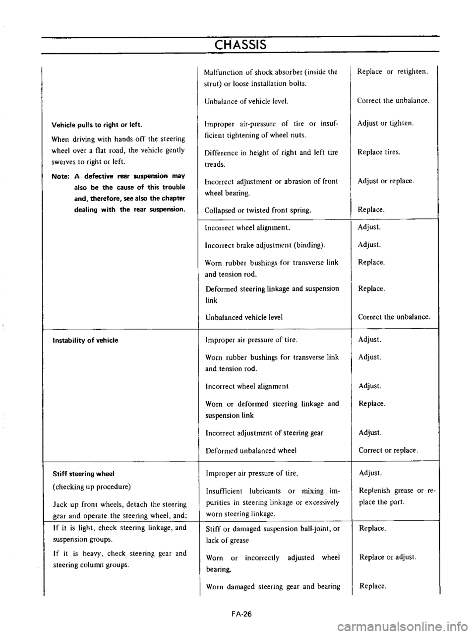
Vehicle
pulls
to
right
or
left
When
driving
with
hands
off
the
steering
wheel
over
a
flat
road
the
vehicle
gently
swerves
to
right
or
left
Note
A
defective
rear
suspension
may
also
be
the
cause
of
this
trouble
and
therefore
see
also
the
chapter
dealing
with
the
rear
suspension
Instability
of
vehicle
Stiff
steering
wheel
checking
up
procedure
Jack
up
front
wheels
detach
the
steering
gear
and
operate
the
steering
wheel
and
If
it
is
light
check
steering
linkage
and
suspension
groups
If
it
is
heavy
check
steering
gear
and
steering
colunm
groups
CHASSIS
Malfunction
of
shock
absorber
inside
the
strut
or
loose
installation
bolts
Unbalance
of
vehicle
level
Improper
air
pressure
of
tire
or
insuf
ficient
tightening
of
wheel
nuts
Difference
in
height
of
right
and
left
tire
treads
Incorrect
adjustment
or
abrasion
of
front
wheel
bearing
Collapsed
or
twisted
front
spring
Incorrect
wheel
alignment
Incorrect
brake
adjustment
binding
Worn
rubber
bushings
for
transverse
link
and
tension
rod
Deformed
steering
linkage
and
suspension
link
Unbalanced
vehicle
level
Improper
air
pressure
of
tire
Worn
rubber
bushings
for
transverse
link
and
tension
rod
Incorrect
wheel
alignment
Worn
or
deformed
steering
linkage
and
suspension
link
Incorrect
adjustment
of
steering
gear
Deformed
unbalanced
wheel
Improper
air
pressure
of
tire
Insufficient
lubricants
or
mixing
im
purities
in
steering
linkage
or
excessively
worn
steering
linkage
Stiff
or
damaged
suspension
ball
joint
or
lack
of
grease
Worn
or
incorrectly
adjusted
wheel
bearing
Worn
damaged
steering
gear
and
bearing
FA
26
Replace
or
retighten
Correct
the
unbalance
Adjust
or
tighten
Replace
tires
Adjust
or
replace
Replace
Adjust
Adjust
Replace
Replace
Correct
the
unbalance
Adjust
Adjust
Adjust
Replace
Adjust
Correct
or
replace
Adjust
Repl
nish
grease
or
re
place
the
part
Replace
Replace
or
adjust
Replace
Page 113 of 513
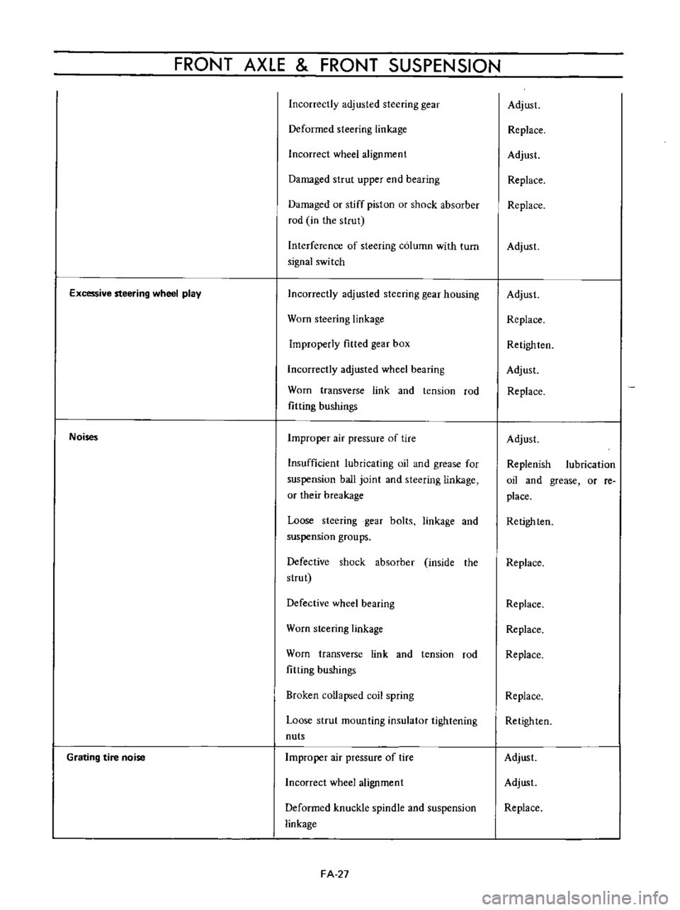
FRONT
AXLE
FRONT
SUSPENSION
Incorrectly
adjusted
steering
gear
Deformed
steering
linkage
Incorrect
wheel
alignment
Damaged
strut
upper
end
bearing
Damaged
or
stiff
piston
or
shock
absorber
rod
in
the
strut
Interference
of
steering
column
with
turn
signal
switch
Excessive
steering
wheel
play
Noises
Grating
tire
noise
Incorrectly
adjusted
steering
gear
housing
Worn
steering
linkage
Improperly
fitted
gear
box
Incorrectly
adjusted
wheel
bearing
Worn
transverse
link
and
tension
rod
fitting
bushings
Improper
air
pressure
of
tire
Insufficient
lubricating
oil
and
grease
for
suspension
ball
joint
and
steering
linkage
or
their
breakage
Loose
steering
gear
bolts
linkage
and
suspension
groups
Defective
shock
absorber
inside
the
strut
Defective
wheel
bearing
Worn
steering
linkage
Worn
transverse
link
and
tension
rod
fitting
bushings
Broken
collapsed
coil
spring
Loose
strut
mounting
insulator
tightening
nuts
Improper
air
pressure
of
tire
Incorrect
wheel
alignment
Deformed
knuckle
spindle
and
suspension
linkage
FA
27
Adjust
Replace
Adjust
Replace
Replace
Adjust
Adjust
Replace
Retighlen
Adjust
Replace
Adjust
Replenish
lubrication
oil
and
grease
or
re
place
Retighten
Replace
Replace
Replace
Replace
Replace
Retighten
Adjust
Adjust
Replace
Page 114 of 513
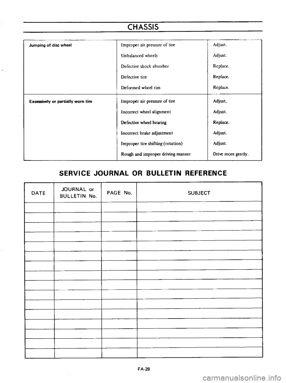
CHASSIS
Jumping
of
disc
wheel
Improper
air
pressure
of
tire
Adjust
Unbalanced
wheels
Adjust
Defective
shock
absorber
Replace
Defective
tire
Replace
Deformed
wheel
rim
Replace
Excessively
or
partially
worn
tire
Improper
air
pressure
of
tire
Adjust
Incorrect
wheel
alignment
Adjust
Defective
wheel
bearing
Replace
Incorrect
brake
adjustment
Adjust
Improper
tire
shifting
rotation
Adjust
Rough
and
improper
driving
manner
Drive
more
gently
SERVICE
JOURNAL
OR
BULLETIN
REFERENCE
DATE
JOURNAL
or
BULLETIN
No
PAGE
No
SUBJECT
FA
28
Page 115 of 513
DATSUN
1200
MODEL
B
1
10
SERIES
I
NISSAN
I
NISSAN
MOTOR
CO
LTD
TOKYO
JAPAN
SECTION
RA
REAR
AXLE
REAR
SUSPENSION
REAR
AXLE
REAR
SUSPENSION
SERVICE
DATA
AND
SPECIFICATIONS
RA
1
RA
4
RA
7
Page 116 of 513
REAR
AXLE
REAR
SUSPENSION
REAR
AXLE
CONTENTS
DESCRIPTION
REAR
AXLE
SHAFTS
Removal
RA
1
RA
l
RA
l
8
Inspection
Assembly
RA
3
RA
3
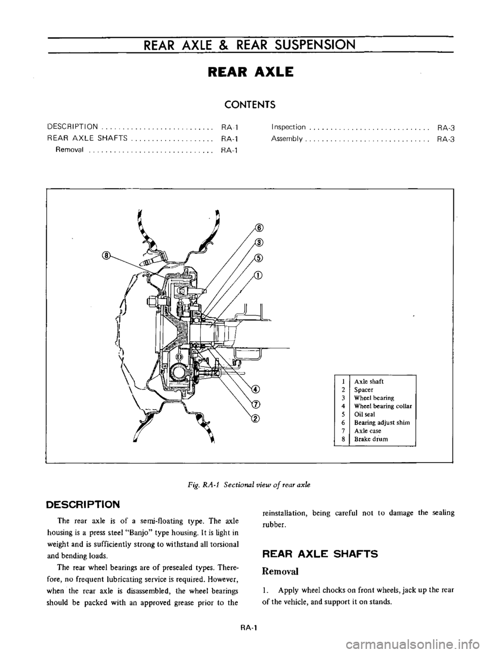
1
Axle
shaft
2
Spacer
3
Wheel
bearing
4
Wheel
bearing
collar
5
Oil
seal
6
Bearing
adjust
shim
7
Axle
case
8
Brake
drum
DESCRIPTION
Fig
RA
l
Sectional
view
of
rear
axle
The
rear
axle
is
of
a
semi
floating
type
The
axle
housing
is
a
press
steel
Banjo
type
housing
It
is
light
in
weight
and
is
sufficiently
strong
to
withstand
all
torsional
and
bending
loads
The
rear
wheel
bearings
are
of
presea1ed
types
There
fore
no
frequent
lubricating
service
is
required
However
when
the
rear
axle
is
disassembled
the
wheel
bearings
should
be
packed
with
an
approved
grease
prior
io
the
reinstallation
being
careful
not
to
damage
the
sealing
rubber
REAR
AXLE
SHAFTS
Removal
Apply
wheel
chocks
on
front
wheels
jack
up
the
rear
of
the
vehicle
and
support
it
on
stands
RA
l
Page 117 of 513
CHASSIS
2
Remove
the
wheel
cover
and
nuts
Remove
the
road
wheel
and
b
rake
drum
If
brake
linings
should
hold
the
drum
slacken
off
the
brake
shoe
adjuster
a
few
notches
3
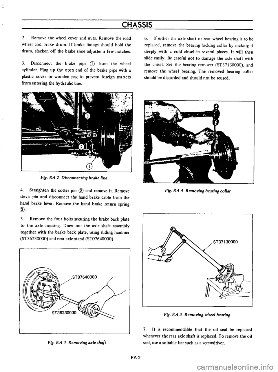
Disconnect
the
brake
pipe
CD
from
the
wheel
cylinder
Plug
up
the
open
end
of
the
brake
pipe
with
a
plastic
cover
or
wooden
peg
to
prevent
foreign
matters
from
entering
the
hydraulic
line
Fig
RA
2
Disconnecting
brake
Une
4
Straighten
the
cotler
pin
@
and
remove
it
Remove
clevis
pin
and
disconnect
the
hand
brake
cable
from
the
hand
brake
lever
Remove
the
hand
brake
return
spring
CID
5
Remove
the
four
bolts
securing
the
brake
back
plate
to
the
axle
housing
Draw
out
the
axle
shaft
assembly
together
with
the
brake
back
plate
using
sliding
hammer
ST36230000
and
rear
axle
stand
ST07640000
ST07640000
I
Fig
RA
3
Removing
axle
shaft
6
If
either
the
axle
shaft
or
rear
wheel
bearing
is
to
be
replaced
remove
the
bearing
locking
collar
by
nicking
it
deeply
with
a
cold
chisel
in
several
places
It
will
then
slide
easily
Be
careful
not
to
damage
the
axle
shaft
with
the
chiscl
Set
the
bearing
remover
ST37130000
and
remove
the
wheel
bearing
The
removed
bearing
collar
should
be
discarded
and
should
not
be
reused
Fig
RA
4
Removing
bearing
collar
Fig
RA
5
Removing
wheel
bearing
7
It
is
recommendable
that
the
oil
seal
be
replaced
whenever
the
rear
axle
shaft
is
replaced
To
remove
the
oil
seal
use
a
suitable
bar
such
as
a
screwdriver
RA
2
Page 118 of 513
REAR
AXLE
REAR
SUSPENSION
y
Jo
r
J
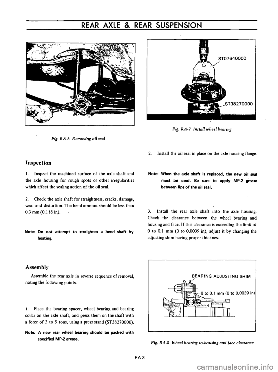
Fig
RA
6
Removing
oil
seal
Inspection
I
Inspect
the
machined
surface
of
the
axle
shaft
and
the
axle
housing
for
rough
spots
or
other
irregularities
which
affect
the
sealing
action
of
the
oil
seal
2
Check
the
axle
shaft
for
straightness
cracks
damage
wear
and
distortion
The
bend
amount
should
be
less
than
0
3
mm
0
118
in
Note
Do
not
attempt
to
straighten
a
bend
shaft
by
heating
Assembly
Assemble
the
rear
axle
in
reverse
sequence
of
removal
noting
the
following
points
I
Place
the
bearing
spacer
wheel
bearing
and
bearing
collar
on
the
axle
shaft
and
press
them
on
the
shaft
with
a
force
of
3
to
5
tons
using
a
press
stand
ST38270000
Note
A
new
rear
wheel
bearing
should
be
packed
with
specified
MP
2
grease
Fig
RA
7
Install
wheel
bearing
2
Install
the
oil
seai
in
place
on
the
axle
housing
flange
Note
When
the
axle
shaft
is
replaced
the
new
oil
seal
must
be
used
Be
sure
to
apply
MP
2
grease
between
lips
of
the
oil
seal
3
Install
the
rear
axle
shaft
into
the
axle
housing
Check
the
clearance
between
the
wheel
bearing
and
housing
and
face
If
this
clearance
is
exceeding
the
limit
of
o
to
0
1
mm
0
to
0
0039
in
adjust
it
by
changing
the
adjusting
shim
having
proper
thickness
BEARING
ADJUSTING
SHIM
1
Fig
RA
8
Wheel
bearing
to
housing
end
face
clearance
RA
3
Page 119 of 513
CHASSIS
4
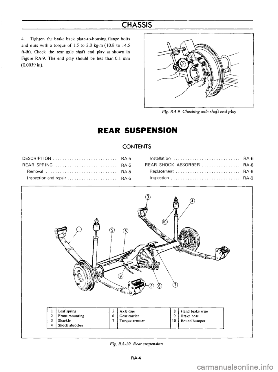
Tighten
he
brake
back
plate
to
housing
nunge
bults
and
nuts
with
a
torque
of
1
5
to
2
0
kg
m
10
8
to
145
ft
Ibl
Check
the
rear
axle
shaft
end
playas
shown
in
Figure
RA
9
The
end
plav
should
be
less
than
U
I
nun
0
0039
in
Fig
RA
9
Checking
axle
shaft
end
play
REAR
SUSPENSION
CONTENTS
DESCRIPTION
REAR
SPRING
Removal
I
nspection
and
repair
RA
5
RA
5
RA
5
RA
5
I
n5tallatlon
REAR
SHOCK
ABSORBER
Replacement
Inspection
RA
6
RA
6
RA
6
RA
6
0
tr
1
1
@
5
@
7
I
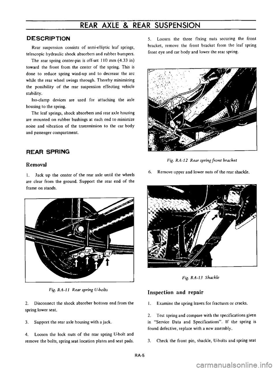
Leaf
spring
5
Axle
case
8
Hand
brake
wire
2
Front
mounting
6
Gear
carrier
9
Brake
hose
3
Shackle
7
Torque
arrester
10
Bound
bumper
4
Shock
absorber
Fig
RA
10
Rear
suspension
RA
4
Page 120 of 513
REAR
AXLE
REAR
SUSPENSION
DESCRIPTION
Rear
suspension
consists
of
semi
elliptic
leaf
springs
telescopic
hydraulic
shock
absorbers
and
rubber
bumpers
The
rear
spring
center
pin
is
off
set
110
mm
4
33
in
toward
the
front
from
the
center
of
the
spring
This
is
done
to
reduce
spring
wind
up
and
to
decrease
the
arc
while
the
rear
wheel
swings
through
Thereby
minimizing
the
possibility
of
the
rear
suspension
effecting
vehicle
stability
Iso
clamp
devices
are
used
for
attaching
the
axle
housing
to
the
spring
The
leaf
springs
shock
absorbers
and
rear
axle
housing
are
mounted
on
rubber
bushings
at
each
end
to
minimize
noise
and
vibration
of
the
transmission
to
the
car
body
and
passenger
compartment
REAR
SPRING
Removal
1
Jack
up
the
center
of
the
rear
axle
until
the
wheels
are
clear
from
the
ground
Support
the
rear
end
of
the
frame
on
stands
Fig
RA
l1
Rear
spring
U
bo
ts
2
Disconnect
the
shock
absorber
bottom
end
from
the
spring
lower
seat
3
Support
the
rear
axle
housing
with
a
jack
4
Loosen
the
lock
nuts
of
the
rear
spring
U
bolt
and
remove
the
bolts
spring
seat
location
plates
and
seat
pads
5
Loosen
the
three
fixing
nuts
securing
the
front
bracket
remove
the
front
bracket
from
the
leaf
spring
front
eye
and
car
body
and
lower
the
rear
spring
Fig
RA
12
Rear
spring
front
bracket
6
Remove
upper
and
lower
nuts
of
the
rear
shackle
Fig
RA
13
Shackle
Inspection
and
repair
1
Examine
the
spring
leaves
for
fractures
or
cracks
2
Test
spring
and
compare
with
the
specifications
given
in
Service
Data
and
Specifications
If
the
spring
is
found
defective
replace
with
a
new
assembly
3
Check
the
front
pin
shackle
U
bolts
and
spring
seat
RA
5