check DATSUN PICK-UP 1977 Service Manual
[x] Cancel search | Manufacturer: DATSUN, Model Year: 1977, Model line: PICK-UP, Model: DATSUN PICK-UP 1977Pages: 537, PDF Size: 35.48 MB
Page 389 of 537
f
BR317
Fig
BR
23
Gre
ing
point
4
Tightening
torque
Wheel
cylinder
J
S
to
1
8
kg
m
II
to
13ft
Ib
Connector
bolt
1
9
to
2
5
kg
m
14
to
18
ft
Ib
Brake
tube
1
5
to
1
8
kg
m
II
to
13
ft
Ib
Air
bleeder
0
7
to
0
9
kg
m
S
to
7
ft
Ib
Brake
disc
5
4
to
6
4
kg
m
39
to
46
ft
Ib
S
Adjust
brake
shoe
clearance
and
bleed
brake
system
Upon
completion
of
the
above
adjustments
make
sure
that
brake
operates
correctly
and
no
brake
fluid
leaks
MASTER
VAC
DESCRIPTION
A
vacuum
suspended
Master
Vac
is
installed
behind
the
master
cylinder
As
the
brake
pedal
is
depressed
fluid
is
forced
under
high
pressure
through
the
brake
pipes
to
the
wheel
cylinders
to
retard
or
stop
the
vehicle
The
Master
Vac
contains
a
spring
loaded
diaphragm
of
IS2
4
mm
6
in
in
diameter
It
operates
on
negative
pressure
produced
n
the
engine
intake
manifold
The
tandem
master
cylinder
is
capable
of
producing
high
pressure
even
if
the
Master
Vac
is
faulty
Brake
System
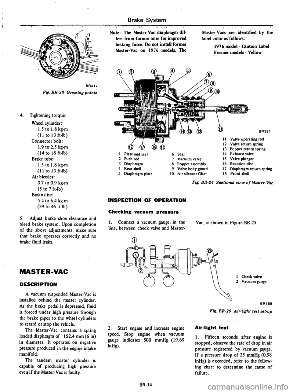
Note
The
Master
Vac
diaphragm
dif
fers
from
fonner
ones
for
improved
braking
force
Do
not
install
fonner
Master
Vac
on
1976
models
The
1
Plate
and
seal
2
Push
rod
3
Diaphragm
4
Rear
shell
5
Diaphragm
plate
Master
Vacs
are
identified
by
the
label
color
as
follows
1976
model
Caution
Label
Former
models
YeJlow
BR321
11
Valve
operating
rod
12
Valve
return
spring
13
Poppet
return
spring
14
Exhaust
valve
15
Valve
plunger
16
Reaction
disc
17
Diaphragm
return
spring
18
Front
shell
6
Seal
7
Vacuum
valve
8
Poppet
assembly
9
Valve
body
guard
10
Air
silencer
filter
INSPECTION
OF
OPERATION
Checking
yscuum
pressure
I
Connect
a
vacuum
gauge
in
the
line
between
check
valve
and
Master
2
Start
engine
and
increase
engine
speed
Stop
engine
when
vacuum
gauge
indicates
SOO
mmHg
19
69
inHg
BR
14
Fig
BR
24
Sectionall1iew
of
Master
Vac
Vac
as
shown
in
Figure
BR
25
1
Check
valve
2
Vacuum
gauge
BA169
Fig
BR
25
Air
tight
t
t
t
up
Air
tight
test
I
Fifteen
seconds
after
engine
is
stopped
observe
the
rate
of
drop
in
air
pressure
registered
by
vacuum
gauge
If
a
pressure
drop
of
25
mmHg
0
98
inHg
is
exceeded
refer
to
the
follow
ing
chart
to
determine
the
cause
of
failure
Page 390 of 537
Probable
cause
I
Air
leakago
at
check
valve
2
Air
leakage
a
t
push
rod
seal
3
Air
leakage
between
valve
body
and
seal
4
Air
leakage
at
valve
plunger
seat
5
Damaged
piping
or
joints
2
Fifteen
seconds
after
engine
is
stopped
and
brake
fully
applied
ob
serve
the
rate
of
drop
in
air
pressure
registered
by
vacuum
gauge
Probable
cause
1
Air
leakage
at
check
valve
2
Damaged
diaphragm
3
Reaction
disc
dropped
off
4
Air
leakage
at
and
valve
body
poppet
assembly
seat
Note
When
replacement
of
any
part
is
required
be
sure
to
renew
Master
Vac
as
an
assembly
Inspecting
check
valve
Remove
clip
and
disconnect
hoses
at
connections
The
check
valve
can
now
be
removed
yr
BA3
Fig
BR
26
Location
of
check
valve
2
Using
a
Master
Vac
tester
apply
a
vacuum
pressure
of
200
mmHg
7
87
inHg
to
the
port
of
check
valve
on
the
Master
Vac
side
If
a
pressure
drop
of
10
mmHg
0
39
inHg
is
exceeded
in
1
I
I
17
I
f
I
I
I
Z
I
I
y1
I
I
I
7
I
I
I
I
I
I
I
I
I
I
y1
II
I
I
I
I
I
I
I
L
I
L
5
to
15
20
25
30
35
40
45
50
55
60
22
44
66
88
110
132
Pedal
operating
force
kg
lb
BR772
Fig
BR
28
Performance
curves
of
Master
Vac
Brake
System
Corrective
action
Replace
check
valve
Replace
seal
Repair
or
replace
faulty
partes
Repair
or
replace
seat
Repair
or
replace
If
a
pressure
drop
of
25
mmHg
0
98
inHg
is
exceeded
refer
to
the
following
chart
to
determine
the
cause
of
failure
Corrective
action
Replace
check
valve
Replace
Reinstall
and
check
push
rod
for
proper
turn
Replace
faulty
part
s
15
seconds
replace
check
valve
with
a
new
one
3
When
pressure
is
applied
to
the
Master
Vac
side
of
check
valve
and
valve
does
not
open
replace
check
valve
with
a
new
one
120
I
7IG
110
1
560
100
I
420
i
90
1
280
I
u
80
1
140
70
1
000
II
60
850
0
0
5
a
50
710
40
570
30
430
20
280
10
140
BR
15
1
I
Manifold
side
Master
Yac
side
1
Spring
2
Valve
BA289
Fig
BR
27
Sectional
view
of
check
valve
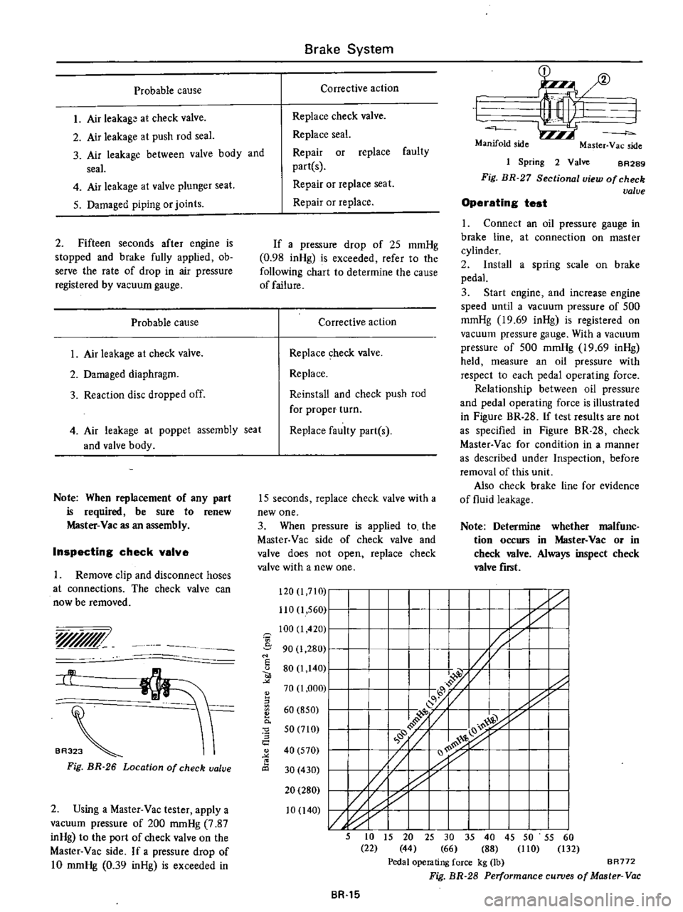
Operating
test
1
Connect
an
oil
pressure
gauge
in
brake
line
at
connection
on
master
cylinder
2
Install
a
spring
scale
on
brake
pedal
3
Start
engine
and
increase
engine
speed
until
a
vacuum
pressure
of
500
mmHg
19
69
inHg
is
registered
on
vacuum
pressure
gauge
With
a
vacuum
pressure
of
500
mmHg
19
69
inHg
held
measure
an
oil
pressure
with
respect
to
each
pedal
operating
force
Relationship
between
oil
pressure
and
pedal
operating
force
is
illustrated
in
Figure
BR
28
If
test
results
are
not
as
specified
in
Figure
BR
28
check
Master
Vac
for
condition
in
a
manner
as
described
under
Inspection
before
removal
of
this
unit
Also
check
brake
line
for
evidence
of
fluid
leakage
Note
Determine
whether
malfunc
tion
occurs
in
Master
Vac
or
in
check
valve
Always
inspect
check
valve
fiTlit
Page 392 of 537

BA1Bl
Fig
BR
36
Remouing
ualue
operating
rod
assembly
4
Withdraw
reaction
disc
BA286
Fig
BR
37
Remouing
reaction
disc
Front
shell
seal
I
Detach
flange
from
front
shell
assembly
BR287
g
Fig
BR
38
Removing
lange
2
Withdraw
front
seal
assembly
INSPECTION
I
Check
poppet
assembly
for
condi
tion
If
it
shows
evidence
of
wear
or
damage
replace
it
and
valve
operating
rod
assembly
2
Check
other
component
parts
for
condition
If
any
part
shows
evidence
of
wear
or
damage
replace
it
with
a
new
one
Brake
System
ASSEMBLY
AND
ADJUSTMENT
Assemble
in
the
reverse
sequence
of
disassembly
Rear
shell
seal
1
Apply
a
coating
of
Master
Vac
grease
to
the
sealing
surface
and
lip
of
seal
and
install
that
seal
in
rear
shell
with
the
use
of
Master
Vac
Oil
Seal
Retainer
Drift
ST08060000
Fig
BR
39
Installing
oil
seal
Note
Referring
to
Figure
BR
40
in
stall
seal
in
place
by
properly
aligning
the
pawl
of
special
tool
with
seal
hole
Adjustment
is
cor
rect
when
specified
length
at
A
is
obtained
Length
A
6
7
to
7
Omm
0
264
to
0
276
in
BA1S5
Fig
BR
40
Length
at
A
Diaphragm
plate
I
Apply
a
thin
coating
of
grease
to
the
sliding
contact
portion
on
the
periphery
of
plunger
assembly
BR
17
1
SR1S6
Fig
BR
41
Requiring
grease
place
2
Install
plunger
assembly
and
silencer
in
diaphragm
plate
and
lightly
push
plunger
stop
key
in
place
Note
Diaphragm
plate
is
made
of
bakelite
Exercise
care
in
instaJJing
plunger
assembly
not
to
damage
diaphragm
plate
BROB3
Fig
BR
42
Inserting
stop
key
3
Before
installing
diaphragm
into
position
apply
a
thin
coating
of
mica
power
to
it
except
outer
diameter
and
seating
portion
with
which
shell
comes
into
contact
4
Before
installing
reaction
disc
in
place
on
diaphragm
plate
apply
a
thin
coating
of
Master
Vac
grease
Front
shell
seal
Before
installing
front
shell
seal
as
sembly
apply
a
coating
of
Master
Vac
grease
to
the
inner
wall
of
seal
and
front
sheU
with
which
seal
comes
into
contact
Final
sssembly
Apply
thin
coating
of
Master
Vac
grease
to
the
outer
edges
of
diaphragm
with
which
rear
and
front
shells
come
into
contact
before
instaIling
dia
phragm
in
position
2
Before
installing
push
rod
assem
bly
in
place
apply
a
coating
of
Master
Vac
grease
to
the
sliding
con
tact
surface
of
diaphragm
plate
Page 394 of 537
1
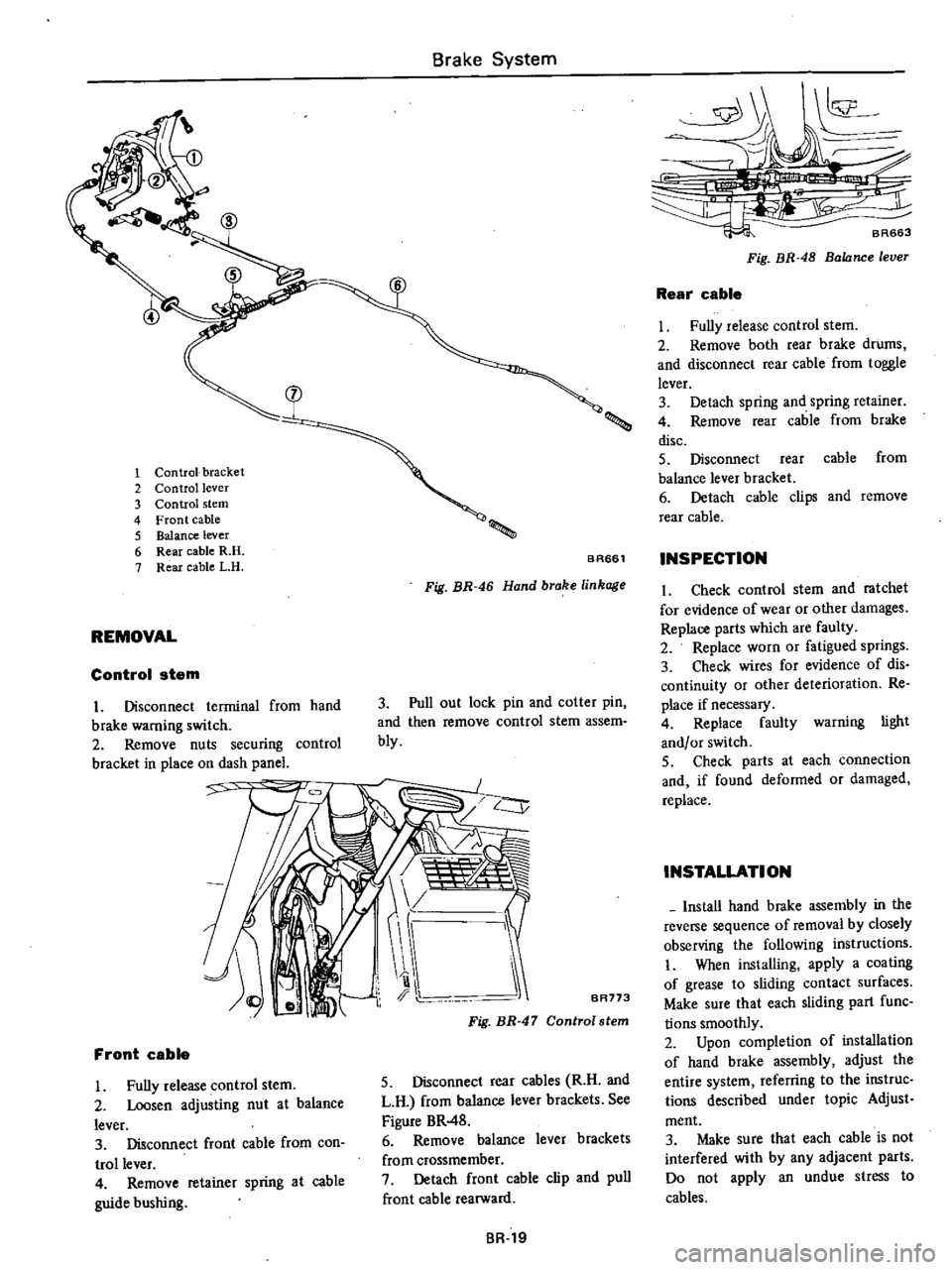
Control
bracket
2
Control
lever
3
Control
stem
4
Front
cable
5
Balance
lever
6
Rear
cable
R
H
7
Rear
cable
L
H
REMOVAL
Control
stem
I
Disconnect
terminal
from
hand
brake
warning
switch
2
Remove
nuts
securing
control
bracket
in
place
on
dash
panel
Brake
System
BAS6l
Fig
BR
46
Hand
brake
linkage
3
Pull
out
lock
pin
and
colter
pin
and
then
remove
control
stem
assem
bly
y
J
b
i1
I
I
1
II
i
l
I
BR773
Front
cable
Fully
release
control
stem
2
Loosen
adjusting
nut
at
balance
lever
3
Disconnect
front
cable
from
con
trollever
4
Remove
retainer
spring
at
cable
guide
bushing
Fig
BR
47
Control
stem
5
Disconnect
rear
cables
R
H
and
L
H
from
balance
lever
brackets
See
Figure
BR
48
6
Remove
balance
lever
brackets
from
crossmember
7
Detach
front
cable
clip
and
pull
front
cable
rearward
BR
19
k
1
BR663
Fig
BR
48
Balance
lever
Rear
cable
Fully
release
control
stem
2
Remove
both
rear
brake
drums
and
disconnect
rear
cable
from
toggle
lever
3
Detach
spring
and
spring
retainer
4
Remove
rear
cable
from
brake
disc
5
Disconnect
rear
cable
from
balance
lever
bracket
6
Detach
cable
clips
and
remove
rear
cable
INSPECTION
1
Check
control
stem
and
ratchet
for
evidence
of
wear
or
other
damages
Replace
parts
which
are
faulty
2
Replace
worn
or
fatigued
springs
3
Check
wires
for
evidence
of
dis
continuity
or
other
deterioration
Re
place
if
necessary
4
Replace
faulty
warning
light
and
or
switch
S
Check
parts
at
each
connection
and
if
found
deformed
or
damaged
replace
INSTALLATION
Install
hand
brake
assembly
in
the
reverse
sequence
of
removal
by
closely
observing
the
following
instructions
When
installing
apply
a
coating
of
grease
to
sliding
contact
surfaces
Make
Sure
that
each
sliding
part
func
lions
smoothly
2
Upon
completion
of
installation
of
hand
brake
assembly
adjust
the
entire
system
referring
to
the
instruc
lions
described
under
topic
Adjust
ment
3
Make
sure
that
each
cable
is
not
interfered
with
by
any
adjacent
parts
Do
not
apply
an
undue
stress
to
cables
Page 397 of 537
Condition
Excessive
pedal
travel
Spongy
pedal
Poor
braking
effect
Brakes
drag
Brake
Syst
em
TROUBLE
DIAGNOSES
AND
CORRECTIONS
Probable
cause
Low
brake
1uid
level
or
empty
master
cylinder
reservoir
Leakage
in
master
cylinder
Deteriorated
check
valve
Air
in
system
Faulty
brake
adjustment
Low
1uid
level
in
master
cylinder
Air
in
system
Faulty
brake
adjustment
Reservoir
filler
cap
vent
hole
clogged
Swollen
hose
due
to
deterioration
or
use
of
poor
quality
hose
Distorted
brake
shoes
or
excessively
worn
or
cracked
brake
drum
Soft
or
swollen
caliper
seals
Use
of
a
brake
1uid
with
too
low
boiling
point
Fluid
leakage
in
brake
lines
Low
brake
1uid
level
or
empty
master
cylinder
reservoir
Air
in
brake
lines
Excessive
shoe
ta
drum
clearance
Grease
oil
mud
or
water
on
linings
or
pads
Deterioration
of
linings
or
pads
Local
fit
of
linings
or
pads
Linings
or
pads
excessively
worn
Master
cylinder
or
wheel
cylinders
in
poor
condition
Binding
mechanical
linkage
at
brake
pedal
and
shoes
Clogged
brake
lines
Incorrect
adjustment
of
wheel
bearings
Improper
shoe
t
drum
clearance
Weak
shoe
return
springs
No
free
travel
in
brake
shoe
return
BR
22
Corrective
action
Fill
and
bleed
as
necessary
Test
for
source
of
leakage
by
examining
all
lines
connec
tions
and
wheel
cylinder
Overhaul
master
cylinder
Replace
check
valve
and
bleed
system
Bleed
system
Adjust
shoe
to
drum
clearance
Inspect
auto
adjuster
operation
Top
with
1uid
and
inspect
for
leakage
Correct
as
necessary
Adjust
shoe
to
drum
clearance
Inspect
aut
adjuster
operation
Clean
and
bleed
system
Replace
hose
and
bleed
system
Replace
faulty
parts
Drain
hydraulic
system
flush
with
alcohol
and
replace
all
seals
Replace
with
specified
brake
1uid
and
bleed
system
Check
master
cylinder
pIpIng
and
wheel
cylinder
for
leaks
and
repair
Fill
and
bleed
as
necessary
Bleed
system
Adjust
Clean
brake
mechanism
and
check
for
cause
of
problem
Replace
linings
or
pads
Replace
Shave
or
replace
Replace
Repair
or
replace
Free
up
as
required
Check
and
clean
Adjust
or
repair
Adjust
Replace
Adjust
pedal
height
Page 398 of 537

Condition
Brake
chatters
Brake
squeals
Pedal
pulsates
Brakes
fade
Brakes
drag
Unbalanced
brakes
Brake
System
Probable
cause
Groove
or
out
of
round
brake
drum
Loose
or
bent
brake
disc
Distorted
brake
shoes
or
pads
Grease
or
brake
fluid
on
linings
Dirty
or
scored
brake
drums
Distorted
brake
shoes
or
bent
support
plate
Weak
or
broken
brake
shoe
retaining
spring
or
return
spring
Glazed
or
contaminated
brake
lining
Out
of
round
or
off
center
drum
Brake
fluid
has
too
low
boiling
point
Use
of
improper
linings
or
brake
linings
are
contaminated
Brake
drums
are
out
of
round
Hydraulic
connections
master
cylinder
and
wheel
cylinders
are
corroded
or
damaged
Bleed
screw
is
open
Pedal
linkage
is
binding
or
push
rod
adjust
ment
is
too
long
Master
cylinder
compensator
part
is
ob
structed
Seized
master
cylinder
piston
Poor
shoe
condition
Poor
wheel
cylinder
condition
Deformation
of
piston
cups
Hand
brake
will
not
return
Clogged
master
cylinder
return
port
Improper
tire
inflation
Improper
adjustment
of
shoe
to
drum
clear
anee
Grease
oil
mud
or
water
on
linings
or
pads
Mud
in
brake
drum
Deterioration
of
linings
or
pads
Excessive
wear
of
linings
or
pads
BR
23
Corrective
action
Grind
or
replace
as
required
Tighten
support
plate
bolts
to
specified
torque
or
replace
plate
Replace
as
necessary
Replace
linings
Blowout
assembly
with
compressed
air
or
refinish
drum
Replace
faulty
unit
Replace
if
faulty
Cam
ground
lining
to
eliminate
glaze
If
it
doesn
t
replace
linings
Turn
drum
or
replace
as
necessary
Drain
and
fill
system
with
approved
fluid
Replace
linings
Repair
or
replace
as
necessary
Repair
as
necessary
Close
screw
and
bleed
system
Lubricate
linkage
check
pedal
return
spring
for
condition
and
adjust
push
rod
as
neces
sary
Blowout
foreign
matter
with
compressed
air
Disassemble
master
cylinder
and
replace
piston
Bleed
system
Clean
and
repair
Repair
or
replace
Replace
Check
and
repair
Clean
Inflate
to
correct
pressure
Readjust
Clean
brake
mechanism
and
check
for
cause
of
problem
Replace
linings
or
pads
Clean
Replace
Replace
Page 399 of 537

Condition
Pedal
yields
under
slight
pressure
Brake
System
Probable
cause
Wheel
cylinder
in
poor
condition
Poor
sliding
condition
of
brake
shoe
Looseness
of
cylinder
body
or
back
plate
securing
bolts
Scored
or
out
of
round
drums
Sticking
wheel
cylinder
cups
Deformation
of
back
plate
Incorrect
adjustment
of
wheel
bearings
Incorrect
adjustment
of
wheel
alignment
Looseness
of
leaf
spring
securing
U
bolts
Faulty
N
L
S
V
Deteriorated
check
valve
Ex
ternalleaks
Leakage
on
master
cylinder
BR
24
Corrective
action
Repair
or
replace
Adjust
Fasten
or
replace
Recondition
or
replace
brake
drum
as
reo
quired
Check
for
improper
lining
contact
with
drum
and
grind
lining
if
necessary
Recondition
or
replace
cylinder
Replace
Adjust
or
replace
Adjust
Tighten
or
replace
Replace
Replace
check
valve
and
bleed
system
Check
master
cylinder
piping
and
wheel
cylinder
for
leaks
and
repair
Overhaul
master
cylinder
Page 402 of 537
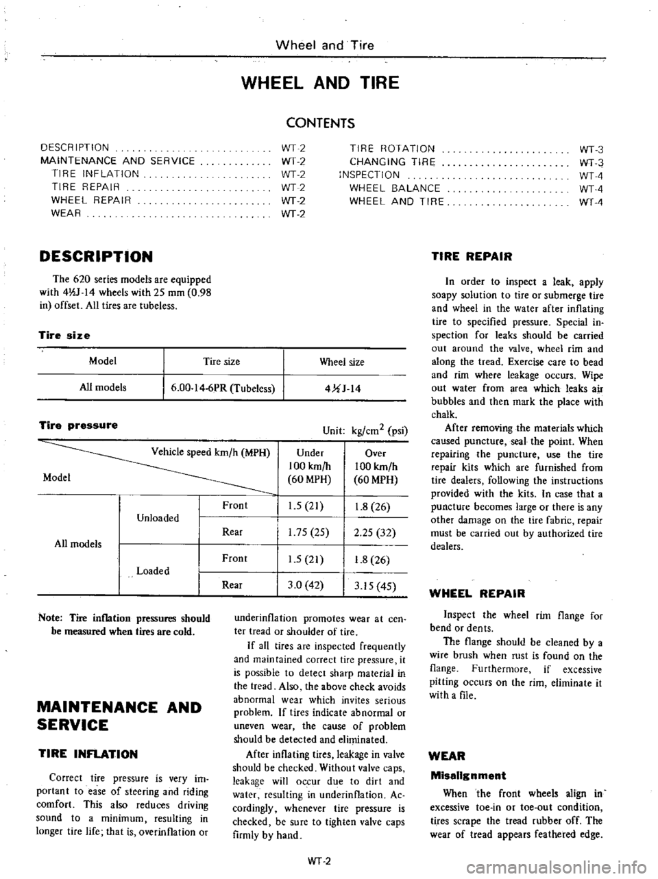
DESCRIPTION
MAINTENANCE
AND
SERVICE
TIRE
INFLATION
TIRE
REPAIR
WHEEL
REPAIR
WEAR
DESCRIPTION
The
620
series
models
are
equipped
with
4lV
14
wheels
with
25
mOl
0
98
in
offset
All
tires
are
tubeless
Wheel
and
Tire
WHEEL
AND
TIRE
CONTENTS
WT2
WT
2
WT2
WT2
WT
2
WT
2
TIRE
ROTATION
CHANGING
TIRE
INSPECTION
WHEEL
BALANCE
WHEEL
AND
TIRE
Tire
size
Model
Tire
size
Wheel
size
All
models
6
00
I
4
6PR
Tubeless
4UJ
14
Tire
pressure
Unit
kgl
em
2
psi
Vehicle
speed
km
h
MPH
Under
Over
100
km
h
100
km
h
Model
60
MPH
60
MPH
Front
1
5
21
1
8
26
Unloaded
Rear
175
25
2
25
32
All
models
Front
1
5
21
1
8
26
Loaded
Rear
3
0
42
3
15
4S
Note
Tire
inflation
pressures
should
be
measured
when
tires
are
cold
MAINTENANCE
AND
SERVICE
TIRE
INFLATION
Correct
tire
pressure
is
very
im
portant
to
ease
of
steering
and
riding
comfort
This
also
reduces
driving
sound
to
a
minimum
resulting
in
longer
tire
life
that
is
overinflation
or
underinflation
promotes
wear
at
cen
ter
tread
or
shouider
of
tire
If
aU
tires
are
inspected
frequently
and
maintained
correct
tire
pressure
it
is
possible
to
detect
sharp
material
in
the
tread
Also
the
above
check
avoids
abnormal
wear
which
invites
serious
problem
If
tires
indicate
abnormal
or
uneven
wear
the
cause
of
problem
should
be
detected
and
eliminated
After
inflating
tires
leakage
in
valve
should
be
checked
Without
valve
caps
leakage
will
occur
due
to
dirt
and
water
resulting
in
underinflation
Ac
cordingly
whenever
tire
pressure
is
checked
be
sure
to
tighten
valve
caps
firmly
by
hand
WT
2
WT3
WT3
WTA
WTA
WT
4
TIRE
REPAIR
In
order
to
inspect
a
leak
apply
soapy
solution
to
tire
or
submerge
tire
and
wheei
in
the
water
after
inflating
tire
to
specified
pressure
Special
in
spection
for
leaks
should
be
carried
out
around
the
valve
wheel
rim
and
along
the
tread
Exercise
care
to
bead
and
rim
where
leakage
occurs
Wipe
out
water
from
area
which
leaks
air
bubbles
and
then
mark
the
place
with
chalk
After
removing
the
materials
which
caused
puncture
seal
the
point
When
repairing
the
puncture
use
the
tire
repair
kits
which
are
furnished
from
tire
dealers
following
the
instructions
provided
with
the
kits
In
case
that
a
puncture
becomes
large
or
there
is
any
other
damage
on
the
tire
fabric
repair
must
be
carried
out
by
authorized
tire
dealers
WHEEL
REPAIR
Inspect
the
wheel
rim
flange
for
bend
or
dents
The
flange
should
be
cleaned
by
a
wire
brush
when
rust
is
found
on
the
flange
Furthermore
if
excessive
pitting
occurs
on
the
rim
eliminate
it
with
a
file
WEAR
Missilgnment
When
the
front
wheels
align
in
excessive
toe
in
or
toe
out
condition
tires
scrape
the
tread
rubber
off
The
wear
of
tread
appears
feathered
edge
Page 404 of 537
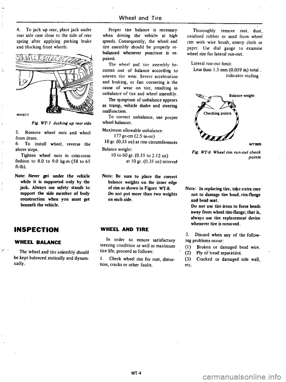
4
To
jack
up
rear
place
jack
under
rear
axle
case
close
to
the
side
of
rear
spring
after
applying
parking
brake
and
blocking
front
wheels
WH077
Fig
WT
7
Jacking
up
rear
side
S
Remove
wheel
nuts
and
wheel
from
drum
6
To
install
wheel
reverse
the
above
steps
Tighten
wheel
nuts
in
criss
cross
fashion
to
8
0
to
9
0
kg
m
S8
to
6S
ft
Ib
Note
Nerer
get
under
the
vehicle
while
it
is
supported
only
by
the
jack
Always
use
S8
fety
stands
to
support
the
side
member
of
body
construction
when
you
must
get
beneath
the
vehicle
INSPECTION
WHEEL
BALANCE
The
wheel
arid
tire
asSembly
should
be
kept
balanced
statically
and
dynam
ically
Wheel
and
Tire
Proper
tire
balance
is
necessary
when
driving
the
vehicle
at
high
speeds
Consequently
the
wheel
and
tire
assembly
should
be
properly
re
balanced
whenever
puncture
is
re
paired
The
wheel
and
tire
assembly
be
comes
out
of
ba1ance
according
to
uneven
tire
wear
Severe
acceleration
and
braking
or
fast
cornering
is
the
cause
of
wear
on
tire
resulting
in
unbalance
of
tire
and
wheel
assembly
The
symptom
of
unbalance
appears
as
tramp
vehicle
shake
and
steering
malfunction
To
correct
unbalance
use
proper
wheel
balancer
Maximum
allowable
unbalance
177
gr
cm
2
5
in
oz
10
gr
O
3S
oz
at
rim
circumferences
Balance
weight
10
to
60
gr
O
3S
to
2
12
oz
at
10
gr
0
3S
oz
intervat
Note
Be
sure
to
place
the
correct
balance
weights
on
the
inner
edge
of
rim
as
shown
in
Figure
WT
S
00
not
put
more
than
two
weights
on
each
side
WHEEL
AND
TIRE
In
order
to
ensure
satisfactory
steering
condition
as
well
as
maximum
tire
life
proceed
as
follows
Check
wheel
rim
for
rust
distor
tion
cracks
or
other
faults
WT
4
Thoroughly
remove
rust
dust
oxidized
rubber
or
sand
from
wheel
rim
with
wire
brush
emery
cloth
or
paper
Use
dial
gauge
to
examine
wheel
rim
for
lateral
run
out
Lateral
run
Qut
limit
Less
tltan
1
5
mOl
0
059
il
total
indicator
reading
WTOO5
Fig
WT
B
Whetl
rim
run
out
check
points
Note
In
replacing
tire
t
e
extra
care
not
to
damage
tire
bead
rim
flange
and
bead
seat
Do
not
use
tire
irons
to
force
beads
away
from
wheel
rim
flange
that
is
always
use
tire
replacement
device
whenever
tire
is
removed
2
Discard
when
any
of
the
follow
ing
problems
occur
1
Broken
or
damaged
bead
wire
2
Ply
o
treairsepanitiori
3
Cracked
or
damaged
side
wall
etc
Page 410 of 537
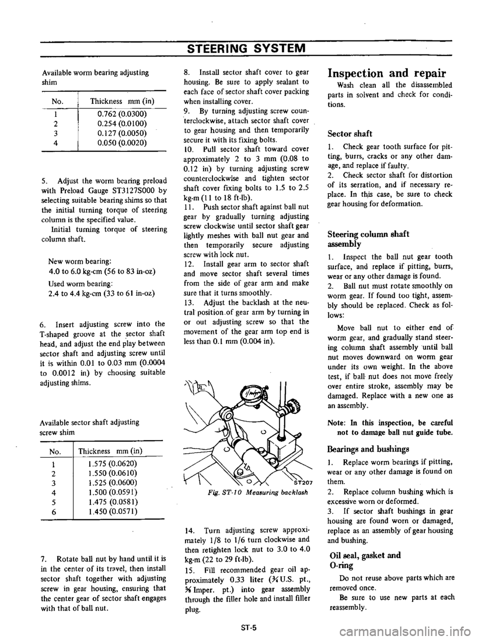
Available
worm
bearing
adjusting
shim
No
Thickness
mOl
in
I
0
762
0
0300
2
0
2S4
0
0100
3
0
127
0
0050
4
O
OSO
0
0020
5
Adjust
the
worm
bearing
preload
with
Preload
Gauge
ST3127S000
by
selecting
suitable
bearing
shims
so
that
the
initial
turning
torque
of
steering
column
is
the
specified
value
Initial
turning
torque
of
steering
column
shaft
New
worm
bearing
4
0
to
6
0
kg
em
S6
to
83
in
oz
Used
worm
bearing
2
4
to
4
4
kg
em
33
to
61
in
oz
6
Insert
adjusting
screw
into
the
T
shaped
groove
at
the
sector
shaft
head
and
adjust
the
end
play
between
sector
shaft
and
adjusting
screw
until
it
is
within
0
01
to
0
03
mm
0
0004
to
0
0012
in
by
choosing
suitable
adjusting
shims
Available
sector
shaft
adjusting
screw
shim
No
Thickness
mOl
in
I
1
57S
0
0620
2
1
550
0
0610
3
1
525
0
0600
4
I
S00
0
OS91
S
1
475
0
0581
6
I
4S0
0
0571
7
Rotate
ball
nut
by
hand
until
it
is
in
the
center
of
its
trovel
then
install
sector
shaft
together
with
adjusting
screw
in
gear
housing
ensuring
that
the
center
gear
of
sector
shaft
engages
with
that
of
ball
nut
STEERING
SYSTEM
8
Install
sector
shaft
cover
to
gear
housing
Be
sure
to
apply
sealant
to
each
face
of
sector
shaft
cover
packing
when
installing
cover
9
By
turning
adjusting
screw
coun
terclockwise
attach
sector
shaft
cover
to
gear
housing
and
then
temporarily
secure
it
with
its
fixing
bolts
10
Pull
sector
shaft
toward
cover
approximately
2
to
3
mOl
0
08
to
0
12
in
by
turning
adjusting
screw
counterclockwise
and
tighten
sector
shaft
cover
fixing
bolts
to
l
S
to
2
5
kg
m
11
to
18
ft
Ib
II
Push
sector
shaft
against
ball
nut
gear
by
gradually
turning
adjusting
screw
clockwise
until
sector
shaft
gear
lightly
meshes
with
ball
nut
gear
and
then
temporarily
secure
adjusting
screw
with
lock
nut
12
Install
gear
arm
to
sector
shaft
and
move
sector
shaft
several
times
from
the
side
of
gear
arm
and
make
sure
that
it
turns
smoothly
13
Adjust
the
backlash
at
the
neu
tral
position
of
gear
arm
by
turning
in
or
out
adjusting
screw
so
that
the
movement
of
the
gear
arm
top
end
is
less
than
0
1
mOl
0
004
in
0
ST207
Fig
ST
10
Mea
uring
backlash
14
Turn
adjusting
screw
approxi
mately
1
8
to
1
6
turn
clockwise
and
then
retighten
lock
nut
to
3
0
to
4
0
kg
m
22
to
29
ft
Ib
IS
Fill
recommended
gear
oil
ap
proximately
0
33
liter
X
U
S
pI
X
Imper
pt
into
gear
assembly
through
the
filler
hole
and
install
filler
plug
ST
5
Inspection
and
repair
Wash
clean
all
the
disassembled
parts
in
solvent
and
check
for
condi
tions
Sector
shaft
1
Check
gear
tooth
surface
for
pit
ting
burrs
cracks
or
any
other
dam
age
and
replace
if
faulty
2
Check
sector
shaft
for
distortion
of
its
serration
and
if
necessary
re
place
In
this
case
be
sure
to
check
gear
housing
for
deformation
Steering
column
shaft
assembly
1
Inspect
the
ball
nut
gear
tooth
surface
and
replace
if
pitting
burrs
wear
or
any
other
damage
is
found
2
Ball
nut
must
rotate
smootWy
on
worm
gear
If
found
too
tight
assem
bly
should
be
replaced
Check
as
fol
lows
Move
ball
nut
to
either
end
of
worm
gear
and
gradually
stand
steer
ing
column
shaft
assembly
until
ball
nut
moves
downward
on
worm
gear
under
its
own
weight
In
the
above
test
if
ball
nut
does
no
move
freely
over
entire
stroke
assembly
may
be
damaged
Replace
with
a
new
one
as
an
assembly
Note
In
this
inspection
be
careful
not
to
dama
e
ball
nut
guide
tube
Bearings
and
bushings
I
Replace
worm
bearings
if
pitting
wear
or
any
other
damage
is
found
on
them
2
Repiace
column
bushing
which
is
excessive
worn
or
deformed
3
If
sector
shaft
bushings
in
gear
housing
are
found
worn
or
damaged
replace
as
an
assembly
of
gear
housing
and
bushing
Oil
seal
gasket
and
O
ring
Do
not
reuse
above
parts
which
are
removed
once
Be
sure
to
use
new
parts
at
each
reassembly