check DATSUN PICK-UP 1977 Service Manual
[x] Cancel search | Manufacturer: DATSUN, Model Year: 1977, Model line: PICK-UP, Model: DATSUN PICK-UP 1977Pages: 537, PDF Size: 35.48 MB
Page 447 of 537
DESCRIPTION
Cables
are
covered
with
color
coded
vinyl
for
easy
identification
In
the
wiring
diagram
colors
are
indicated
by
one
or
two
alphabetical
letters
It
is
recommended
that
the
battery
be
disconnected
before
performing
any
electrical
service
other
than
bulb
or
fuse
replacement
In
addition
to
fuses
a
fusible
link
has
been
installed
to
protect
wiring
The
fusible
link
functions
almost
the
same
as
a
fuse
though
its
eharac
teristics
are
slightly
different
than
normal
fuses
CABLE
COLORS
Cable
colors
are
indicated
by
one
or
two
alphabetical
letters
B
Black
Be
Brown
G
Green
L
Blue
Lg
Light
green
R
Red
W
White
Y
Yellow
The
main
cable
is
generally
coded
with
a
single
color
The
others
are
coded
with
a
two
tone
color
as
follows
BW
Black
with
white
stripe
gR
Light
green
with
red
stripe
INSPECTION
Inspect
all
electrical
circuits
refer
ring
to
wiring
or
circuit
diagrams
Circuits
should
be
tested
for
conti
nuity
or
short
circuit
with
a
conven
tional
test
lamp
or
low
reading
volt
meter
Before
inspection
of
circuit
ensure
that
I
Each
electrical
component
part
or
cable
is
securely
fastened
to
its
con
nector
or
terminal
2
Each
connection
is
firmly
in
place
and
free
from
rust
and
dirt
3
No
cable
covering
shows
any
evidence
of
cracks
deterioration
or
other
damage
4
Each
terminal
is
at
a
safe
distance
away
from
any
adjacent
metal
parts
5
Each
cable
is
fastened
to
its
proper
connector
or
terminal
Body
Electrical
System
BODY
ELECTRICAL
WIRING
6
Each
grounding
bolt
is
firmly
pbnted
7
Wiring
is
kept
away
from
any
adjacent
parts
with
sharp
edges
or
high
temperature
parts
such
as
exhaust
pipe
8
Wiring
is
kept
away
from
any
rotating
or
working
parts
fan
pulley
fan
belt
etc
9
Cables
between
ftxed
portions
and
moving
parts
are
long
enough
to
withstand
shocks
and
vibratory
forces
Notes
a
Before
starting
to
inspect
and
repair
any
part
of
electrical
system
or
other
parts
which
may
lead
to
a
short
circuit
disconnect
cables
at
battery
terminals
as
follows
Disconnect
cable
at
negative
terminal
and
then
disconnect
cable
at
positive
terminal
Before
connecting
cables
to
battery
terminal
be
sure
to
clean
terminals
with
a
rag
Fasten
cable
at
positive
terminal
and
then
ground
cable
at
negative
terminal
Apply
grease
to
top
of
these
terminals
to
prevent
rust
from
developing
on
them
b
Never
use
a
screwdriver
or
senrice
tool
to
conduct
a
continuity
test
Use
test
leads
c
Never
ground
an
open
circuit
or
circuits
under
no
load
Use
a
test
lamp
12V
3W
or
circuit
tester
as
a
load
FUSE
AND
FUSIBLE
LINK
DESCRIPTION
The
fuse
and
fusible
link
are
protec
tive
devices
used
in
an
electrical
cir
cuit
When
current
increases
beyond
rated
amperage
fusible
metal
melts
and
the
circuit
is
broken
BE
2
MAINTENANCE
INSTRUCTIONS
Fuse
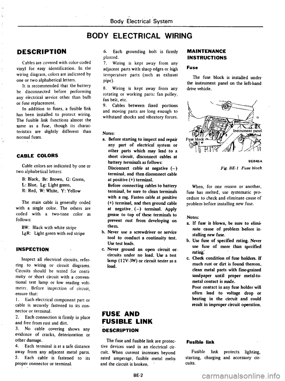
The
fuse
block
is
installed
under
the
instrument
panel
on
the
left
hand
drive
vehicle
BE848A
Fig
BE
1
Fuse
block
When
for
one
reason
or
another
fuse
has
melted
use
systematic
pro
cedure
to
check
and
eliminate
cause
of
problem
before
installing
new
fuse
Notes
a
If
fuse
is
blown
be
sure
to
elimi
nate
cause
of
problem
before
in
stalling
new
fuse
b
Use
fuse
of
specified
rating
Never
use
fuse
of
more
than
specified
rating
Co
Check
condition
of
fuse
holders
If
much
rust
or
dirt
is
found
thereon
clean
metal
parts
with
fine
grained
sandpaper
until
proper
metal
to
metal
contact
is
made
Poor
contact
in
any
fuse
holder
will
often
lead
to
voltage
drop
or
heating
in
the
circuit
and
could
result
in
improper
circuit
operation
Fusible
link
Fusible
link
protects
lighting
starting
charging
and
accessory
cir
cuits
Page 448 of 537

A
melted
fusible
link
can
be
de
tected
either
by
visual
inspection
or
by
feeling
with
finger
tip
If
its
condition
is
questionable
use
circuit
tester
or
test
lamp
as
required
to
conduct
continuity
test
This
continuity
test
can
be
performed
in
the
same
manner
as
for
any
conventional
fuse
Body
Electrical
System
Notes
a
If
fusible
link
should
melt
it
is
possible
that
critical
circuit
power
supply
or
large
current
carrying
circuit
is
shorted
In
such
a
case
carefully
check
and
eliminate
cause
of
problem
b
Never
wrap
periphery
of
fusible
link
with
vinyl
tape
Extreme
care
should
be
taken
with
this
link
to
ensure
that
it
does
not
come
into
contact
with
any
other
wiring
har
ness
or
vinyl
or
rubber
parts
c
BEB49A
Fig
BE
2
Fusible
link
LIGHTING
AND
SIGNAL
LAMP
SYSTEM
DESCRIPTION
LIGHTING
SYSTEM
CIRCUIT
DIAGRAM
HEADLAMP
HEAD
LAMP
BEAM
REPLACEMENT
AIMING
ADJUSTMENT
FRONT
COMBINATION
LAMP
BUL8
REPLACEMENT
REMOVAL
AND
INSTALLATION
SIDE
MARKER
LAMP
BUL8
REPLACEMENT
REMOVAL
AND
INSTALLATION
ROOM
LAMP
BULB
REPLACEMENT
REMOVAL
AND
INSTALLATION
REAR
COMBINATION
LAMP
BULB
REPLACEMENT
REMOVAL
AND
INSTALLATION
LICENSE
LAMP
BULB
REPLACEMENT
REMOVAL
AND
INSTALLATION
ENGINE
COMPARTMENT
LAMP
LIGHTING
SWITCH
REMOVAL
AND
INSTALLATION
INSPECTION
ILLUMINATION
CONTROL
RHEOSTAT
REMOVAL
AND
INSTALLATION
CONTENTS
BE
4
BE
4
BE
5
BE
5
BE
5
8E
7
BE
7
BE
7
8E
7
BE
7
8E
7
BE
8
BE
B
8E
8
BE
8
8E
8
8E
8
8E
8
BE
8
8E
8
BE
9
BE
9
BE
9
8E
9
8E
9
8E
9
INSPECTION
KN08
ILLUMINATION
LAMP
BULB
REPLACEMENT
LAMP
BODY
REPLACEMENT
TURN
SIGNAL
AND
DIMMER
SWITCH
REMOVAL
AND
INSTALLATION
INSPECTION
STOP
LAMP
SWITCH
REMOVAL
AND
INSTALLATION
INSPECTION
DOOR
SWITCH
REMOVAL
AND
INSTALLATION
INSPECTION
HAZARD
SWITCH
REMOVAL
AND
INSTALLATION
INSPECTION
FLASHER
UNIT
REPLACEMENT
8ULB
SPECIFICATIONS
TROUBLE
DIAGNOSES
AND
CORRECTIONS
HEAD
LAMP
TURN
SIGNAL
LAMP
TAIL
LAMP
STOP
LAMP
AND
BACK
UP
LAMP
BE
3
1
BE
9
BE
10
BE
10
BE10
BE
10
BE
10
BE
10
BE
10
BE
10
BE
10
BE
10
BE
10
BE
11
BE
11
BE
11
BE
11
8E
11
BE
11
BE
12
BE
12
BE
12
BE
13
8E
13
Page 457 of 537

Body
Electrical
System
BULB
SPECIFICATIONS
Item
Wattage
Candlepower
Headlamp
Inner
Outer
37
5W
37
5
S0W
Front
combination
lamp
Turn
signal
and
parking
lamp
23
8W
32
3C
Side
marker
lamp
Front
Rear
8W
4C
8W
4C
Rear
combination
lamp
Turn
signal
lamp
A
B
Tail
lamp
B
C
Stop
lamp
A
B
Back
up
lamp
D
A
23W
32C
B
23j8W
32j3C
C
8W
4C
D
23W
32C
7
SW
6C
License
plate
lamp
Engine
compartment
lamp
6W
Room
lamp
5W
Combination
meter
illurnina
tion
17W
iC
x3
Knob
illumination
lamp
3
4W
2C
Heater
control
illumination
lamp
3
4W
2C
TROUBLEDIAGNOSE
AND
CORRECTIONS
HEADLAMP
Condition
Headlarnps
do
not
light
for
both
high
and
low
beams
High
beam
cannot
be
switched
to
low
beam
or
vice
versa
Probable
cause
Burnt
fuse
Loose
connection
or
open
circuit
Faulty
lighting
switch
Faulty
dimmer
switch
Faulty
light
relay
No
ground
Faulty
dimmer
switch
Faulty
light
relay
BE12
Bulb
SAE
trade
number
4001
4002
1034
67
67
1073
1034
67
1073
89
161
158
158
Corrective
action
Correct
cause
and
replace
fuse
Check
wiring
and
or
repair
connection
Conduct
continuity
test
and
replace
if
neces
sary
Check
light
relay
for
proper
operation
and
replace
if
necessary
Clean
and
tighten
ground
terminal
Conduct
continuity
test
and
replace
if
neces
sary
Check
light
relay
for
proper
operation
and
replace
if
necessary
Page 458 of 537
Condition
Headiamps
dim
Headlamp
in
only
one
side
lights
TURN
SIGNAL
LAMP
Condition
Turn
signals
do
not
operate
Flashing
cycle
is
too
slow
Pilot
lamp
does
not
go
out
or
too
fast
Flashing
cycle
is
irregular
Body
Electrical
System
Probable
cause
Partly
discharged
or
faulty
battery
Faulty
charging
system
Poor
ground
or
loose
connection
Burnt
sealed
beams
Loose
headlamp
connection
Damaged
sealed
beam
Probable
cause
Burnt
fuse
Loose
connection
or
open
circuit
Faulty
flasher
unit
Faulty
turn
signal
switch
Bulbs
having
wattage
other
than
specified
wattage
are
used
Burnt
bulbs
Loose
connection
Inoperative
flasher
unit
Burnt
bulb
Loose
connection
Bulb
having
wattage
other
than
specified
wa
ttage
is
used
TAIL
LAMP
STOP
LAMP
AND
BACK
UP
LAMP
Condition
Both
right
and
left
lamps
do
not
light
Lamp
in
only
one
side
lights
Probable
cause
Burnt
fuse
Inoperative
stop
lamp
switch
Falllty
back
up
lamp
switch
Loose
connection
or
open
circuit
Burnt
bulb
Loose
bulb
BE13
Corrective
action
Measure
specific
gravity
of
electrolyte
and
recharge
or
replace
battery
if
necessary
Measure
voltage
at
headlamp
terminals
If
it
is
less
than
12
8V
check
charging
system
for
proper
operation
Clean
and
or
tighten
Replace
Repair
Replace
Corrective
action
Correct
cause
and
replace
Check
wiring
and
or
repair
connection
Replace
Conduct
continuity
test
and
replace
if
neces
sary
Replace
with
specified
one
Replace
Repair
Replace
Replace
Repair
Replace
with
specified
one
Corrective
action
Correct
cause
and
replace
Conduct
continuity
test
and
replace
if
neces
sary
Conduct
continuity
test
and
replace
if
neces
sary
Check
wiring
and
or
repair
connection
Replace
Repair
lamp
socket
Page 465 of 537
Condition
Fuel
gauge
Fuel
gauge
does
not
operate
Pointer
indicates
only
F
position
Body
Electrical
System
Probable
cause
Faulty
tank
unit
or
loose
unit
terminal
connection
pointer
indicates
a
half
level
when
a
35U
resistance
is
connected
between
tank
unit
yellow
wire
and
ground
Faulty
fuel
gauge
Poor
or
loose
cormection
Open
circuit
Faulty
tank
unit
pointer
lowers
below
E
mark
when
igni
tion
switch
Is
turned
off
Faulty
fuel
gauge
pointer
still
indicates
F
position
when
ignition
switch
is
turned
off
OIL
P
RESSURE
AND
CHARGE
WARNING
LAMPS
Condition
Oil
pressure
wamiug
lamp
Lamp
does
not
light
when
ignition
switch
is
set
to
ON
Lamp
does
not
go
out
while
engine
is
being
operated
OIarge
warning
lamp
Lamp
does
not
light
when
ignition
switch
is
set
to
ON
Lamp
does
not
go
out
when
engine
is
started
Probable
cause
Inoperative
oil
pressure
switch
or
loose
switch
terminal
connection
When
switch
yellow
black
wire
is
grounded
warning
lamp
lights
Burnt
bulb
or
loose
bulb
Open
circuit
Lack
of
engine
oil
Oil
pressure
too
low
Inoperative
oil
pressure
switch
Burnt
bulb
or
loose
bulb
Warning
lamp
does
not
light
when
voltage
regulator
white
red
wire
is
grounded
Open
circuit
Faulty
charging
system
BE
20
Corrective
action
Replace
tank
unit
or
correct
terminal
con
nection
Replace
fuel
gauge
Conect
connector
terminal
contact
Replace
tank
unit
Replace
fuel
gauge
Corrective
action
Replace
switch
OJ
correct
terminal
connee
tion
Replace
bulb
or
correct
bulb
socket
Check
oil
level
and
add
oil
as
required
Inspect
engine
oil
pressure
system
Replace
oil
pressure
switch
Replace
bulb
or
correct
bulb
socket
Inspect
charging
system
Page 469 of 537
Body
Electrical
System
tive
terminal
or
B
terminal
and
blue
red
wire
terminal
in
wiring
connector
plug
3
To
check
wiper
low
speed
opera
tion
connect
L
terminal
to
ground
with
ground
cable
or
connect
L
termi
nal
to
black
wire
terminal
make
sure
that
wipers
sweep
at
low
speed
4
To
check
wiper
high
speed
opera
tion
connect
ground
cable
to
H
termi
nal
in
the
same
manner
as
in
step
3
make
sure
that
wipers
sweep
fast
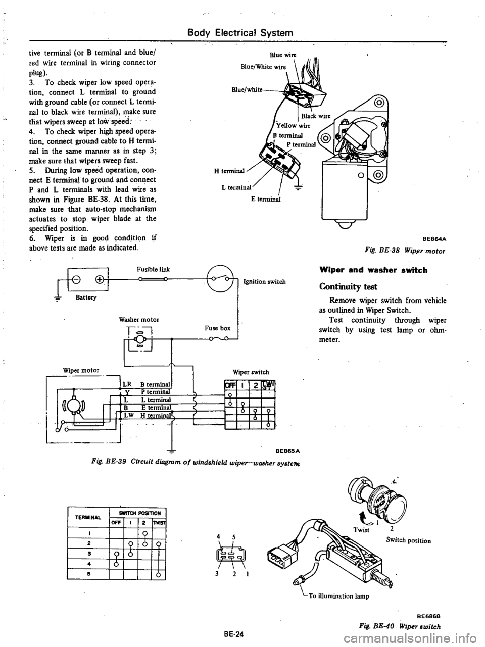
5
During
low
speed
operation
con
nect
E
terminal
to
ground
and
conl
ect
P
and
L
terminals
with
lead
wire
as
shown
in
Figure
BE
38
At
this
time
make
sure
that
auto
stop
mechanism
actuates
to
stop
wiper
blade
at
the
specified
position
6
Wiper
is
in
good
condition
if
above
tests
are
made
as
indicated
H
tenninal
Blue
white
o
@
C
BE864A
Fig
BE
38
Wipftrmotor
rt
Cl
Battery
Fusible
link
e
Ignition
witch
Wiper
and
washer
switch
I
D
j
Fuse
box
Y
O
Continuity
test
Remove
wiper
switch
from
vehicle
as
outlined
in
Wiper
Switch
Test
continuity
through
wiper
switch
by
using
test
lamp
or
ohm
meter
WQ5hcr
motor
Wiper
motor
191
LR
y
I
L
I
w
J
Wiper
switch
B
terminal
P
tenninal
L
terminal
E
terminal
H
t
rmjrW
r
21
1
b
I
r
1
I
I
BE865A
Fig
BE
39
Circuit
diagram
of
windshield
wiper
wtUher
sy
te7tl
TERMINAL
I
SlOIT01
POSIl10N
I
I
OFF
2
1
1
2
I
b
ii
4
5
Switch
position
2
I
Z
m
Z
I
I
I
I
I
I
I
10
I
3
2
BE686B
Fig
BE
40
Wi
r
witch
8E
24
Page 476 of 537
SEAT
BELT
WARNING
SYSTEM
DESCRIPTION
Except
Canada
When
the
ignition
switch
is
turned
to
the
ON
position
the
warning
lamp
comes
on
and
remains
on
for
4
to
8
seconds
The
warning
buzzer
sounds
for
4
to
8
seconds
intermittent
ly
if
the
driver
s
seat
belt
is
not
fastened
properly
The
seat
belt
warning
system
con
sists
of
a
driver
s
belt
switch
a
warning
buzzer
a
warning
lamp
a
timer
unit
and
an
ignition
switch
For
Canada
When
the
ignition
switch
is
turned
Body
Electrical
System
to
the
ON
position
the
warning
lamp
comes
on
and
the
warning
buz
zer
sounds
if
the
driver
s
seat
belt
is
not
fastened
properly
The
seat
belt
warning
system
con
sists
of
a
driver
s
belt
switch
a
warning
buzzer
a
warning
lamp
and
an
igni
tion
switch
REMOVAL
AND
INSTALLATION
Ignition
switch
Refer
to
page
BE
22
for
Removal
and
Installation
Timer
unit
Timer
unit
is
fIXed
on
a
reinforce
ment
behind
glove
box
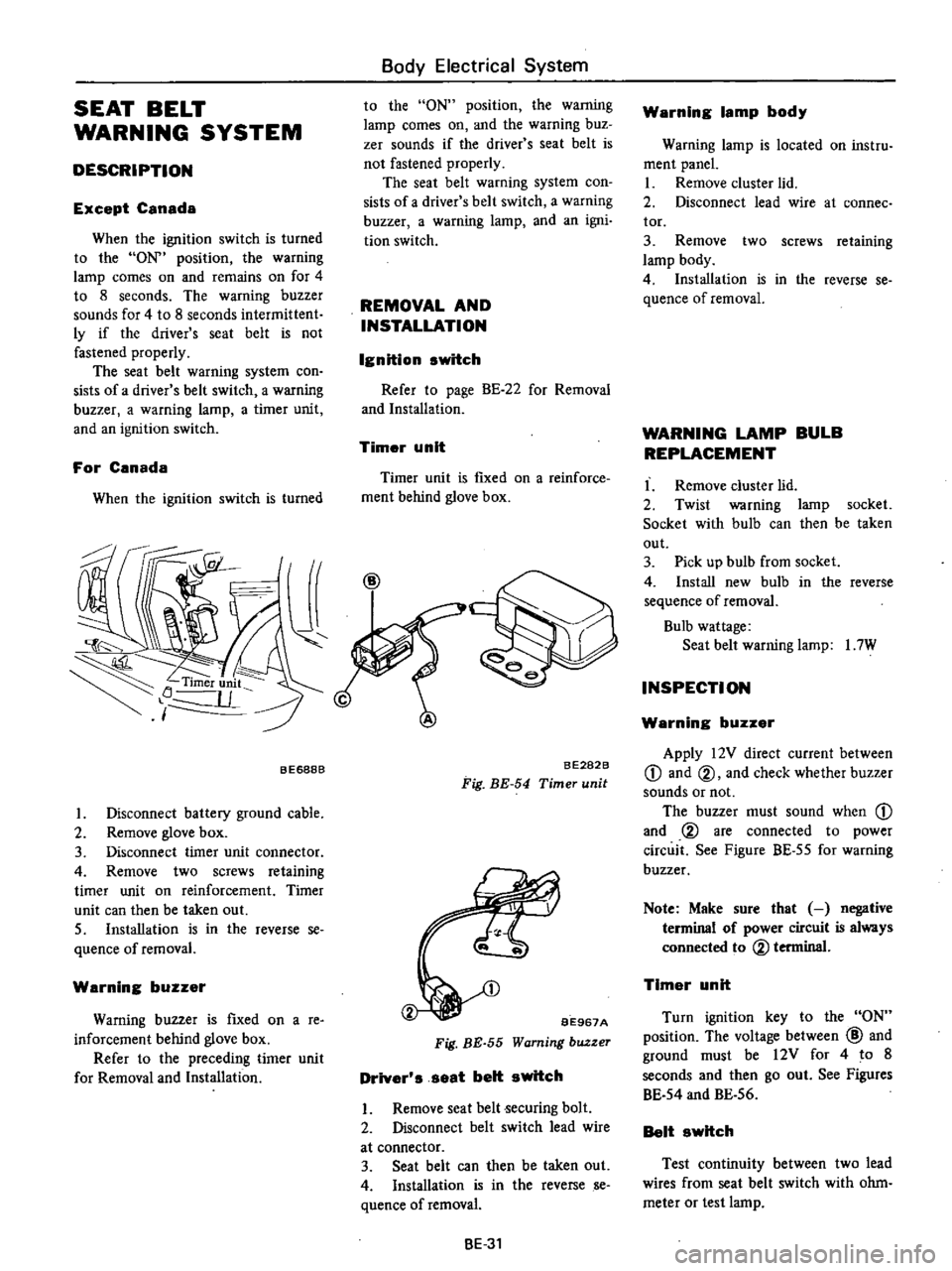
BE688B
I
Disconnect
battery
ground
cable
2
Remove
glove
box
3
Disconnect
timer
unit
connector
4
Remove
two
screws
retaining
timer
unit
on
reinforcement
Timer
unit
can
then
be
taken
out
S
Installation
is
in
the
reverse
se
quence
of
removal
Warning
buzzer
Warning
buzzer
is
fIxed
on
a
re
inforcement
behind
glove
box
Refer
to
the
preceding
timer
unit
for
Removal
and
Installation
BE282B
Fig
BE
54
Timer
unit
BE967A
Fig
BE
55
Warning
buzzer
Driver
s
seat
belt
switch
I
Remove
seat
belt
ecuring
bolt
2
Disconnect
belt
switch
lead
wire
at
connector
3
Seat
belt
can
then
be
taken
out
4
Installation
is
in
the
reverse
se
quence
ofremoval
BE
31
Warning
lamp
body
Warning
lamp
is
located
on
instru
ment
panel
I
Remove
cluster
lid
2
Disconnect
lead
wire
at
connee
tor
3
Remove
two
screws
retaining
lamp
body
4
Installation
is
in
the
reverse
se
quence
of
removal
WARNING
LAMP
BULB
REPLACEMENT
I
Remove
cluster
lid
2
Twist
warning
lamp
socket
Socket
with
bulb
can
then
be
taken
out
3
Pick
up
bulb
from
socket
4
Install
new
bulb
in
the
reverse
sequence
of
removal
Bulb
wattage
Seat
belt
warning
lamp
I
7W
INSPECTION
Warning
buzzer
Apply
12V
direct
current
between
CD
and
@
and
check
whether
buzzer
sounds
or
not
The
buzzer
must
sound
when
CD
and
@
are
connected
to
power
circuit
See
Figure
BE
55
for
warning
buzzer
Note
Make
sure
that
negative
terminal
of
power
circuit
is
always
connected
to
@
terminal
Timer
unit
Turn
ignition
key
to
the
ON
position
The
voltage
between
@
and
ground
must
be
12V
for
4
to
8
seconds
and
then
go
out
See
Figures
BE
54
and
BE
56
Belt
switch
Test
continuity
between
two
lead
wires
from
seat
belt
switch
with
ohm
meter
or
test
lamp
Page 479 of 537

Body
Electrical
System
WINDSHIELD
WIPER
AND
WASHER
Condition
Windshield
wiper
motor
does
not
operate
Wiper
operating
speed
is
too
slow
Wiper
speed
cannot
be
changed
correctly
Wiper
motor
continues
to
run
after
switch
is
turned
off
or
wiper
blades
do
not
return
to
correct
position
Probable
cause
Burnt
fuse
Damaged
motor
Check
wiper
motor
as
outlined
in
Inspec
tion
Loose
connection
Faulty
wiper
and
washer
switch
Test
continuity
through
switch
as
outlined
in
Inspection
Open
power
circuit
or
ground
circuit
Damaged
motor
Loose
or
poor
connection
Seized
or
rusted
wiper
linkage
Humming
occurs
on
motor
in
wiper
blade
operating
cycle
Wiper
blades
stick
on
windshield
glass
Raise
arm
and
operate
wiper
without
load
Faulty
wiper
switch
Damaged
motor
Faulty
auto
stop
operation
Poor
connection
Faulty
switch
BE
34
Corrective
action
Correct
cause
and
replace
fuse
Replace
wiper
motor
Repair
Replace
Repair
Replace
motor
Repair
Lubricate
or
replace
Clean
windshield
glass
and
or
replace
wiper
blade
Replace
Replace
Remove
auto
stop
device
cover
and
check
relay
contacts
Clean
dirty
contacts
or
repair
relay
plate
bending
if
necessary
Repair
Replace
Page 480 of 537
Body
Electrical
System
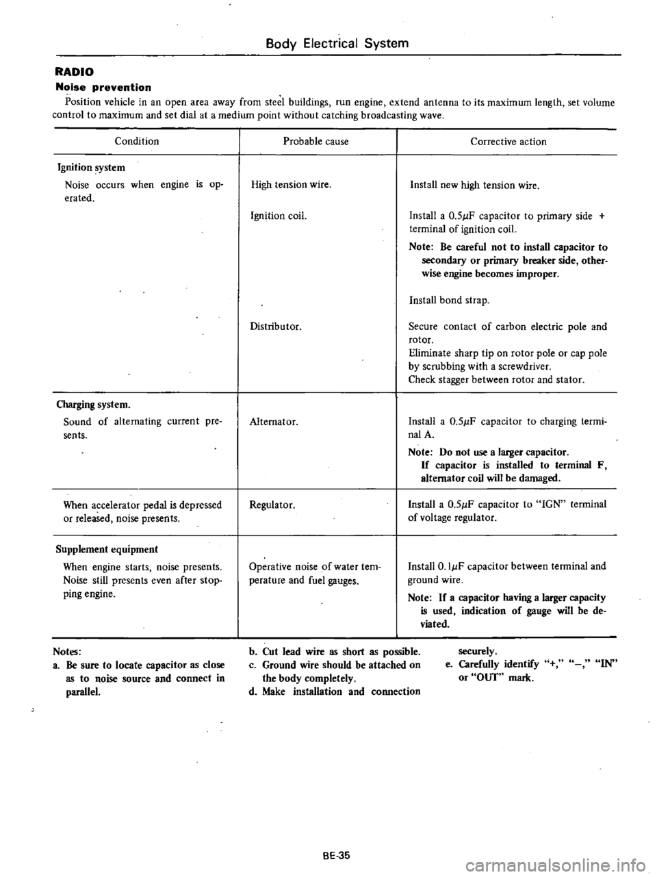
RADIO
Noise
prevention
Position
vehicle
in
an
open
area
away
from
steel
buildings
run
engine
extend
antenna
to
its
maximum
length
set
volume
control
to
maximum
and
set
dial
at
a
medium
point
without
catching
broadcasting
wave
Condition
Ignition
system
Noise
occurs
when
engine
is
op
erated
Charging
system
Sound
of
alternating
current
pre
sents
When
accelerator
pedal
is
depressed
or
released
noise
presents
Supplement
equipment
When
engine
starts
noise
presents
Noise
still
presents
even
after
stop
ping
engine
Notes
a
Be
sure
to
locate
capacitor
as
close
as
to
noise
source
and
connect
in
parallel
Probable
cause
Corrective
action
High
tension
wire
Install
new
high
tension
wire
Ignition
coil
Install
a
0
51lF
capacitor
to
primary
side
terminal
of
ignition
coil
Note
Be
careful
not
to
install
capacitor
to
secondary
or
primary
breaker
side
other
wise
engine
becomes
improper
Install
bond
strap
Distributor
Secure
contact
of
carbon
electric
pole
and
rotor
Eliminate
sharp
tip
on
rotor
pole
or
cap
pole
by
scrubbing
with
a
screwdriver
Check
stagger
between
rotor
and
stator
Alternator
Install
a
0
51lF
capacitor
to
charging
termi
nalA
Note
Do
not
use
a
larger
capacitor
If
capacitor
is
installed
to
terminal
F
alternator
coil
will
be
damaged
Regulator
Install
a
0
51lF
capacitor
to
IGN
terminal
of
voltage
regulator
Operative
noise
of
water
tem
perature
and
fuel
gauges
Install
O
IIlF
capacitor
between
terminal
and
ground
wire
Note
If
a
capacitor
having
a
larger
capacity
is
used
indication
of
gauge
will
be
de
viated
b
Cut
lead
wire
as
short
as
possible
c
Ground
wire
should
be
attached
on
the
body
completely
d
Make
installation
and
connection
securely
e
Carefully
identify
or
OUT
mark
IN
BE
35
Page 481 of 537

CD
m
Cl
@
D
@
I
j
1
To
instrument
harness
IS
To
battery
30
To
check
connector
2
To
full
transistor
amplifier
16
To
fusible
link
3t
To
headlamp
L
U
type
2
California
models
only
17
To
engine
harness
No
2
32
To
sido
marker
lamp
L
B
3
To
hood
switch
18
To
alternator
33
To
front
combination
lamp
L
H
4
To
engine
compartment
lamp
1
9
To
front
combination
lamp
R
n
34
To
horn
Low
ll
l
S
To
washer
motor
20
To
headlamp
R
H
type
2
3S
To
horn
High
l
l
0
6
To
auto
choke
heater
relay
1
To
side
marker
lamp
R
n
36
To
B
C
D
D
cut
olenoid
California
models
7
To
detector
dri
e
counter
22
To
headlamp
R
B
type
1
only
Non
Califunia
model
except
for
Canada
23
To
ground
37
To
block
tcrminal
distributor
California
8
To
ignition
relay
California
models
only
i4
To
thermal
transmitter
models
only
9
To
floor
sensor
relay
California
modeb
only
is
To
distributor
Non
California
models
only
38
To
ignition
coil
Non
California
models
only
n
10
To
inhibitor
relay
A
T
only
26
To
8
C
D
D
cut
solenoid
Non
California
39
To
condenser
t
II
To
head
lamp
relay
models
only
40
To
ignition
coil
and
resistor
@
12
To
horn
relay
27
To
fuel
cut
solenoid
California
models
only
OJ
v
m
13
To
voltage
regulator
28
To
auto
choke
heater
g
e
14
To
cooler
cable
29
To
headlamp
L
R
type
1
OJ
to
o
Q
m
r0
C
1
i
Ql
CIl
Il
l
3