check DATSUN PICK-UP 1977 Service Manual
[x] Cancel search | Manufacturer: DATSUN, Model Year: 1977, Model line: PICK-UP, Model: DATSUN PICK-UP 1977Pages: 537, PDF Size: 35.48 MB
Page 412 of 537
I
J
L6
3
4
5
1
Apply
recommended
grease
to
screw
bushing
interior
plain
bushing
interior
dust
seal
inside
and
bushing
sliding
surface
of
idler
ann
Screw
bushing
tightening
torque
12
kg
m
87
ft
lb
2
Before
installing
idler
arm
assem
bly
replace
f
iller
plug
with
grease
nipple
and
apply
recommended
grease
to
idler
ann
through
this
grease
nipple
until
grease
is
forced
out
at
the
lower
end
of
the
dust
seal
lip
Remove
grease
I
8
I
II
I
I
FIODt
Inspection
and
repair
Ball
joint
1
When
ball
stud
is
worn
or
axial
play
is
too
excessive
replace
cross
rod
socket
or
side
rod
with
a
new
one
2
When
dust
cover
is
broken
or
defonned
be
sure
to
replace
with
a
new
one
Axial
end
play
0
1
to
0
5
mm
0
004
to
0
020
in
Initial
swing
torque
S
to
15
kg
cm
70
to
209
in
oz
STEERING
SYSTEM
nipple
and
reinstall
filler
plug
3
In
installing
idler
arm
assembly
make
sure
that
the
standard
dimension
A
is
adjusted
correctly
Standard
dimension
A
137
8
to
139
8
mm
S
42S
to
S
504
in
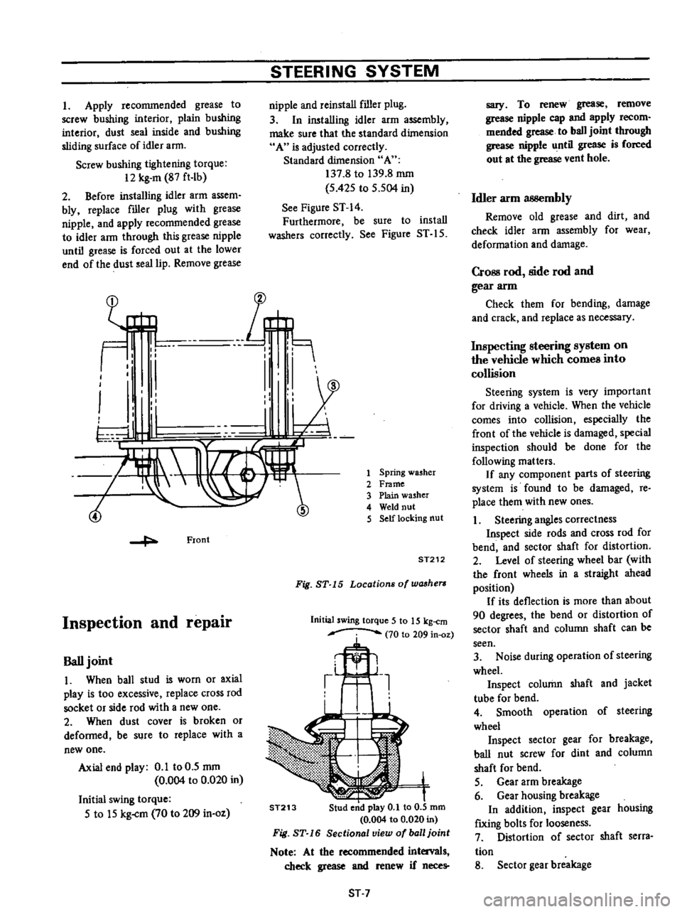
See
Figure
ST
14
Furthermore
be
sure
to
install
washers
correctly
See
Figure
ST
IS
Spring
washer
Frame
Plain
washer
Weld
nut
Self
locking
nut
ST212
Fig
ST
15
Locations
of
washers
Initial
swing
torque
5
to
15
kg
cm
70
to
209
in
oz
ST213
ST
7
sary
To
renew
grease
remove
grease
nipple
cap
and
apply
recom
mended
grease
to
ball
joint
through
grease
nipple
until
grease
is
forced
out
at
the
grease
vent
hole
Idler
arm
3B8embly
Remove
old
grease
and
dirt
and
check
idler
ann
assembly
for
wear
deformation
and
damage
CrOBS
rod
side
rod
and
gear
arm
Check
them
for
bending
damage
and
crack
and
replace
as
necessary
Inspecting
steering
system
on
the
vehicle
which
comes
into
collision
Steering
system
is
very
important
for
driving
a
vehicle
When
the
vehicle
comes
into
collision
especially
the
front
of
the
vehicle
is
damaged
special
inspection
should
be
done
for
the
following
matters
If
any
component
parts
of
steering
system
is
found
to
be
damaged
re
place
them
with
new
ones
1
Steering
angles
correctness
Inspect
side
rods
and
cross
rod
for
bend
and
sector
shaft
for
distortion
2
Level
of
steering
wheel
bar
with
the
front
wheels
in
a
straight
ahead
position
If
its
deflection
is
more
than
about
90
degrees
the
bend
or
distortion
of
sector
shaft
and
column
shaft
can
be
seen
3
Noise
during
operation
of
steering
wheel
Inspect
column
shaft
and
jacket
tube
for
bend
4
Smooth
operation
of
steering
wheel
Inspect
sector
gear
for
breakage
ball
nut
screw
for
dint
and
column
shaft
for
bend
S
Gear
arm
breakage
6
Gear
housing
breakage
In
addition
inspect
gear
housing
f
IXing
bolts
for
looseness
7
Distortion
of
sector
shaft
serra
tion
8
Sector
gear
breakage
Page 418 of 537
Engine
Control
Fuel
Exhaust
Systems
REMOVAL
AND
INSTALLATION
Accelerator
wire
I
Remove
air
cleaner
assembly
2
Disconnect
accelerator
wire
from
carburetor
3
Loosen
lock
nut
and
disconnect
accelerator
wire
outer
case
from
wire
holder
See
Figure
FE
I
4
Remove
spring
clamp
and
discon
nect
accelerator
wire
from
accelerator
pedal
arm
S
Remove
two
screws
securing
ac
celerator
wire
outer
case
to
body
and
detach
accelerator
wire
6
To
install
reverse
the
order
of
removal
Apply
recommended
multi
purpose
grease
slightly
to
portion
MG
shown
in
Figure
FE
I
Accelerator
pedal
assembly
I
Remove
spring
clamp
then
dis
connect
accelerator
wire
from
tip
of
pedal
ann
2
Remove
two
screws
securing
ac
celerator
pedal
bracket
to
body
3
Remove
accelerator
pedal
from
dash
panel
See
Figure
FE
I
4
To
install
reverse
the
order
of
removal
INSPECTION
I
Check
accelerator
pedal
return
spring
for
rust
fatigue
or
damage
Replace
if
necessary
2
Check
accelerator
wire
cases
and
fastening
locations
for
rust
damage
or
looseness
Repair
or
replace
if
necessary
ADJUSTMENT
Accelerstor
pedal
and
wire
Adjust
pedal
stopper
bolt
Section
A
so
as
to
obtain
specifi
ed
height
E
as
shown
in
Figure
FE
I
Secure
pedal
stopper
bolt
with
stopper
lock
nut
Refer
to
Figure
FE
I
E
78
mOl
3
07
in
Tightening
torque
01
nut
0
38
to
0
4S
kg
m
2
7
to
3
2
ft
b
2
Release
auto
choke
effect
since
throttle
lever
is
opened
by
fast
idle
earn
until
engine
warms
up
I
Keep
choke
valve
fully
open
with
fingers
2
Pull
throttle
lever
up
by
hand
1
Adjust
nut
2
Lock
nut
3
Accelerator
wire
4
Dust
co
r
5
After
completing
the
adjustment
as
previously
explained
check
the
following
I
Make
sure
that
accelerator
system
functions
smoothly
and
quietly
without
disturbing
any
adjacent
parts
2
Depress
accelerator
pedal
down
until
throttle
valve
fully
opens
Make
sure
that
the
clearance
T
between
accelerator
pedal
reverse
side
and
dash
floor
is
2
to
4
mm
0
08
to
0
16
in
without
floor
mat
Adjust
pedal
stop
per
bolt
and
lock
nut
if
beyond
limits
3
Check
throttle
lever
if
it
returns
to
the
original
position
as
soon
as
accelerator
pedal
is
released
FE
3
then
automatic
choke
effect
will
be
released
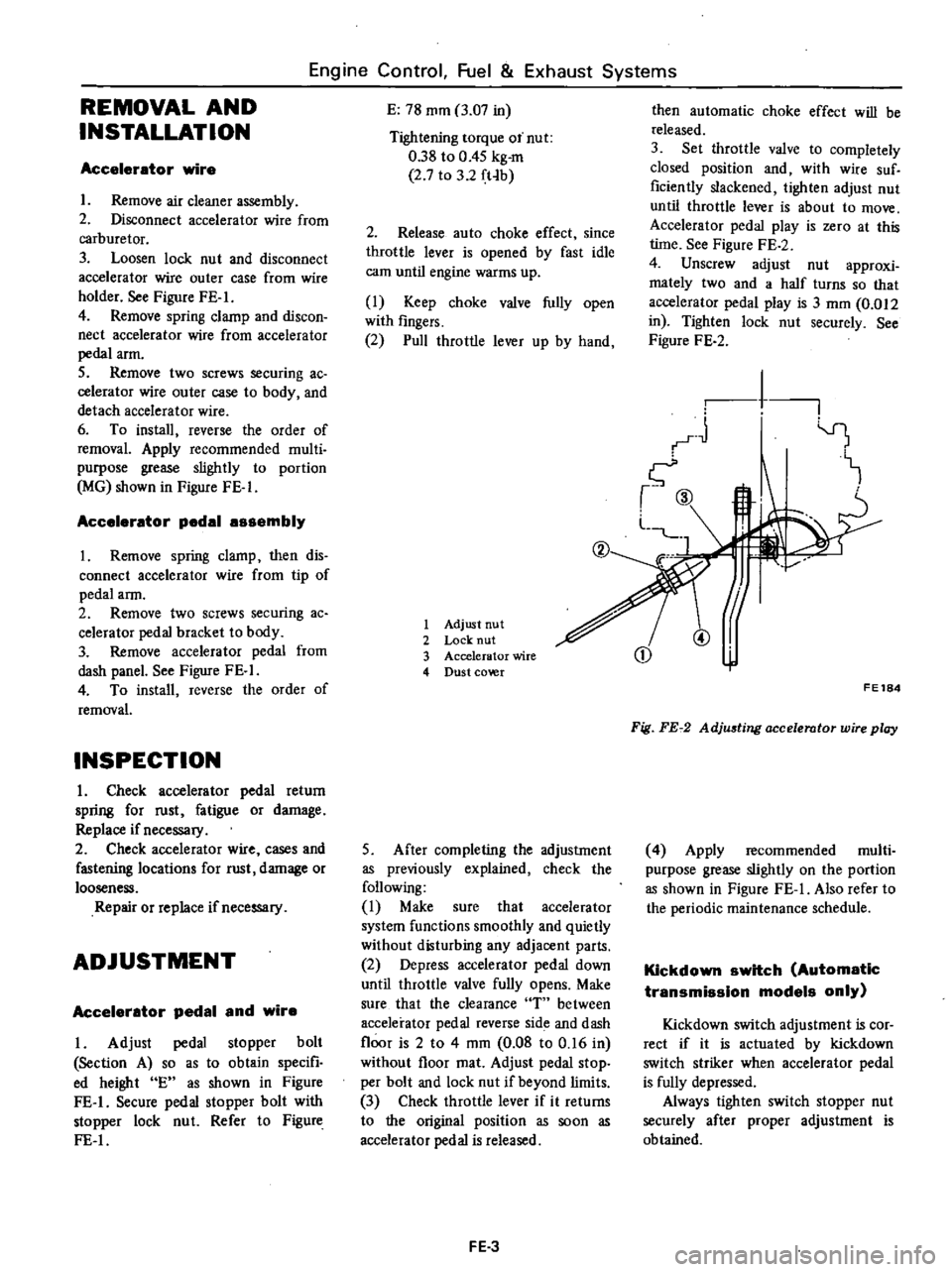
3
Set
throttle
valve
to
completely
closed
position
and
with
wire
suf
ficiently
slackened
lighten
adjust
nut
until
throttle
lever
is
about
to
move
Accelerator
pedal
play
is
zero
at
this
lime
See
Figure
FE
2
4
Unscrew
adjust
nut
approxi
mately
two
and
a
half
turns
so
that
accelerator
pedal
play
is
3
mOl
0
012
in
Tighten
lock
nut
securely
See
Figure
FE
2
1
I
1
CD
@
FE184
Fig
FE72
AdjU6ting
accelerator
wire
play
4
Apply
recommended
multi
purpose
grease
slightly
on
the
portion
as
shown
in
Figure
FE
I
Also
refer
to
the
periodic
maintenance
schedule
Kickdown
switch
Automatic
transmission
models
only
Kickdown
switch
adjustment
is
cor
rect
if
it
is
actuated
by
kickdown
switch
striker
when
accelerator
pedal
is
fully
depressed
Always
tighten
switch
stopper
nut
securely
after
proper
adjustment
is
obtained
Page 421 of 537
Engine
Control
Fuel
Exhaust
Systems
2
Remove
fuel
filter
INSPECTION
Fuel
tanle
Check
fuel
tank
for
cracks
or
deformation
If
necessary
replace
2
Fuel
hose
Inspect
all
hoses
for
cracks
fatigue
sweating
or
deterioration
Replace
any
hose
that
is
damaged
3
Fuel
tube
Replace
any
fuel
tube
that
is
crack
ed
rusted
collapsed
or
deformed
Note
Inspect
hoses
and
tubes
ac
cording
to
the
periodic
mainte
nance
schedule
4
Fuel
filter
Replace
fuel
filter
according
to
the
periodic
maintenance
schedule
or
when
it
is
clogged
or
restricted
DESCRIPTION
REMOVAL
DESCRIPTION
The
exhaust
systems
installed
on
the
non
California
models
differ
in
specifications
from
those
installed
on
the
California
models
Fuel
filter
is
of
a
cartridge
type
and
cannot
be
cleaned
Always
replace
with
a
new
one
5
Fuel
tank
gauge
unit
Check
gauge
unit
for
rust
deforma
tion
or
deterioration
If
necessary
replace
INSTALLATION
To
install
reverse
the
order
of
removal
Observe
the
following
I
Install
hose
clamps
securely
Do
not
tighten
excessively
to
avoid
damaging
hoses
2
Fasten
clips
holding
fuel
tube
on
under
body
securely
Failure
to
follow
this
caution
could
result
in
damage
to
the
surface
of
fuel
tube
3
Do
not
kink
or
twist
hose
and
tube
when
they
are
routed
EXHAUST
SYSTEM
CONTENTS
FE
6
FE
8
INSPECTION
INSTAllATION
Non
California
models
The
exhaust
system
consists
of
a
front
exhaust
tube
a
main
muffler
assembly
with
rear
tube
mounting
hangers
brackets
and
a
heat
insulator
FE
6
4
Install
fIller
hose
after
fuel
tank
has
been
mounted
in
place
Failure
to
follow
this
caution
could
result
in
leakage
from
around
hose
connections
5
When
installing
fuel
tank
gauge
unit
align
the
projection
of
tank
gauge
unit
with
the
notch
in
fuel
tank
and
tighten
it
securely
Be
sure
to
install
gauge
unit
with
O
ring
in
place
6
Run
engine
and
check
for
leaks
at
connections
Tightening
torque
Drain
plug
5
0
to
6
0
kg
m
36
to
43
ft
Ib
Fuel
tank
securing
bolt
0
8
to
1
I
kg
m
6
to
8
ft
Ib
Reservoir
tank
securing
bolt
032
to
0
44
kg
m
2
to
3
ft
Ib
FE
8
FE
8
California
models
The
exhaust
system
cOllsists
of
a
front
exhaust
tube
a
catalytic
conver
ter
assembly
a
center
tube
a
main
muffler
assembly
with
rear
tube
mounting
hangers
brackets
and
heat
insulators
The
catalytic
converter
is
COD
nected
to
the
front
tube
and
the
center
tube
with
bolts
and
nuts
Page 423 of 537

Engine
Control
Fuel
Exhaust
Systems
REMOVAL
Non
California
models
I
Remove
exhaust
tube
U
bolt
clamp
2
Break
sealant
off
at
front
tube
to
main
muffler
connectio
n
3
Remove
rear
tube
mounting
bolt
and
remove
muffler
assembly
with
rear
tube
4
Remove
front
tube
heat
insulator
5
Remove
nuts
securing
front
tube
to
exhaust
manifold
and
remove
front
tube
mounting
bolts
Then
detach
front
tube
When
disconnecting
the
exhaust
tube
connections
pay
attention
to
the
following
point
I
Break
old
se
lant
off
at
t
1e
connection
by
lightly
tapping
around
the
tube
witlJ
a
hammer
and
twisting
muffler
See
Figures
FE
7
and
FE
8
2
Using
a
rubber
hammer
tap
on
the
front
end
of
muffler
while
pushing
it
toward
rear
The
mumer
assembly
can
then
be
taken
out
See
Figure
FE
9
FE187
Fig
FE
7
Breaking
Bealant
FEl88
Fig
FE
8
Twisting
muffler
ijl
4
FE189
Fig
FE
9
Tapping
muffler
with
Q
rubber
hammer
California
models
I
Remove
all
heat
insulators
2
Remove
exhaust
tube
U
bolt
clamp
3
Break
sealant
off
at
center
tube
to
main
muffler
connection
4
Remove
rear
tube
mounting
bolt
and
remove
muffler
assembly
with
rear
tube
5
Remove
bolts
securing
catalytic
converter
to
center
tube
and
remove
center
tube
mounting
bolts
Then
detach
center
tube
6
Remove
bolts
and
nuts
securing
catalytic
converter
to
front
tube
and
detach
catalytic
converter
7
Remove
nuts
securing
front
tube
to
exhaust
manifold
and
remove
front
tube
mounting
bolts
Then
detach
front
tube
INSPECTION
I
Check
muffler
and
tubes
for
cracks
Qr
damage
Replace
any
part
that
is
damaged
beyond
limits
2
Replace
bracket
and
mounting
insulator
that
are
cracked
fatigued
or
sweated
FE
8
INSTALLATION
Install
the
exhaust
system
assembly
in
reverse
order
of
removal
Observe
the
following
Notes
a
Insert
front
tube
until
it
touches
emboss
b
When
there
is
110
clearance
between
front
tube
and
floor
or
propeUer
shaft
turn
tube
along
center
line
of
tube
in
the
manifold
connecting
unit
and
obtain
proper
clearance
c
Check
all
tube
connections
for
ex
haust
gas
leaks
and
entire
system
for
unusual
noises
with
engine
running
d
After
installation
check
that
mounting
brackets
and
mounting
rubbers
are
free
from
undue
stress
If
any
of
the
above
parts
is
not
installed
properly
excessive
noises
or
vibrations
may
be
transmitted
to
the
vehicle
body
e
Tightening
torque
Exhaust
manifold
to
front
tube
nut
1
9
to
2
5
kg
m
14
to
18
ft
lb
U
bolt
securing
nut
1
9
to
2
1
kg
m
14
to
15
ft
lb
Mounting
bracket
bolt
1
0
to
1
2
kg
m
710
9
ft
lb
Front
tube
mounting
bracket
bolt
california
models
1
9
to
2
1
kg
m
14
to
15
ft
lb
Catalytic
converter
to
front
and
center
tube
bolt
California
models
3
2
to
4
3
kg
m
23
to
31
ft
Ib
If
exhaust
tubes
are
separated
at
connection
t
renew
muffler
assembly
etc
use
the
Genuine
Nissan
Sealant
Exhaust
Sealant
Kit
20720
N2225
or
equivalent
See
Figure
FE
IO
to
eliminate
gas
leakage
at
the
joint
Be
sure
to
observe
the
following
Page 424 of 537

Engine
Control
Fuel
Exhaust
Systems
I
Wipe
clean
all
the
contact
por
tions
of
tube
joints
allow
them
to
dry
thoroughly
2
Temporarily
mount
in
place
muffler
assembly
as
an
assembled
unit
on
the
vehicle
3
Insert
front
tube
until
it
touches
emboss
m
b
nlfrnnjj
mm
lJ
Ij
@L
J
FE263
Fig
FE
ll
Exhawt
tube
connection
4
Torque
nut
securing
the
male
and
female
tubes
at
the
connection
Tightening
torque
is
1
6
to
2
0
kg
m
12
to
14
ft
lb
5
Squeeze
approximately
5
CC
0
31
cu
in
of
sealant
into
injection
from
sealant
tube
See
Figure
FE
12
Sealant
tube
polyethylene
Injector
Fig
FE
IO
Exhaust
sealant
kit
Be
sure
to
place
cap
back
to
sealant
tube
since
sealant
will
dry
Approximately
5
cc
0
31
Cll
in
FE1l1
Fig
FE
12
Squeezing
sealant
to
injec
tor
6
Position
nozzle
of
injector
to
the
guide
and
press
it
there
firmly
Inject
sealant
slowly
until
sealant
begins
to
flow
out
of
the
slit
of
tube
This
indicates
that
the
bead
requires
no
further
sealant
Excessive
sealant
can
cause
a
clogged
tube
See
Figure
FE
13
After
injecting
wash
injector
thoroughly
in
clean
water
to
remove
all
traces
of
sealant
FE191
Fig
FE
13
Injecting
sealant
FE
9
7
Start
engine
and
let
it
idle
slowly
for
ten
minutes
minimum
to
hilfden
sealant
with
the
heat
of
exhaust
gas
8
Check
the
condition
of
sealant
before
driving
the
vehicle
It
is
also
essential
that
the
vehicle
should
not
be
accelerated
sharply
for
20
to
30
minutes
subsequent
to
this
operation
Noles
a
The
sealant
should
be
used
within
guaranty
term
indicated
on
the
kit
case
b
Exposure
of
sealant
to
the
skin
may
cause
a
rash
Wash
sealant
off
the
skin
with
water
c
Do
not
keep
the
sealant
tube
in
a
place
where
the
ambient
tempera
ture
is
above
400C
I040F
A
sealant
hardened
above
4QoC
I040F
cannot
be
used
The
most
suitable
storage
temperature
is
from
15
to
350C
59
to
950F
If
sealant
becomes
hardened
because
of
low
temperatures
wann
the
sealant
tube
with
lukewarm
water
until
the
sealant
is
softened
Do
not
warm
tube
at
a
temperature
over
400C
1040F
for
a
long
time
d
Thoroughly
read
the
instruction
sheet
furnished
with
the
kit
before
using
the
sealant
i
Page 431 of 537
Body
Frame
BODY
FRONT
END
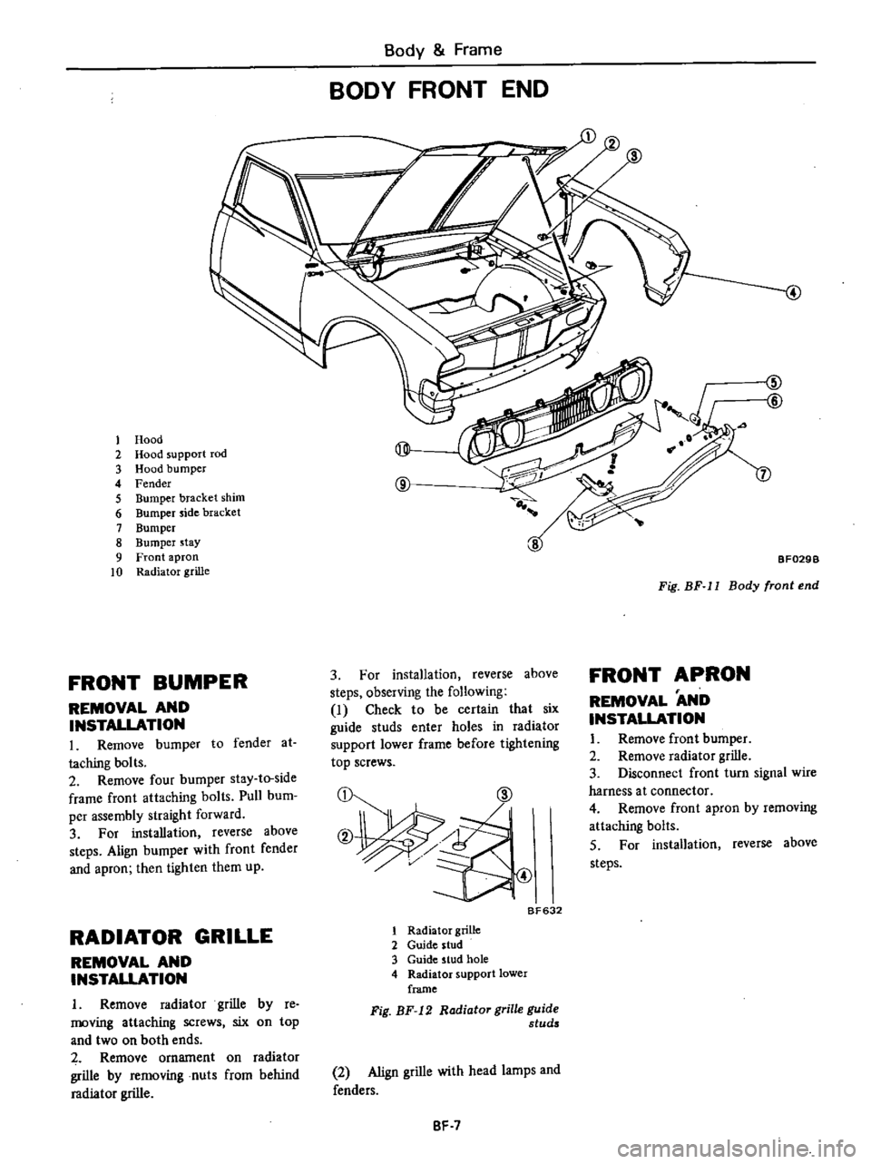
1
Hood
2
Hood
support
rod
@
3
Hood
bumper
4
Fender
@
5
Bumper
bracket
shim
6
Bumper
side
bracket
7
Bumper
8
Bumper
stay
9
Front
apron
10
Radiator
grille
FRONT
BUMPER
REMOVAL
AND
INSTALLATION
L
Remove
bumper
to
fender
at
taching
bolts
2
Remove
four
bumper
stay
to
side
frame
front
attaching
bolts
Pull
bum
per
assembly
straight
forward
3
For
installation
reverse
above
steps
Align
bumper
with
front
fender
and
apron
then
tighten
them
up
RADIATOR
GRILLE
REMOVAL
AND
INSTAUATION
I
Remove
radiator
grille
by
re
moving
attaching
screws
six
on
top
and
two
on
both
ends
Remove
ornament
on
radiator
grille
by
removing
nuts
from
behind
radiator
grille
4
ZID
@
7
BF029B
Fig
BF
11
Body
front
end
FRONT
APRON
3
For
installation
reverse
above
steps
observing
the
following
I
Check
to
be
certain
that
six
guide
studs
enter
holes
in
radiator
support
lower
frame
before
tightening
top
screws
CD
@
REMOVAL
AND
INSTALLATION
I
Remove
front
bumper
2
Remove
radiator
grille
3
Disconnect
front
turn
signal
wire
harness
a
t
connector
4
Remove
front
apron
by
removing
attaching
bolts
S
For
installation
reverse
above
steps
B
632
1
Radiator
grille
2
Guide
stud
3
Guide
stud
hole
4
Radiator
support
lower
frame
Fig
BF
12
Radiator
grille
guide
studs
2
Align
grille
with
head
lamps
and
fenders
BF
7
Page 434 of 537
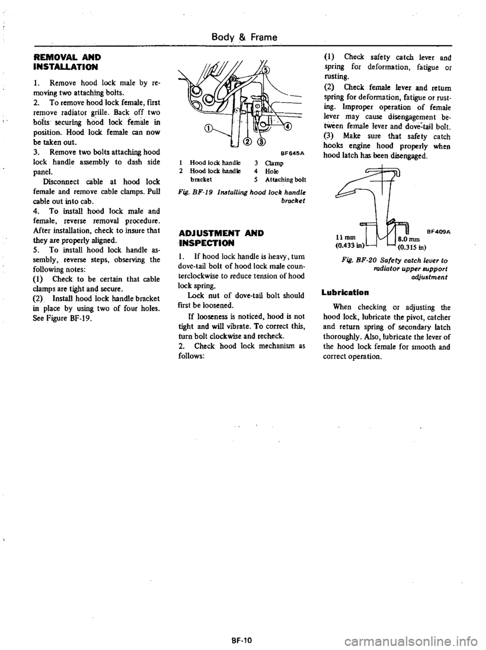
REMOVAL
AND
INSTALLATION
I
Remove
hood
lock
male
by
re
moving
two
attaching
bolts
2
To
remove
hood
lock
female
first
remove
radiator
grille
Back
off
two
bolts
securing
hood
lock
female
in
position
Hood
lock
female
can
now
be
taken
out
3
Remove
two
bolts
attaching
hood
lock
handle
assembly
to
dash
side
paneL
Disconnect
cable
at
hood
lock
female
and
remove
cable
clamps
Pull
cable
out
into
cab
4
To
install
hood
lock
male
and
female
reverse
removal
procedure
Mter
installation
check
to
insure
that
they
are
properly
aligned
5
To
install
hood
lock
handle
as
sembly
reverse
steps
observing
the
following
notes
I
Check
to
be
certain
that
cable
clamps
are
tight
and
secure
2
Install
hood
lock
handle
bracket
in
place
by
using
two
of
four
holes
See
Figure
BF
19
Body
Frame
@
1
Hood
tock
handle
2
Hood
lock
handle
bracket
BF645A
3
Clamp
4
Hole
5
Attaching
bolt
Fig
BF
19
1MtalIing
hood
lock
handle
brocket
ADJUSTMENT
AND
INSPECTION
I
If
hood
lock
handle
is
heavy
turn
dove
tail
bolt
of
hood
lock
male
coun
terclockwise
to
reduce
tension
of
hood
lock
spring
Lock
nut
of
dove
tail
bolt
should
fust
be
loosened
If
looseness
is
noticed
hood
is
not
tight
and
will
vibrate
To
correct
this
turn
bolt
clockwise
and
recheck
2
Check
hood
lock
mechanism
as
follows
BF
10
I
Check
safety
catch
lever
and
spring
for
deformation
fatigue
or
rusting
2
Check
female
lever
and
return
spring
for
deformation
fatigue
or
rust
ing
Improper
operation
of
female
lever
may
cause
disengagement
be
tween
female
lever
and
dove
tail
bolt
3
Make
sure
that
safety
catch
hooks
engine
hood
properly
when
hood
latch
has
been
disengaged
0l
11
mm
I
nun
BF409A
0
433
in
0
3t5
in
Fig
BF
20
Safety
catch
lever
to
radiator
upper
support
acVu5tment
Lubrication
When
checking
or
adjusting
the
hood
lock
lubricate
the
pivot
catcher
and
return
spring
of
secondary
latch
thoroughly
Also
lubricate
the
lever
of
the
hood
lock
female
for
smooth
and
correct
operation
Page 436 of 537

@
I
r
L
c
@
DESCRIPTION
The
door
consists
of
inner
and
outer
panels
welded
together
to
form
a
rigid
structure
The
curved
glass
provides
greater
shoulder
room
A
door
that
incorporates
a
ventila
tor
window
is
also
available
as
an
option
The
weatherstrip
is
inserted
into
the
groove
on
the
door
sash
side
and
is
attached
by
clips
on
the
door
side
DOOR
REMOVAL
AND
INSTALLATION
I
With
door
in
full
open
position
place
a
garage
jack
or
stand
beneath
door
to
support
its
weight
when
bolts
are
removed
Place
rag
between
door
and
jack
or
stand
to
avoid
damaging
painted
surface
Body
Frame
CD
1
@
@
ID
@
AJ
@
@
@
1
Door
sash
2
Window
outside
weatherstrip
3
Window
inside
weatherstrip
4
Door
atherstrip
5
Rear
glass
run
rubber
6
Door
finish
holder
7
Rear
lower
sash
8
Seal
screen
9
Door
weatherstrip
clip
10
Front
glass
run
rubber
11
Lower
door
hinge
12
Upper
door
hinge
13
Front
lower
sash
14
Door
glass
15
Glazing
rubber
16
Door
glass
bottom
channel
11
Lower
support
18
Upper
support
19
Door
ventilator
assembly
BF031B
Fig
BF
22
Door
with
ntilator
window
Optional
BF023
Fig
BF
23
Supporting
door
2
Separate
lower
door
hinge
hole
cover
from
dash
side
trim
3
While
supporting
door
as
above
back
off
body
to
upper
and
lower
hinge
attaching
bolts
accessible
from
inside
cab
three
each
Door
can
now
be
taken
out
from
cab
body
I
t
I
l
f
p1
1
W
JJ
i
Sl
j
Fig
BF
24
Removing
door
hinge
bolt
8F
12
4
To
install
reverse
removal
pro
cedure
ALIGNMENT
Elongated
holes
three
each
in
door
hinge
and
door
lock
striker
pro
vide
for
up
and
down
forward
and
backward
and
or
sideways
adjustment
to
assure
proper
door
fit
to
door
opening
To
adjust
door
alignment
loosen
bolts
and
move
door
to
desired
posi
lion
to
obtain
a
parallel
space
between
door
sides
and
door
opening
Also
check
to
be
certain
that
weatherstrip
contacts
body
opening
evenly
to
pre
vent
entry
of
mud
and
water
DOOR
TRIM
AND
SEAL
REMOVAL
AND
INSTALLATION
1
Remove
screw
securing
inside
door
handle
escutcheon
remove
es
cutcheon
2
Remove
screws
which
hold
pull
handle
and
arm
rest
in
position
Pull
handle
and
arm
rest
can
then
be
taken
out
3
Pull
retaining
spring
off
regulator
handle
Take
out
regulator
handle
and
seat
washer
Page 440 of 537
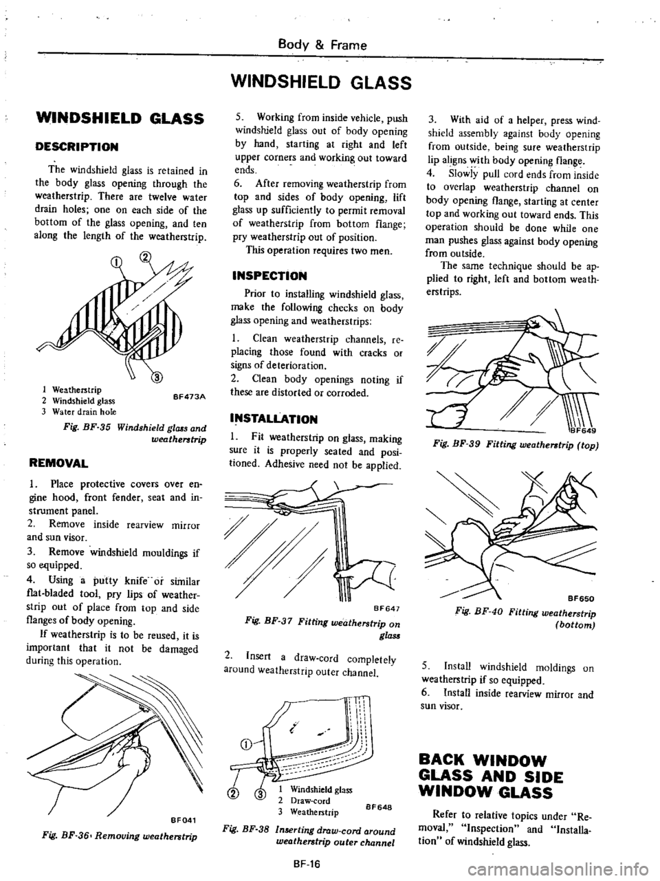
WINDSHIELD
GLASS
DESCRIPTION
The
windshield
glass
is
retained
in
the
body
glass
opening
through
the
weatherstrip
There
are
twelve
water
drain
holes
one
on
each
side
of
the
bottom
of
the
glass
opening
and
ten
along
the
length
of
the
weatherstrip
1
Weatherstrip
2
Windshield
glass
3
Water
drain
hole
Fig
BF
35
Windshield
glass
and
weatherstrip
BF473A
REMOVAL
1
Place
protective
covers
over
en
gine
hood
front
fender
seat
and
in
strument
panel
2
Remove
inside
rearview
mirror
and
sun
visor
3
Remove
windshield
mouldings
if
so
equipped
4
Using
a
putty
knife
or
similar
flat
bladed
tool
pry
lips
of
weather
strip
out
of
place
from
top
and
side
flanges
of
body
opening
If
weatherstrip
is
to
be
reused
it
is
important
that
it
not
be
damaged
during
this
operation
BF041
Fig
BF
36
Removing
weatherstrip
Body
Frame
WINDSHIELD
GLASS
5
Working
from
inside
vehicle
push
windshield
glass
out
of
body
opening
by
hand
starting
at
right
and
left
upper
COIners
and
working
out
toward
ends
6
After
removing
weatherstrip
from
top
and
sides
of
body
opening
lift
glass
up
sufficiently
to
permit
removal
of
weatherstrip
from
bottom
flange
pry
weatherstrip
out
of
position
This
operation
requires
two
men
INSPECTION
Prior
to
installing
windshield
glass
make
the
following
checks
on
body
glass
opening
and
weatherstrips
I
Clean
weatherstrip
channels
re
placing
those
found
with
cracks
or
signs
of
deterioration
2
Clean
body
openings
noting
if
these
are
distorted
or
corroded
INSTALLATION
L
Fit
weatherstrip
on
glass
making
sure
it
is
properly
seated
and
posi
tioned
Adhesive
need
not
be
applied
0
BF641
Fig
BF
37
Fitting
weatherstrip
on
glass
2
Insert
a
draw
cord
completely
around
weatherstrip
outer
channel
Q
i
I
dYii
1
Windshield
glass
2
Draw
cord
3
Weatherstrip
Fig
BF
38
In8erting
draw
cord
around
weatherstrip
outer
channel
8F648
BF
16
3
With
aid
of
a
helper
press
wind
shield
assembly
against
body
opening
from
outside
being
sure
weatherstrip
lip
aligns
ith
body
opening
flange
4
Slowly
pull
cord
ends
from
inside
to
overlap
weatherstrip
channel
on
body
opening
flange
starting
at
center
top
and
working
out
toward
ends
This
operation
should
be
done
while
one
man
pushes
glass
against
body
opening
from
outside
The
same
technique
should
be
ap
plied
to
right
left
and
bottom
wea
th
erstrips
Fig
BF
39
Fitting
weatherstrip
top
BF650
Fig
BF
40
Fitting
weatherstrip
bottom
5
Install
windshield
moldings
on
weatherstrip
if
so
equipped
6
Install
inside
rearview
mirror
and
sun
visor
BACK
WINDOW
GLASS
AND
SIDE
WINDOW
GLASS
Refer
to
relative
topics
under
Re
moval
Inspection
and
Installa
tion
of
windshield
glass
Page 445 of 537

Body
Frame
Note
When
installing
emergency
locking
retractor
make
sure
that
it
is
set
vertically
@
I
g@
BF650A
Fig
BF
51
Seat
belt
anchorages
8F
21
INSPECTION
OF
BUCKLE
SWITCH
The
contacts
of
the
buckle
switch
are
normally
closed
When
tongue
latches
the
buckle
tip
end
of
the
tongue
pushes
the
push
rod
to
open
the
switch
contacts
I
Disconnect
battery
ground
cable
2
Disconnect
buckle
switch
wire
harness
3
Using
a
test
light
check
buckle
switch
for
proper
operation
The
light
should
go
out
when
tongue
of
outer
lap
belt
latches
buckle
and
go
on
when
it
unlatches
buckle
Replace
belt
assembly
if
necessary
Note
When
checking
buckle
switch
operation
make
sure
that
power
is
held
below
16
volts
and
13
mA