lock DATSUN PICK-UP 1977 Workshop Manual
[x] Cancel search | Manufacturer: DATSUN, Model Year: 1977, Model line: PICK-UP, Model: DATSUN PICK-UP 1977Pages: 537, PDF Size: 35.48 MB
Page 181 of 537
Engine
Electrical
System
B
v
W
WR
WL
L2
VOLTAGE
REGULATOR
co
LW
I
P
B
r
FUSIBLE
LINK
m
I
WLI
LW
cJ
I
B
t
EARTH
POINT
m
WR
WR
CHARGE
g
00
WARNING
lAMP
00000
Equipped
with
cooler
I
I
I
I
TjT
m
CLB
W
WB
B
YWR
I
I
I
I
1
W
B
rn
ALTERNATOR
I
l
LW
BW
j
J
M
IG
I
W
BwtIl
IGNITION
SWITCH
COLOR
CODE
B
Black
OW
Black
with
white
stripe
W
White
WB
White
with
black
stripe
WR
White
with
red
stripe
WL
White
with
blue
stripe
LO
Blue
with
black
stripe
LW
Blue
with
white
stripe
Y
Yellow
lOA
C
o
0
0
0
o
0
0
FUSE
BLOCK
M
0
0
0
lOA
Ii
California
models
E
E492
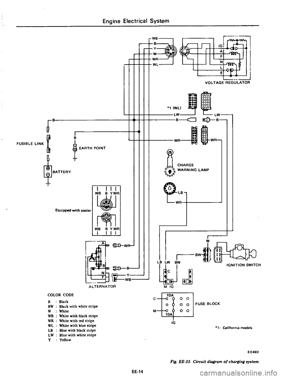
Fig
EE
25
Circuit
diagram
of
charging
lfY
t
m
EE
14
Page 187 of 537

DESCRIPTION
MEASUREMENT
OF
REGULATOR
VOLTAGE
ADJUSTMENT
VOLTAGE
REGULATOR
DESCRIPTION
The
regulator
consists
basically
of
a
voltage
regulator
and
a
charge
relay
The
voltage
regulator
has
two
sets
of
contact
points
a
lower
set
and
an
upper
set
to
control
alternator
volt
age
An
armature
plate
placed
between
the
two
sets
of
contacts
moves
upward
or
downward
or
vibrates
The
lower
contacts
when
closed
complete
the
jCV
ID@
@
GJ
I
@
@
@
Engine
Electrical
System
REGULATOR
CONTENTS
EE
20
CHARGING
RELAY
SERVICE
DATA
AND
SPECIFICATIONS
TROUBLE
DIAGNOSES
AND
CORRECTIONS
Including
alternatorl
EE
25
EE
23
EE
24
EE
20
EE
23
EE
23
field
circuit
direct
to
ground
and
the
upper
contacts
when
closed
complete
the
field
circuit
to
ground
through
a
resistance
field
coil
and
produce
alternator
output
The
charge
relay
i
similar
in
construction
to
the
voltage
regulator
When
the
upper
contacts
are
closed
charge
warning
lamp
goes
on
v
1
Charge
relay
2
Voltage
regulator
EE285
Fig
EE
46
View
of
removing
cover
As
regards
the
construction
the
voltage
regulator
is
very
similar
to
the
charge
relay
as
shown
in
Figure
EE47
@
r
J
CD
@
@
@
Q
@
ID@
ID@
J
t
L
T
@
r
b
r
CD
L
@
j
1
g
f
@
@
EEJ97
J
I1Jlccting
spring
2
Y
kt
g
p
3
Armaturc
4
Core
go
5
Low
Sllccd
lnlacl
h
Point
ap
7
High
speed
conlat
t
8
Contact
c
9
3111111
0
118
ill
di
10
41l1I11W
157in
c1ia
few
II
Cuil
12
lock
nut
J3
Adjllslin
screw
14
Adjll
sting
sprin
15
Yoke
9
Adjusting
screw
10
Lock
nut
11
Coil
12
4mm
0
157
in
dia
screw
13
3mm
0
118
in
dla
crew
14
Contact
iet
15
Voltage
cgulatm
contact
a
Cnl1
Tlll
tion
f
lltagl
l
j
llIOltllT
I
Point
gilp
2
Charge
relay
contllct
3
Core
gap
4
ArlllatlJre
5
Connecting
sprin
6
Yoke
gap
7
Yoh
B
Adjusting
pring
b
Construction
of
charge
relay
Fig
EE
47
Structural
vi
w
EE
20
Page 190 of 537
ADJUSTMENT
VOLTAGE
REGULATOR
When
regulating
voltage
as
meas
ured
above
deviates
from
rated
value
adjust
regulator
in
accordance
with
the
following
instructions
I
Inspect
contact
surface
and
if
rough
lightly
polish
with
fine
emery
paper
1
500
or
600
2
Measure
each
gap
and
adjust
if
necessary
Adjust
core
gap
and
point
gap
in
that
order
No
adjustment
is
required
for
yoke
gap
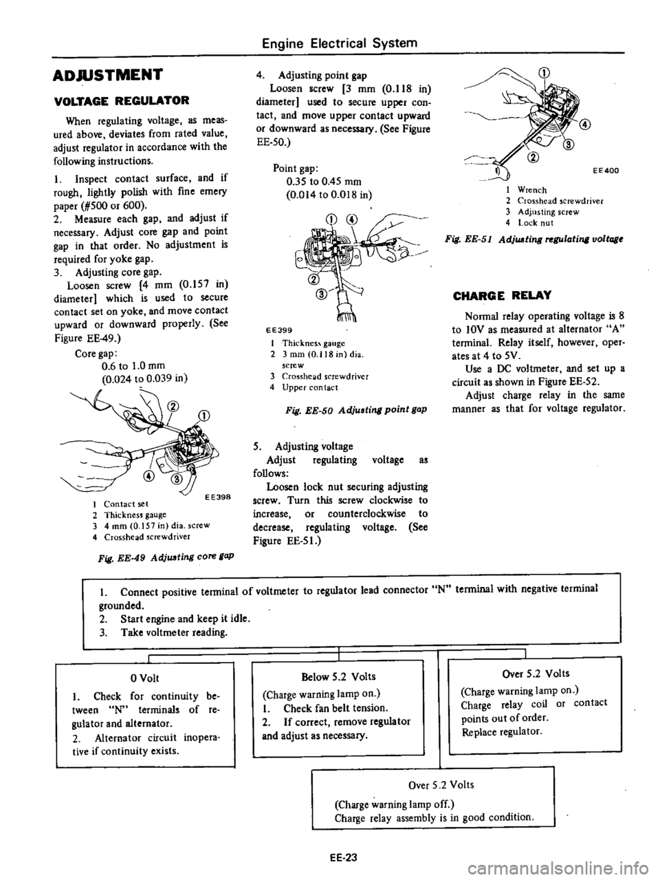
3
Adjusting
core
gap
Loosen
screw
4
mm
0
157
in
diameter
which
is
used
to
secure
contact
set
on
yoke
and
move
contact
upward
or
downward
properly
See
Figure
EE
49
Core
gap
0
6
to
1
0
mm
0
024
to
0
039
in
EE398
I
Contact
set
2
ThicknesJ
gauge
3
4
mm
0
157
in
dia
screw
4
Crosshead
Jcrewdriver
Fig
EE
49
AdjUJJting
core
gap
Engine
Electrical
System
4
Adjusting
point
gap
Loosen
screw
3
mm
O
lIS
in
diameter
used
to
secure
upper
con
tact
and
move
upper
contact
upward
or
downward
as
necessary
See
Figure
EE
50
Point
gap
035
to
0
45
mm
0
014
to
O
D1S
in
EE399
I
Thicknes
gauge
2
3
mm
0
118
in
dia
screw
3
Cro
Sshelld
screwdriver
4
Upper
contact
Fig
EE
50
Adjusting
point
gap
5
Adjusting
voltage
Adjust
regulating
voltage
as
follows
Loosen
lock
nut
securing
adjusting
screw
Turn
this
screw
clockwise
to
increase
or
counterclockwise
to
decrease
regulating
voltage
See
Figure
EE
5
J
CD
EE400
I
Wrench
2
Crosshead
screwdriver
3
Adjusting
screw
4
l
ock
nut
Fig
EE
51
AdjUJJting
rel
Ulating
voltage
CHARGE
RELAY
Nonna
relay
operating
voltage
is
S
to
IOV
as
measured
at
alternator
A
tenninal
Relay
itself
however
oper
ates
at
4
to
5V
Use
a
DC
voltmeter
and
set
up
a
circuit
as
shown
in
Figure
EE
52
Adjust
charge
relay
in
the
same
manner
as
that
for
voltage
regulator
L
Connect
positive
tenninal
of
voltmeter
to
regulator
lead
connector
N
tenninal
with
negative
terminal
grounded
2
Start
engine
and
keep
it
idle
3
Take
voltmeter
reading
o
Volt
I
Check
for
continuity
be
tween
terminals
of
re
gulator
and
alternator
2
Alternator
circuit
inopera
tive
if
continuity
exists
Below
5
2
Volts
Charge
warning
lamp
on
I
Check
fan
belt
tension
2
If
correct
remove
regulator
and
adjust
as
necessary
Over
5
2
Volts
Charge
warning
lamp
on
Charge
relay
coil
or
contact
points
out
of
order
Replace
regulator
Over
5
2
Volts
Charge
warning
lamp
off
Charge
relay
assembly
is
in
good
condition
EE
23
Page 196 of 537
EARTH
POINT
r
W
b
FUSIBLE
LINK
BATTERY
L
d
l
ilR
j
i
BW
@
c
RESISTOR
COLOR
CODE
8
Black
OW
Black
with
white
stripe
DR
Black
with
red
stripe
W
White
L
Blue
R
Red
G
Green
Engine
Electrical
System
TRANSISTOR
IGNITION
UNIT
IHIIl
II
II
BW
BBV
RG
111
I
I
TERMINAL
BLOCK
r
c
IGNITION
COIL
BW
B
ml
BR
lliJ
LldJ0
IGNITION
SWITCH
EE
29
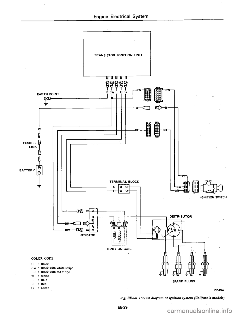
Fig
EE
56
Circuit
diagram
of
ignition
system
California
models
EE494
a
B
lof1
@
00
00
00
SR
00
00
Et
liiI
in
D1STRliUTOR
10
0
i9
J
SPARK
PLUGS
Page 200 of 537
Engine
Electrical
System
SERVICE
DATA
AND
SPECIFICATIONS
D4A4
06
D4A4
07
Type
D4A6
07
D4A6
08
Firing
order
1
3
4
2
13
4
2
Rotating
direction
Counterclockwise
Counterclockwise
Owen
angle
degree
490
to
550
490
to
550
Point
gap
mm
in
0
45
to
0
55
0
45
to
0
55
0
018
to
0
022
0
018
to
0
022
Point
pressure
kg
lb
0
40
to
0
55
0
40
to
0
55
0
88
to
1
21
0
88
to
1
21
Condenser
capacity
JlF
0
20
to
0
24
0
20
to
0
24
Condenser
isolate
resistance
Mrl
5
5
Cap
isolate
resistance
Mrl
50
50
Rotor
head
isolate
resistance
Mrl
50
50
Cap
carbon
point
length
mm
in
10
0
39
10
0
39
For
Canada
DISTRIBUTOR
California
models
CONSTRUCTION
CHECKING
AND
ADJUSTMENT
CAP
AND
ROTOR
HEAD
AIR
GAP
CONSTRUCTION
In
the
conventional
distributor
the
ignition
liming
is
detected
by
the
cam
and
breaker
arm
while
in
this
transis
tor
ignition
unit
it
is
detected
by
the
reluctor
on
the
shaft
and
the
pick
up
coil
provided
in
place
of
the
breaker
The
pick
up
coil
consists
of
a
magnet
coil
etc
The
amount
of
magnetic
flux
passing
through
the
pole
piece
in
the
coil
is
changed
at
the
moment
the
pole
CONTENTS
EE
33
EE
33
EE
33
EE
33
ADVANCE
MECHANISMS
DISASSEMBLY
ASSEMBLY
SERVICE
DATA
AND
SPECIFICATIONS
EE
33
EE
35
EE
35
EE
36
piece
faces
the
protrusion
of
the
re
luctor
and
then
the
electrical
signal
is
genera
ted
in
the
pick
up
coil
This
electric
signal
is
conducted
into
the
transistor
ignition
unit
which
in
turn
breaks
tI
e
primary
coil
current
running
through
the
ignition
coil
and
generates
high
voltage
in
the
secondary
winding
Also
this
transistor
ignition
EE
33
unit
utilizes
this
electric
signal
to
restore
the
primary
coil
to
the
original
state
after
cutting
off
the
primary
current
for
a
fIXed
time
The
centrifugal
and
vacuum
ad
vance
mechanisms
employ
the
con
ventional
mechanical
type
The
con
tactor
is
used
to
eliminate
vacuum
and
centrifugal
advance
hysteresis
I
Page 201 of 537

t3
l
l
J
@
r
9
V
fW
@
@
CHECKING
AND
ADJUSTMENT
CAP
AND
ROTOR
HEAD
Cap
and
rotor
head
must
be
in
spected
periodically
as
specified
in
the
Maintenance
Schedule
Remove
cap
and
clean
all
dust
and
carbon
deposits
from
cap
and
rotor
from
time
to
time
If
cap
is
cracked
or
is
leaking
replace
with
a
new
one
AIR
GAP
Standard
air
gap
is
0
2
to
0
4
mm
0
008
to
0
016
in
If
the
gap
is
off
the
standard
adjustment
mould
be
made
by
loos
ening
pick
up
coil
screws
Gap
gauge
is
required
for
adjust
ment
Air
gaps
must
be
checked
from
time
to
time
Air
gap
0
2
to
0
4
mm
0
008
to
0
016
in
Engine
Electrical
System
tl
@
9
EE328
Fig
EE
67
Checking
oir
gap
To
remove
pick
up
cail
disconnect
distributor
harness
at
terminal
block
and
remove
screw
securing
pick
up
coil
ADVANCE
MECHANISMS
Specifications
Type
Item
Vacuum
advance
Distributor
degrees
Distributor
mmHg
inHg
Centrifugal
advance
Distributor
degrees
Distributor
cpm
EE34
1
Cap
assembly
2
Rotor
head
a55embly
3
Roll
pin
4
ReJuctor
S
Pick
up
coil
6
Contactoi
7
Breaker
plate
assembly
8
Packing
9
Rotor
shaft
10
Governor
spring
11
Governor
weigh
t
12
Shaft
a
Jscmbly
13
Cap
setter
14
Vacuum
controller
15
Housing
16
Fixing
plate
17
O
ring
18
Collar
EE327
Fig
EE
66
Exploded
view
of
di3tributor
assembly
and
distributor
harness
to
their
positions
EE329
Fig
EE
68
Remouing
pick
up
coil
D4F4
04
D4F4
Q3
Manual
Automatic
00
150
5
91
30
250
9
84
00
550
110
2
300
00
600
110
1
950
Page 203 of 537
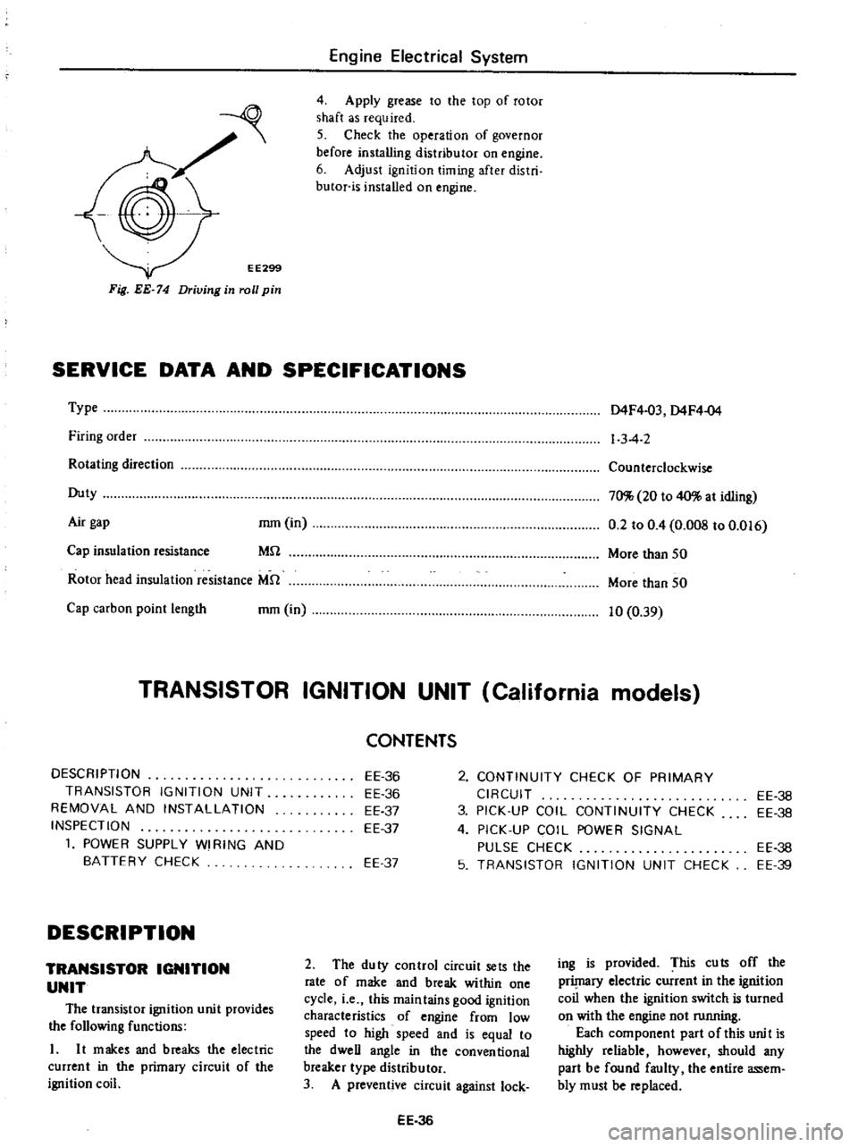
EE299
Fig
EE
74
Driving
in
roll
pin
Engine
Electrical
System
4
Apply
grease
to
the
top
of
rotor
shaft
as
required
5
Check
the
operation
of
governor
before
installing
distributor
on
engine
6
Adjust
ignition
timing
after
distri
butor
is
installed
on
engine
SERVICE
DATA
AND
SPECIFICATIONS
Type
Firing
order
Rotating
direction
Duty
Air
gap
mm
in
MU
Cap
insulation
resistance
Rotor
head
insulation
resistance
MU
Cap
carbon
point
length
mm
in
D4F4
03
D4F4
04
1
3
4
2
Counterclockwise
70
20
to
40
at
idling
0
2
to
0
4
O
OOS
to
0
016
More
than
50
More
than
50
10
0
39
TRANSISTOR
IGNITION
UNIT
California
models
DESCRIPTION
TRANSISTOR
IGNITION
UNIT
REMOVAL
AND
INSTALLATION
INSPECTION
1
POWER
SUPPLY
WI
RING
AND
BATTERY
CHECK
DESCRIPTION
TRANSISTOR
IGNITION
UNIT
The
transistor
ignition
unit
provides
the
following
functions
L
It
makes
and
breaks
the
electric
current
in
the
primacy
circuit
of
the
ignition
coil
2
CONTINUITY
CHECK
OF
PRIMARY
CIRCUIT
3
PICK
UP
COIL
CONTINUITY
CHECK
4
PICK
UP
COIL
POWER
SIGNAL
PULSE
CHECK
5
TRANSISTOR
IGNITION
UNIT
CHECK
CONTENTS
EE
36
EE
36
EE
37
EE
37
EE
37
2
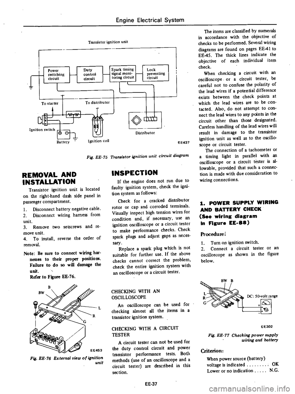
The
duty
control
circuit
sets
the
rate
of
make
and
break
within
one
cycle
i
e
this
maintains
good
ignition
characteristics
of
engine
from
low
speed
to
high
speed
and
is
equal
to
the
dweU
angle
in
the
conventional
breaker
type
distributor
3
A
preventive
circuit
against
lock
EE
36
EE
36
EE
38
EE
38
EE
39
ing
is
provided
This
cuts
off
the
prilnaCY
electric
current
in
the
ignition
coil
when
the
ignition
switch
is
turned
on
with
the
engine
not
running
Each
component
part
of
this
unit
is
highly
reliable
however
should
any
part
be
found
faulty
the
entire
assem
bly
must
be
replaced
Page 204 of 537
Engine
Electrical
System
Transistor
ignition
unit
r
1
Power
switching
circuit
Duty
control
circuit
To
starter
To
distributor
Ba
ttery
Ignition
coil
1
Spark
timing
1
Signal
mom
toring
circuit
Lock
j
preven
ling
circuit
nm
Distributor
EE437
Fig
EE
75
Transistor
ignition
unit
circuit
diagram
REMOVAL
AND
INSTALLATION
Transistor
ignition
unit
is
located
on
the
right
hand
dash
side
panel
in
passenger
compartment
Disconnect
battery
negative
cable
2
Disconnect
wiring
harness
from
unit
3
Remove
two
setscrews
and
te
move
unit
4
To
install
reverse
the
order
of
removal
Note
Be
sure
to
connect
wiring
har
nesses
to
their
proper
positio
Failure
to
do
so
will
damage
the
unit
Refer
to
Figure
EE
76
Fig
EE
76
External
view
of
ignition
unit
INSPECTION
If
the
engine
does
not
run
due
to
faulty
ignition
system
check
the
igni
tion
system
as
follows
Check
for
a
cracked
distributor
rotor
or
cap
and
corroded
tenninals
Visually
inspect
high
tension
wires
for
condition
and
if
necessary
use
an
ignition
oscilloscope
or
a
circuit
tester
to
make
performance
checks
Check
spark
plugs
and
adjust
gaps
as
neces
sary
Replace
a
spark
plug
which
is
not
suitable
for
further
use
If
the
above
checks
cannot
correct
the
problem
check
the
entire
ignition
system
with
an
oscilloscope
or
a
circuit
tester
L
CHECKING
WITH
AN
OSCILLOSCOPE
An
oscilloscope
can
be
used
for
checking
almost
all
the
items
in
a
transistor
ignition
system
CHECKING
WITH
A
CIRCUIT
TESTER
A
circuit
tester
can
not
be
used
for
the
duty
control
circuit
and
power
t18nsistor
performance
tests
Both
methods
use
of
an
oscilloscope
and
a
circuit
tester
are
described
in
this
section
EE
37
The
items
are
classified
by
numerals
in
accordance
with
the
objective
of
checks
to
be
performed
Several
wiring
diagrams
are
found
on
pages
EE
41
to
EE
45
The
thick
lines
indicate
the
objective
of
each
individual
item
check
When
checking
a
circuit
with
an
oscilloscope
or
a
circuit
tester
be
careful
not
to
confuse
the
polarity
of
the
lead
wires
if
potential
difference
exists
between
the
check
points
at
which
the
lead
wires
are
to
be
con
tacted
Also
do
not
attempt
to
con
nect
the
lead
wires
to
any
points
in
the
circuit
other
than
those
designated
Careless
handling
of
the
lead
wires
will
result
in
damage
to
the
transistor
ignition
unit
as
well
as
to
the
oscillo
scope
or
circuit
tester
The
connection
of
a
tachometer
or
a
timing
light
in
parallel
with
an
oscilloscope
or
a
circuit
tester
is
al
lowable
provided
that
such
a
connec
tion
is
made
with
due
consideration
to
wiring
connections
1
POWER
SUPPLY
WIRING
AND
BAnERY
CHECK
See
wIrIng
diagram
In
FIgure
EE
88
Procedure
I
Turn
on
ignition
switch
2
Connect
a
circuit
tester
or
an
oscilloscope
as
shown
in
the
figure
below
DC
50
volt
range
EE302
Fig
EE
77
Checking
power
supply
wiring
and
batt
ry
Criterion
When
power
source
battery
voltage
is
indicated
OK
Lower
or
no
indication
N
G
Page 206 of 537
Procedure
with
an
oscilloscope
1
Disconnect
anti
dieseling
solenoid
valve
connector
2
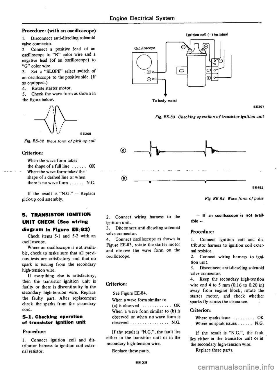
Connect
a
positive
lead
of
an
oscilloscope
to
R
olor
wire
and
a
negative
lead
of
an
oscilloscope
to
G
color
wire
3
Set
a
SLOPE
select
switch
of
an
oscilloscope
to
the
positive
side
If
so
equipped
4
Rotate
starter
motor
5
Check
the
wave
form
as
shown
in
the
figure
below
EE268
Fig
EE
82
Wave
form
of
pick
up
coil
Criterion
When
the
wave
form
takes
the
shape
of
a
full
line
OK
When
the
wave
form
takes
the
shape
of
a
dashed
line
or
when
there
is
no
wave
form
N
G
If
the
result
is
N
G
Replace
pick
up
coil
assembly
5
TRANSISTOR
IGNITION
UNIT
CHECK
See
wiring
diagram
In
Figure
EE
92
Check
items
5
1
and
5
2
with
an
oscilloscope
Where
an
oscilloscope
is
not
availa
ble
check
to
make
sure
that
all
previ
ous
tests
are
satisfactory
and
that
no
spark
is
issuing
from
the
secondary
high
tension
wire
If
everything
else
is
satisfactory
then
the
transistor
ignition
unit
is
faulty
or
there
is
discontinuity
in
the
secondary
high
tension
wire
Replace
the
faulty
part
After
replacement
check
the
sparks
from
the
secondary
cord
5
1
Checking
operatIon
of
transIstor
Ignition
unit
Procedure
I
Connect
ignition
coil
and
dis
tributor
harness
to
ignition
coil
exter
nal
resistor
Engine
Electrical
System
Oscilloscope
o
EB
80
To
body
metal
Ignition
coil
terminal
8W
r
8
0
C
0
EB
Fig
EE
83
Checking
operation
of
transistor
ignition
unit
EE307
@
@
2
Connect
wiring
harness
to
the
ignition
unit
3
Disconnect
anti
dieseling
solenoid
valve
connector
4
Connect
oscilloscope
as
shown
in
Figure
EE
83
rotate
the
starter
motor
and
observe
the
wave
form
on
the
oscilloscope
Criterion
See
Figure
EE
84
When
a
wave
form
similar
to
a
is
observed
OK
When
a
wave
form
similar
to
b
is
obseIVed
or
when
no
wave
form
is
observed
N
G
If
the
result
is
N
G
the
fault
lies
either
in
the
transistor
unit
or
in
the
secondary
high
tension
wire
Replace
these
parts
EE
39
EE452
Fig
EE
84
W
uve
form
of
pulse
If
an
oscilloscope
is
not
avail
able
Procedure
1
Connect
ignition
coil
and
dis
tributor
harness
to
ignition
coil
exter
nal
resistor
2
Connect
wiring
harness
to
igni
tion
unit
3
Disconnect
anti
dieseling
solenoid
valve
connector
4
Keep
the
secondary
high
tension
wire
end
4
to
5
mm
0
16
to
0
20
in
away
from
engine
block
rotate
the
starter
motor
and
check
whether
sparks
fly
across
the
clearance
Criterion
Where
sparks
issue
OK
Where
no
spark
issues
N
G
If
the
result
is
N
G
the
fault
lies
either
in
the
transistor
unit
or
in
the
secondary
high
tension
wire
Replace
these
paris
Page 207 of 537
5
2
Checking
operation
of
duty
Procedure
Connect
anti
dieseling
solenoid
valve
connector
2
While
the
engine
is
idling
observe
the
wave
ronn
on
the
oscilloscope
in
the
same
way
as
stated
in
item
5
Figure
EE
83
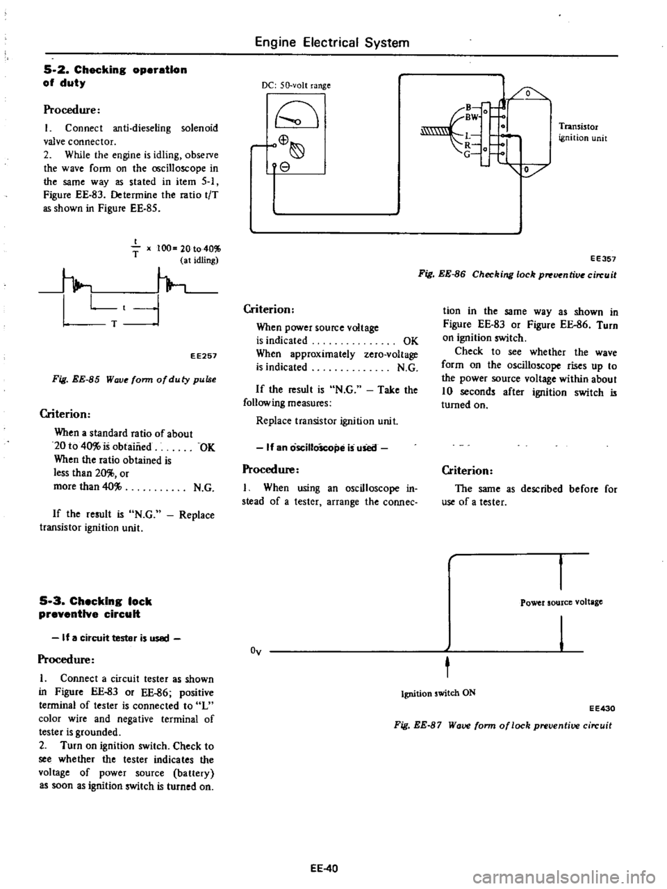
Determine
the
ratio
tiT
as
shown
in
Figure
EE
85
I
T
x
100
20
to
401
1
at
idling
h
Lt
1
T
EE257
Fig
EE
85
Wove
form
ofduty
pulse
Criterion
When
a
standard
ratio
of
about
20
to
40
is
obtaiiied
OK
When
the
ratio
obtained
is
less
than
20
or
more
than
40
N
G
If
the
result
is
N
G
transistor
ignition
unit
Replace
5
3
Checking
lock
preventive
circuit
If
a
circuit
tester
is
used
Procedure
1
Connect
a
circuit
tester
as
shown
in
Figure
EE
83
or
EE
86
positive
terminal
of
tester
is
connected
to
L
color
wire
and
negative
terminal
of
tester
is
grounded
2
Turn
on
ignition
switch
Check
to
see
whether
the
tester
indicates
the
vol
age
of
power
source
ba
t1ery
as
soon
as
ignition
switch
is
turned
on
Engine
Electrical
System
DC
50
volt
range
rC
o
8
Criterion
When
power
source
voltage
is
indicated
When
approximately
is
indicated
OK
zero
voltage
N
G
If
the
result
is
N
G
Take
the
following
measures
Replace
transistor
ignition
unit
If
an
oscilloScope
is
uSetl
Procedure
I
When
using
an
oscilloscope
in
stead
of
a
tester
arrange
the
connec
Oy
EE
40
B
fJ
BW
O
L
t
1
V
Transi
tor
ignition
unit
EE357
Fig
EE
86
Checking
lock
p
uentive
circuit
tion
in
the
same
way
as
shown
in
Figure
EE
83
or
Figure
EE
86
Turn
on
ignition
switch
Check
to
see
whether
the
wave
form
on
the
oscilloscope
rises
up
to
the
power
source
voltage
within
about
10
seconds
after
ignition
switch
is
turned
on
Criterion
The
same
as
described
before
for
use
of
a
tester
Power
source
voltage
t
Ignition
switch
ON
EE430
Fig
EE
87
Wave
form
of
lock
preventive
circuit