lock DATSUN PICK-UP 1977 Workshop Manual
[x] Cancel search | Manufacturer: DATSUN, Model Year: 1977, Model line: PICK-UP, Model: DATSUN PICK-UP 1977Pages: 537, PDF Size: 35.48 MB
Page 128 of 537
Engine
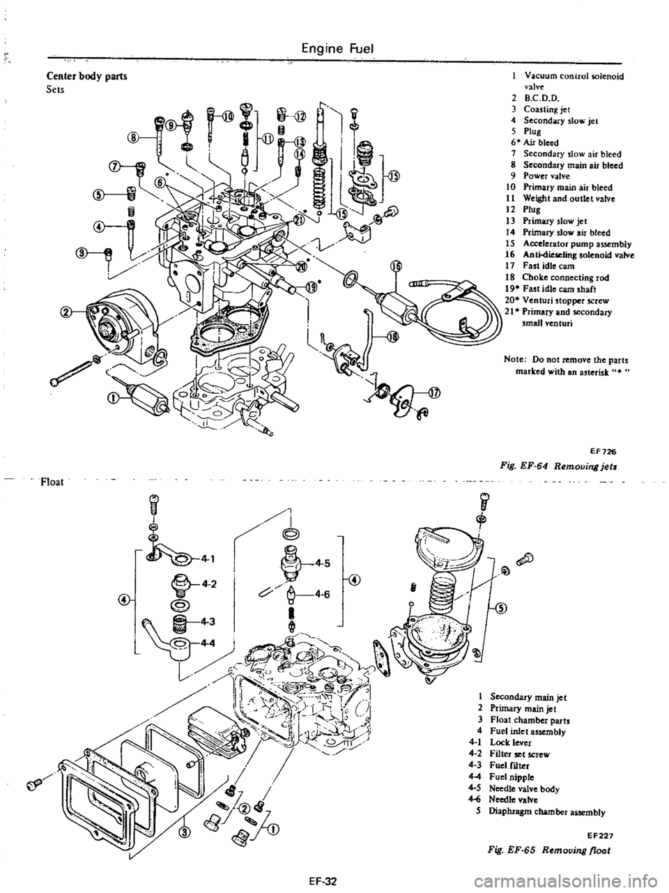
Fuel
1
l
@
Vacuum
control
solenoid
valve
2
B
C
D
D
3
Coasting
jet
4
Secondary
slow
jet
5
ptug
6
Air
bleed
1
Secondary
slow
air
bleed
8
Secondary
main
air
bleed
9
Power
valve
10
Primary
main
air
bleed
11
Weight
and
outlet
valve
12
ptug
13
Primary
slow
jet
14
Ptirnar
slow
air
bleed
15
Accelerator
pump
assembly
16
AntkUeselingsolenoid
vain
17
Fast
idle
earn
18
Chok
e
connecting
rod
19
Fast
idle
earn
shaft
20
Ventuci
stopper
screw
21
Primary
and
secondary
small
venturi
Center
body
parts
Sets
Note
Do
not
remove
the
parts
marked
with
an
asterisk
It
EF726
Fig
EF
64
Removing
jets
Float
I
i
@
i
j
1
L
4
2
V
4
S
@
c
4
6
e4
11
Qll
1D
Yr
J
1
t
t
1
lil
c
@5
1
p
u
I
r
i
r
1
CJi
U
7
to1
8rtj
lv
Ji
JlJ
if
I
1
2
3
4
4
1
4
2
4
3
44
4
5
Hi
5
Secondary
main
jet
Primary
main
jet
Float
chamber
parts
Fuel
inlet
assembly
Lock
lever
Filter
set
screw
Fuel
f1Iter
Fuel
nipple
Needle
valve
body
Needle
valve
Diaphragm
chamber
aiSembly
EF227
Fig
EF
65
Removing
float
EF
32
Page 130 of 537
CLEANING
AND
INSPECTION
Dirt
gum
wuler
or
l
arbon
con
taminatiun
in
or
on
exterior
moving
parts
of
a
arburctor
arc
often
respon
sihk
for
unsatisfactory
performance
For
this
reason
efficient
carbutetioll
dcpends
upon
careful
cleaning
and
inspection
while
servicing
I
Blow
all
passages
and
castings
with
compressed
air
and
blow
off
all
parts
until
dry
Note
Do
not
pass
drills
or
wires
through
calibrated
jet
or
passaaa
as
this
may
enlarge
orirlce
and
seriously
affect
carburetor
calibrs
lion
2
Check
all
parts
for
wear
If
wear
is
noted
damaged
parts
must
be
re
placed
Note
especially
the
following
Engine
Fuel
I
Check
float
needle
and
seat
for
wear
If
wear
is
noted
assembly
must
be
replaced
2
Check
throule
and
choke
shaft
bores
in
throtlle
chamber
and
choice
chamber
for
wear
or
out
of
roundness
3
Inspect
idle
adjusting
needle
for
burrs
or
ridges
Such
a
condition
re
quires
replacemen
1
3
Inspect
gaskets
0
see
if
they
appear
hard
or
briUle
or
if
edges
are
torn
or
distorted
If
any
such
condi
tion
i
noted
they
must
be
replaced
4
Check
filter
screen
for
dirt
or
lint
Clean
and
if
screen
is
distorted
or
remain
plugged
replace
5
Check
linkage
for
operating
condition
6
Inspect
operation
of
accelerating
pump
Pour
f
el
into
jloat
chamber
and
make
throtlle
lever
operate
Check
condition
of
fuel
injection
from
the
EF
34
accelerating
nowe
7
Push
connecting
rod
of
dia
phragm
chamber
and
block
passage
of
vacuum
with
finger
When
connecting
rod
becomes
free
check
for
leakage
of
air
or
damage
to
diaphragm
Jets
Carburetor
performance
depends
on
jet
and
air
bleed
That
is
why
these
components
must
be
fabricated
with
utmost
care
To
clean
them
use
cleaning
solvent
and
blow
air
on
them
Larger
inner
numbers
tamped
on
the
jet
indicate
larger
diameters
Ac
cordingly
main
and
slow
jets
with
lalger
nUmbers
provide
richer
mixture
the
smaller
the
numbers
the
leaner
the
mixture
Conversely
the
main
and
slow
air
bleeds
through
which
air
to
passes
through
make
the
fueLleaner
if
they
bear
larger
numbers
the
smaller
the
numbers
the
richer
the
fuel
Page 139 of 537
Emission
Control
System
EARLY
FUEL
EVAPORATIVE
SYSTEM
E
F
E
DESCRIPTION
spring
and
counterweight
which
are
assembled
on
the
valve
shaft
projecting
to
the
rear
outside
of
the
exhaust
manifold
The
counterweight
is
se
cured
to
the
valve
shaft
with
key
bolt
and
snap
ring
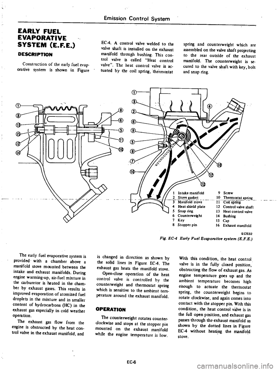
EC
4
A
control
valve
welded
to
the
valve
shaft
is
wtalled
on
the
exhaust
manifold
through
bushing
This
con
trol
valve
is
called
Heat
control
valve
The
heat
control
valve
is
ac
luated
by
the
coil
spring
thermostat
Construction
of
the
early
fuel
evap
orative
system
is
shown
in
Figure
r
I
1
@
rW
9
Sc
w
10
Thennostat
spring
11
Coil
spriiig
12
Control
valve
shaft
13
Heat
control
valve
14
Bushing
15
Cap
16
Exhaust
manifold
1
Intake
manifold
2
Stove
gasket
ManifoktstOve
4
Heat
shield
plate
5
Snap
ring
6
Counterweight
7
Key
g
Stoppel
pin
EC532
Fig
EC
4
Early
Fuel
Evaporutive
tem
E
F
E
The
early
fuel
evaporative
system
is
provided
with
a
chamber
above
a
manifold
stove
moonted
between
the
intake
and
exhaust
manifolds
During
engine
warming
up
air
fuel
mixture
in
the
carburetor
is
heated
in
the
cham
bet
by
exhaust
gases
This
results
in
improved
evaporation
of
atomized
fuel
droplets
in
the
mixture
and
in
smaller
content
of
hydrocarbons
He
in
the
exhaust
gas
especially
in
cold
weather
operation
The
exhaust
gas
flow
from
the
engine
is
obstructed
by
the
heat
con
trol
valve
in
the
exhaust
manifold
and
is
changed
in
direction
as
shown
by
the
solid
lines
in
Figure
EC
4
The
exhaust
gas
heats
the
manifold
stove
Open
close
operation
of
the
heat
control
valve
is
controlled
by
the
counterweight
and
thermostat
spring
which
is
sensitive
to
the
ambient
tem
perature
around
the
exhaust
manifold
With
this
condition
the
heat
control
valve
is
in
the
fully
closed
position
obstructing
the
flow
of
exhaust
gas
As
engine
tempera
lure
goes
up
and
the
ambient
temperature
becomes
high
enough
to
actuate
the
thermostat
spring
the
counterweight
begins
to
rotate
clockwise
and
again
comes
into
con
tact
with
the
stopper
pin
With
this
condition
the
heat
control
valve
is
in
the
full
open
position
and
exhaust
gas
passes
through
the
exhaust
manifold
as
shown
by
the
dotted
lines
in
Figure
EC
4
without
heati
ng
the
manifold
stove
OPERATION
The
counterweight
rotates
counter
clockwise
and
stops
at
the
stopper
pin
mounted
on
the
exhaust
manifold
while
the
engine
temperature
is
low
EC
6
Page 140 of 537
REMOVAL
AND
INSTAUATION
Emission
Control
System
EC533
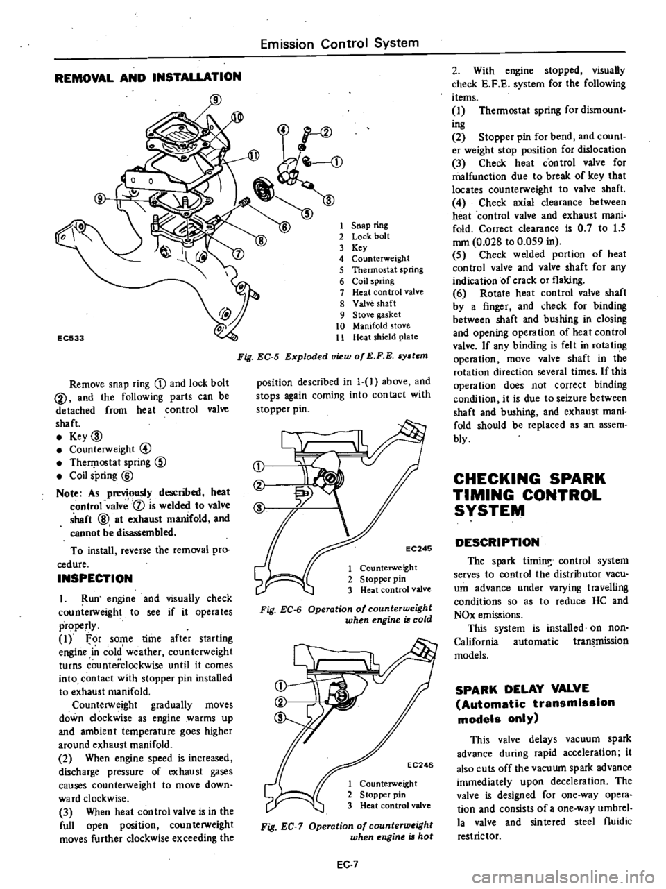
Remove
snap
ring
D
and
lock
bolt
@
and
the
following
parts
can
be
detached
from
heat
control
valve
shaft
Key
00
Counterweight
@
TherI
lostat
spring
CID
Coil
spring
@
Note
As
previously
descnoed
heat
control
valv
1
is
welded
to
valve
shaft
@
at
exhaust
manifold
and
cannot
be
disassembled
To
install
reverse
the
removal
pro
cedure
INSPECTION
I
Run
engine
and
visually
check
counterweight
to
see
if
it
operates
properly
1
For
some
time
after
starling
engine
in
cold
weather
counterweight
turns
counterclockwise
until
it
comes
into
contact
with
stopper
pin
installed
to
exhaust
manifold
Counterweight
gradually
moves
down
clockwise
as
engine
warms
up
and
ambient
temperature
goes
higher
around
exhaust
manifold
2
When
engine
speed
is
increased
discharge
pressure
of
exhaust
gases
causes
counterweight
to
move
down
ward
clockwise
3
When
heat
con
trol
valve
is
in
the
full
open
position
coun
terweight
moves
further
clockwise
exceeding
the
1
Snap
ring
2
Lock
bolt
3
Key
4
Counterweight
5
Thermostat
spring
6
Coil
spring
7
Heat
control
valve
8
Valve
shaft
9
Stove
gasket
10
Manifold
stove
11
Heat
shield
plate
Fig
EC
5
Exploded
view
of
E
F
E
stem
position
described
in
1
1
above
and
stops
again
coming
into
con
tact
with
stopper
pin
j
EC246
1
Counterweight
2
S
topper
pin
3
Heat
control
valve
Fig
EC
6
Operation
of
counterweight
when
engine
is
cold
EC246
1
Counterweight
2
Stopper
pin
3
Heat
control
valve
Fig
EC
7
Operation
of
counterw
ight
when
ngine
is
hot
EC
7
2
With
engine
stopped
visually
check
E
F
E
system
for
the
following
items
1
Thermostat
spring
for
dismount
ing
2
Stopper
pin
for
bend
and
count
er
weight
stop
position
for
dislocation
3
Check
heat
control
valve
for
malfunction
due
to
break
of
key
that
locates
counterweight
to
valve
shaft
4
Check
axial
clearance
between
heat
control
valve
and
exhaust
mani
fold
Correct
clearance
is
0
7
to
1
5
mm
0
028
to
0
059
in
5
Check
welded
portion
of
heat
control
valve
and
valve
shaft
for
any
indication
of
crack
or
flaking
6
Rotate
heat
control
valve
shaft
by
a
finger
and
check
for
binding
between
shaft
and
bushing
in
closing
and
opening
operation
of
heat
control
valve
If
any
binding
is
felt
in
rotating
operation
move
valve
shaft
in
the
rotation
direction
several
times
If
this
operation
does
not
correct
binding
condition
it
is
due
to
seizure
between
shaft
and
bushing
and
exhaust
mani
fold
should
be
replaced
as
an
assem
bly
CHECKING
SPARK
TIMING
CONTROL
SYSTEM
DESCRIPTION
The
spark
tirnin
control
system
serves
to
control
the
distributor
vacu
um
advance
under
varying
travelling
conditions
so
as
to
reduce
HC
and
NOx
emissions
This
system
is
installed
on
non
California
automatic
transmission
models
SPARK
DELAY
VALVE
Automatic
transmission
models
only
This
valve
delays
vacuum
spark
advance
during
rapid
acceleration
it
also
cuts
off
the
vacuwn
spark
advance
immediately
upon
deceleration
The
valve
is
designed
for
one
way
opera
tion
and
consists
of
a
one
way
umbrel
la
valve
and
sinlered
steel
fluidic
restrictor
Page 156 of 537
1
1
I
I
I
1
v
v
I
I
I
I
I
I
I
I
I
I
I
I
I
I
I
I
I
I
I
I
I
L
0
I
Magnet
coil
Detector
drive
counter
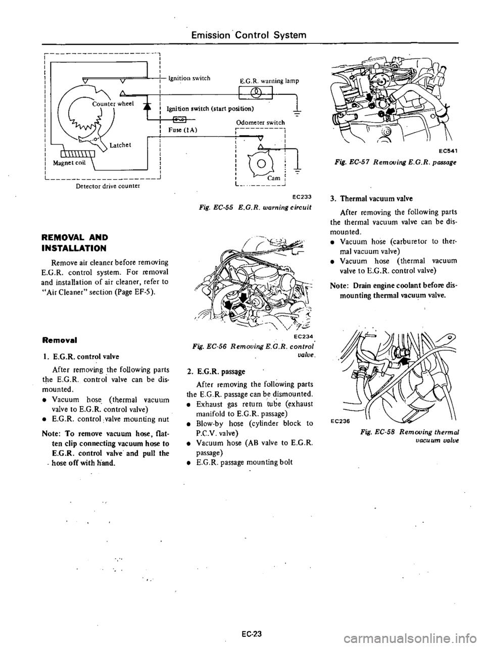
REMOVAL
AND
INSTALLATION
Remove
air
cleaner
before
removing
E
G
R
control
system
For
removal
and
installation
of
air
cleaner
refer
to
Air
Cleaner
section
Page
EF
S
Removal
I
E
G
R
control
valve
After
removing
the
following
parts
the
E
G
R
controi
valve
can
be
dis
mounted
Vacuum
hose
thermal
vacuum
valve
to
E
G
R
control
valve
E
G
R
control
valve
mounting
nut
Note
To
remove
vacuum
hose
flat
ten
clip
connecting
vacuum
hose
to
E
G
R
control
valve
and
pull
the
hose
off
with
hand
Emission
Control
System
Ignition
switch
E
G
R
warning
lamp
f
1
Ignition
switch
start
position
Fuse
1
A
Odometer
switch
r
I
I
I
I
v
I
I
I
i
lQ
U
1
mi
L
J
EC233
Fig
EC
55
E
G
R
warning
circuit
EC234
Fig
EC
56
Removing
KG
R
control
valve
2
E
G
R
pass
ge
After
removing
the
following
parts
the
E
G
R
passage
can
be
dismounted
Exhaust
gas
return
tube
exhaust
manifold
to
E
G
R
passage
B1ow
by
hose
cylinder
block
to
P
C
v
valve
Vacuum
hose
AB
valve
to
E
G
R
passage
E
G
R
passage
mounting
bolt
EC
23
EC541
Fig
EC
57
Removing
E
G
R
passage
3
Thermal
vacuum
valve
After
removing
the
following
parts
the
thermal
vacuum
valve
can
be
dis
mounted
Vacuum
hose
carburetor
to
ther
mal
vacuum
valve
Vacuum
hose
thermal
vacuum
valve
to
E
G
R
control
valve
Note
Drain
engine
coolant
before
dis
mounting
thermal
vacu
m
valve
Fig
EC
58
Removing
thermal
vacu
um
valve
Page 160 of 537
REMOVAL
AND
INSPECTION
Removal
and
inspection
can
be
done
as
follows
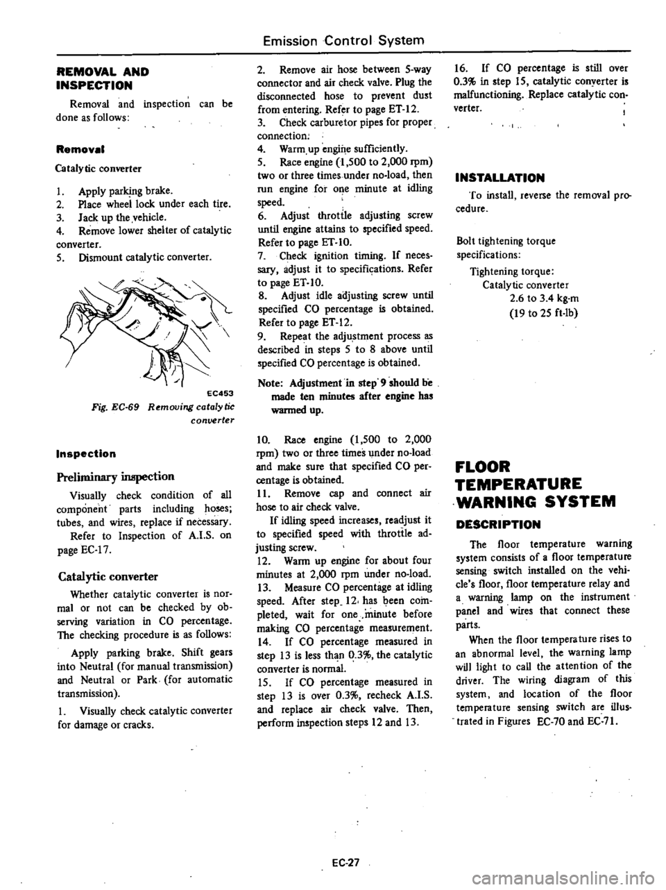
Removal
Catalytic
converter
1
Apply
parking
brake
2
Place
wheel
lock
under
each
tire
3
Jack
up
the
vehicle
4
Remove
lower
shelter
of
catalytic
converter
5
Dismount
catalytic
converter
EC453
Fig
EC
69
Removing
catalytic
conuerter
Inspection
Preliminary
inspection
Visually
check
condition
of
all
component
parts
including
ho
s
tubes
and
wires
replace
if
necessary
Refer
to
Inspection
of
A
I
S
on
page
EC
17
Catalytic
converter
Whether
catalytic
converter
is
nor
mal
or
not
can
be
checked
by
ob
serving
variation
in
CO
percentage
The
checking
procedure
is
as
follows
Apply
parking
brake
Shift
gears
into
Neutral
for
manual
transmission
and
Neutral
or
Park
for
automatic
transmission
1
Visually
check
catalytic
converter
for
damage
or
cracks
Emission
Control
System
2
Remove
air
hose
between
5
way
connector
and
air
check
valve
Plug
the
disconnected
hose
to
prevent
dust
from
entering
Refer
to
page
ET
12
3
Check
carburetor
pipes
for
proper
connection
4
Warm
up
engine
sufficiently
5
Race
engine
1
500
to
2
000
rpm
two
or
three
times
under
no
load
then
run
engine
for
o
e
minute
at
idling
speed
6
Adjust
throttle
adjusting
screw
until
engine
attains
to
specified
speed
Refer
to
page
ET
10
7
Check
ignition
timing
If
neces
sary
adjust
it
to
specifkations
Refer
to
page
ET
10
B
Adjust
idle
adjusting
screw
until
specified
CO
percentage
is
obtained
Refer
to
page
ET
12
9
Repeat
the
adju
stment
process
as
described
in
steps
5
to
8
above
until
specified
CO
percentage
is
obtained
Note
Adjustment
in
step
9
should
be
made
ten
minutes
after
engine
has
wanned
up
10
Race
engine
1
500
to
2
000
rpm
two
or
three
times
under
no
load
and
make
sure
that
specified
CO
per
centage
is
obtained
11
Remove
cap
and
connect
air
hose
to
air
check
valve
If
idling
speed
increases
readjust
it
to
specified
speed
with
throttle
ad
justing
screw
12
WaRn
up
engine
for
about
four
minutes
at
2
000
rpm
under
no
load
13
Measure
CO
percentage
at
idling
speed
After
step
12
has
been
coin
pleted
wait
for
one
minute
before
making
CO
percentage
measurement
14
If
CO
percentage
measured
in
step
13
is
less
than
0
3
the
catalytic
converter
is
normal
15
If
CO
percentage
measured
in
step
13
is
over
0
3
recheck
A
I
S
and
replace
air
check
valve
Then
perform
inspection
steps
12
and
13
EC
27
16
If
CO
percentage
is
still
over
0
3
in
step
15
catalytic
conyerter
is
malfunctioning
Replace
catalytic
con
verter
INSTALLATION
To
install
reverse
the
removal
pro
cedure
Bolt
lightening
torque
specifications
Tightening
torque
Catalytic
converter
2
6
to
3
4
kg
m
19
to
25
ft
Ib
FLOOR
TEMPERATURE
WARNING
SYSTEM
DESCRIPTION
The
floor
temperature
warning
system
consists
of
a
floor
temperature
sensing
switch
installed
on
the
vehi
cle
s
floor
floor
temperature
relay
and
a
warning
lamp
on
the
instrument
panel
and
wires
that
connect
these
parts
When
the
floor
tempera
ture
rises
to
an
abnormal
level
the
warning
lamp
will
light
to
call
the
attention
of
the
driver
The
wiring
diagram
of
this
system
and
location
of
the
floor
temperature
sensing
switch
are
ilIus
trated
in
Figures
EC
70
and
EC
71
Page 165 of 537

sufficient
delivery
of
fuel
to
engine
or
vapor
lock
It
must
therefore
be
1
3
connectur
COCk
Air
Manometer
Emission
Control
System
repaired
or
replaced
368
mmH20
14
5
inH20
LL
IPO
liqUid
epo
o
36
r
@
Carbon
canister
EC786
Fig
EC
79
Checking
evaporative
emmion
control
syatem
CARBON
CANISTER
PURGE
CONTROL
VALVE
Check
for
fuel
vapor
leakage
in
the
distributor
vacuum
line
at
diaphragm
of
carbon
canister
purge
control
valve
To
check
for
leakage
proceed
as
follows
I
Disconnect
rubber
hose
in
the
line
between
T
connector
and
carbon
canister
at
T
connector
2
Inhale
air
into
the
opening
of
rubber
hose
running
to
vacuum
hole
in
carbon
canister
and
ensure
that
there
is
no
leak
ET349
Fig
EC
so
Checking
carbon
canuter
purge
control
valve
3
If
there
is
a
leak
remove
top
cover
from
purge
control
valve
and
check
for
dislocated
or
cracked
dia
phragm
If
necessary
replace
dia
phragm
kit
which
is
made
up
of
a
retainer
a
diaphragm
and
a
spring
@
@
1
Cover
2
Diaphragm
3
Retainer
4
Spring
ET350
Fig
EC
81
Carbon
catU
ter
purge
control
valve
CARBON
CANISTER
FILTER
Check
for
a
contaminated
element
Element
can
be
removed
at
the
bottom
of
canister
installed
on
vehicle
body
EC
32
ET37Q
Fig
EC
s2
Replacing
carbon
canuter
filter
FUEL
TANK
VACUUM
RELIEF
VALVE
Remove
fuel
filler
cap
and
see
it
functions
properly
I
Wipe
clean
valve
housing
and
have
it
in
your
mouth
2
Inhale
air
A
slight
resistance
ac
companied
by
valve
indicates
that
valve
is
in
good
mechanical
condition
Note
also
that
by
further
inhaling
air
the
resistance
should
be
disappeared
with
valve
clicks
3
If
valve
is
clogged
or
if
no
resist
ance
is
felt
replace
cap
as
an
assem
bled
uni
t
l
u
ET369
Fig
EC
83
Fuel
filler
cap
Page 173 of 537
OPERATION
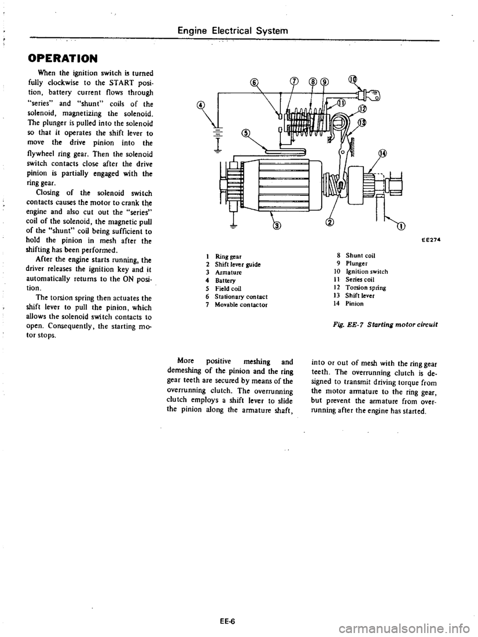
When
the
ignition
switch
turned
fully
clockwise
to
the
START
posi
tion
battery
current
flows
through
series
and
shunt
coils
of
the
solenoid
magnetizing
the
solenoid
The
plunger
is
pulled
into
the
solenoid
so
that
it
operates
the
shift
lever
to
move
the
drive
pinion
into
the
flywheel
ring
gear
Then
the
solenoid
switch
contacts
close
after
the
drive
pinion
is
partially
engaged
with
the
ring
gear
Closing
of
the
solenoid
switch
contacts
c
uses
the
motor
to
crank
the
engine
and
also
cut
out
the
series
coil
of
the
solenoid
the
magnetic
pull
of
the
shunt
coil
being
sufficient
to
hold
the
pinion
in
mesh
after
the
shifting
has
been
performed
After
the
engine
starts
running
the
driver
releases
the
ignition
key
and
it
automatically
returns
to
the
ON
posi
tion
The
torsion
spring
then
actuates
the
shift
lever
to
pull
the
pinion
which
allows
the
solenoid
swi
tch
contacts
to
open
Consequently
the
starting
mo
tor
stops
Engine
Electrical
System
I
I
Ring
gear
2
Shift
lever
guide
3
Armature
4
Battery
5
Field
coil
6
Stationary
contact
7
Monble
contactor
More
positive
meshing
and
demeshing
of
the
pinion
and
the
ring
gear
teeth
are
secured
by
means
of
the
overrunning
clutch
The
overruIUling
clutch
employs
a
shift
lever
to
slide
the
pinion
along
the
armature
shaft
EE
6
F
l
cp
o
r
1
I
I
W
m
EE274
8
Shunt
coil
9
Plunger
10
Ignition
switch
11
Series
coil
12
Torsion
spring
13
Shift
lever
14
Pinion
Fig
EE
7
Starting
motor
circuit
into
or
out
of
mesh
with
the
ring
gear
teeth
The
overrunning
clutch
is
de
signed
to
transmit
driving
torque
from
the
motor
armature
to
the
ring
gear
but
prevent
the
armature
from
over
running
after
the
engine
has
started
Page 178 of 537

Engine
Electrical
System
SERVICE
DATA
AND
SPECIFICATIONS
Type
System
voltage
No
load
Terminal
voltage
Current
Revolution
v
V
A
rpm
Brush
length
Outer
diameter
of
commutator
mm
in
mm
in
Brush
spring
tension
kg
Ib
Clearance
between
bearing
metal
and
armature
shaft
mm
in
Clearance
L
between
pinion
front
edge
and
pinion
stopper
mm
in
TROUBLE
DIAGNOSES
AND
CORRECTIONS
Condition
Starting
motor
will
not
operate
Noisy
starting
motor
Starting
motor
cranks
slowly
Probable
cause
Discharged
battery
Damaged
solenoid
switch
Loose
connections
of
terminal
Damaged
brushes
Starti
g
motor
inoperative
Loose
securing
bolt
Worn
pinion
gear
Poor
lubrication
Worn
commutator
Worn
brushes
Discharged
battery
Loose
connection
of
terminal
Worn
brushes
Locked
brushes
EE
ll
Manual
transmission
Automatic
transmission
Optional
for
manual
transmission
SII4
ISOB
S114
170B
12
12
Less
than
60
More
than
7
000
More
than
6
000
More
than
39
1
54
More
than
12
0
47
1
4
to
I
S
3
1
to
4
0
Less
than
0
2
O
OOS
0
3
to
1
5
0
012
to
0
059
Corrective
action
Charge
or
replace
battery
Repair
or
replace
solenoid
switch
Clean
and
tighten
terminal
Replace
brushes
Remove
starting
motor
and
make
test
Tighten
Replace
Add
oil
Replace
Replace
Charge
Clean
and
tighten
Replace
Inspect
brush
spring
tension
or
repair
brush
holder
Page 179 of 537
Condition
Engine
Electrical
System
Probable
cause
Starting
motor
cranks
slowly
Dirty
or
worn
commutator
Armature
rubs
field
coil
Damaged
solenoid
switch
Starting
motor
operates
but
does
not
crank
engine
Worn
pinion
Locked
pinion
guide
Worn
ring
gear
Starting
motor
will
not
disengage
even
if
ignition
switch
is
turned
off
Damaged
solenoid
switch
Damaged
gear
teeth
The
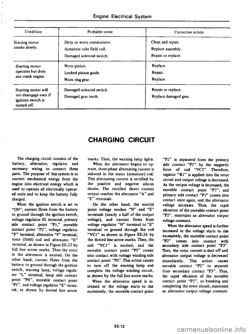
charging
circuit
consists
of
the
battery
alternator
regulator
and
necessary
wiring
to
connect
these
parts
The
purpose
of
this
system
is
to
convert
mechanical
energy
from
the
engine
into
electrical
energy
which
is
used
to
operate
all
electrically
operat
ed
units
and
to
keep
the
battery
fully
charged
When
the
ignition
switch
is
set
to
ON
current
flows
from
the
battery
to
ground
through
the
ignition
switch
voltage
regulator
IG
terminal
primary
side
contact
point
PI
movable
contact
point
P2
voltage
regulator
IF
terminal
alternator
IF
terminal
rotor
field
coil
and
alternator
E
terminal
as
shown
in
Figure
EE
23
by
full
line
arrow
marks
Then
the
rotor
in
the
alternator
is
excited
On
the
other
hand
current
flows
from
the
battery
to
ground
through
the
ignition
switch
warning
lamp
voltage
regula
tor
L
terminal
lamp
side
contact
point
P4
movable
contact
point
P5
and
voltage
regulator
E
termi
nal
as
shown
by
dotted
line
arrow
CHARGING
CIRCUIT
marks
Then
the
warning
lamp
lights
When
the
alternator
begins
to
op
erate
three
phase
alternating
current
is
induced
in
the
stator
armature
coil
This
alternating
current
is
rectified
by
the
positive
and
negative
silicon
diodes
The
rectified
direct
current
output
reaches
the
alternator
A
and
E
terminals
On
the
other
hand
the
neutral
point
voltage
reaches
N
and
E
terminals
nearly
a
half
of
the
output
voltage
and
current
flows
from
voltage
regulator
N
terminal
to
E
terminal
or
ground
through
the
coil
VCI
as
shown
in
Figure
EE
24
by
the
dotted
line
arrow
marks
Then
the
coil
VCI
is
excited
and
the
movable
contact
point
IPS
comes
into
contact
with
voltage
winding
side
contact
point
P6
This
action
causes
to
turn
off
the
warning
lamp
and
complete
the
voltage
winding
circuit
as
shown
by
the
full
line
arrow
marks
When
the
alternator
speed
is
in
creased
or
the
voltage
starts
to
rise
excessively
the
movable
contact
point
EE
12
Corrective
action
Clean
and
repair
Replace
assembly
Repair
or
replace
Replace
Repair
Replace
Repair
or
replace
Replace
damaged
gear
P2
is
separated
from
the
primary
side
contact
PI
by
the
magnetic
force
of
coil
VC2
Therefore
registor
RI
is
applied
into
the
rotor
circuit
and
output
voltage
is
decreased
AJ
the
output
voltage
is
decreased
the
movable
contact
point
P2
and
primary
side
contact
Pin
comes
into
contact
once
again
and
the
alternator
voltage
increases
Thus
the
rapid
vibration
of
the
movable
contact
point
IPl
maintains
an
alternator
output
voltage
constant
When
the
alternator
speed
is
further
increased
or
the
voltage
starts
to
rise
excessively
the
movable
contact
point
P2
comes
into
contact
with
secondllJ
side
contact
point
P3
Then
the
rotor
current
is
shut
off
and
alternator
output
voltage
is
decreased
immediately
This
action
causes
movable
contact
n
to
separate
from
secondary
contact
P3
Thus
the
rapid
vibration
of
the
movable
contact
point
P2
or
breaking
and
completing
the
rotor
circuit
maintains
an
alternator
output
voltage
constant