DODGE RAM 2001 Service Repair Manual
Manufacturer: DODGE, Model Year: 2001, Model line: RAM, Model: DODGE RAM 2001Pages: 2889, PDF Size: 68.07 MB
Page 2091 of 2889
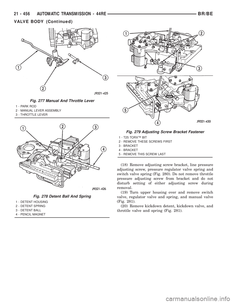
(18) Remove adjusting screw bracket, line pressure
adjusting screw, pressure regulator valve spring and
switch valve spring (Fig. 280). Do not remove throttle
pressure adjusting screw from bracket and do not
disturb setting of either adjusting screw during
removal.
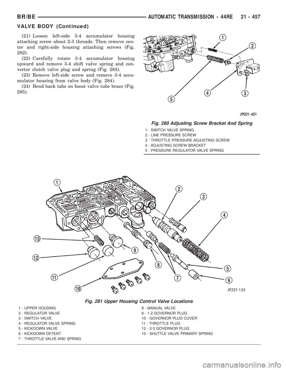
(19) Turn upper housing over and remove switch
valve, regulator valve and spring, and manual valve
(Fig. 281).
(20) Remove kickdown detent, kickdown valve, and
throttle valve and spring (Fig. 281).
Fig. 277 Manual And Throttle Lever
1 - PARK ROD
2 - MANUAL LEVER ASSEMBLY
3 - THROTTLE LEVER
Fig. 278 Detent Ball And Spring
1 - DETENT HOUSING
2 - DETENT SPRING
3 - DETENT BALL
4 - PENCIL MAGNET
Fig. 279 Adjusting Screw Bracket Fastener
1 - T25 TORXŸ BIT
2 - REMOVE THESE SCREWS FIRST
3 - BRACKET
4 - BRACKET
5 - REMOVE THIS SCREW LAST
21 - 456 AUTOMATIC TRANSMISSION - 44REBR/BE
VALVE BODY (Continued)
Page 2092 of 2889
(21) Loosen left-side 3-4 accumulator housing
attaching screw about 2-3 threads. Then remove cen-
ter and right-side housing attaching screws (Fig.
282).
(22) Carefully rotate 3-4 accumulator housing
upward and remove 3-4 shift valve spring and con-
verter clutch valve plug and spring (Fig. 283).
(23) Remove left-side screw and remove 3-4 accu-
mulator housing from valve body (Fig. 284).
(24) Bend back tabs on boost valve tube brace (Fig.
285).
Fig. 281 Upper Housing Control Valve Locations
1 - UPPER HOUSING 8 - MANUAL VALVE
2 - REGULATOR VALVE 9 - 1-2 GOVERNOR PLUG
3 - SWITCH VALVE 10 - GOVERNOR PLUG COVER
4 - REGULATOR VALVE SPRING 11 - THROTTLE PLUG
5 - KICKDOWN VALVE 12 - 2-3 GOVERNOR PLUG
6 - KICKDOWN DETENT 13 - SHUTTLE VALVE PRIMARY SPRING
7 - THROTTLE VALVE AND SPRING
Fig. 280 Adjusting Screw Bracket And Spring
1 - SWITCH VALVE SPRING
2 - LINE PRESSURE SCREW
3 - THROTTLE PRESSURE ADJUSTING SCREW
4 - ADJUSTING SCREW BRACKET
5 - PRESSURE REGULATOR VALVE SPRING
BR/BEAUTOMATIC TRANSMISSION - 44RE 21 - 457
VALVE BODY (Continued)
Page 2093 of 2889
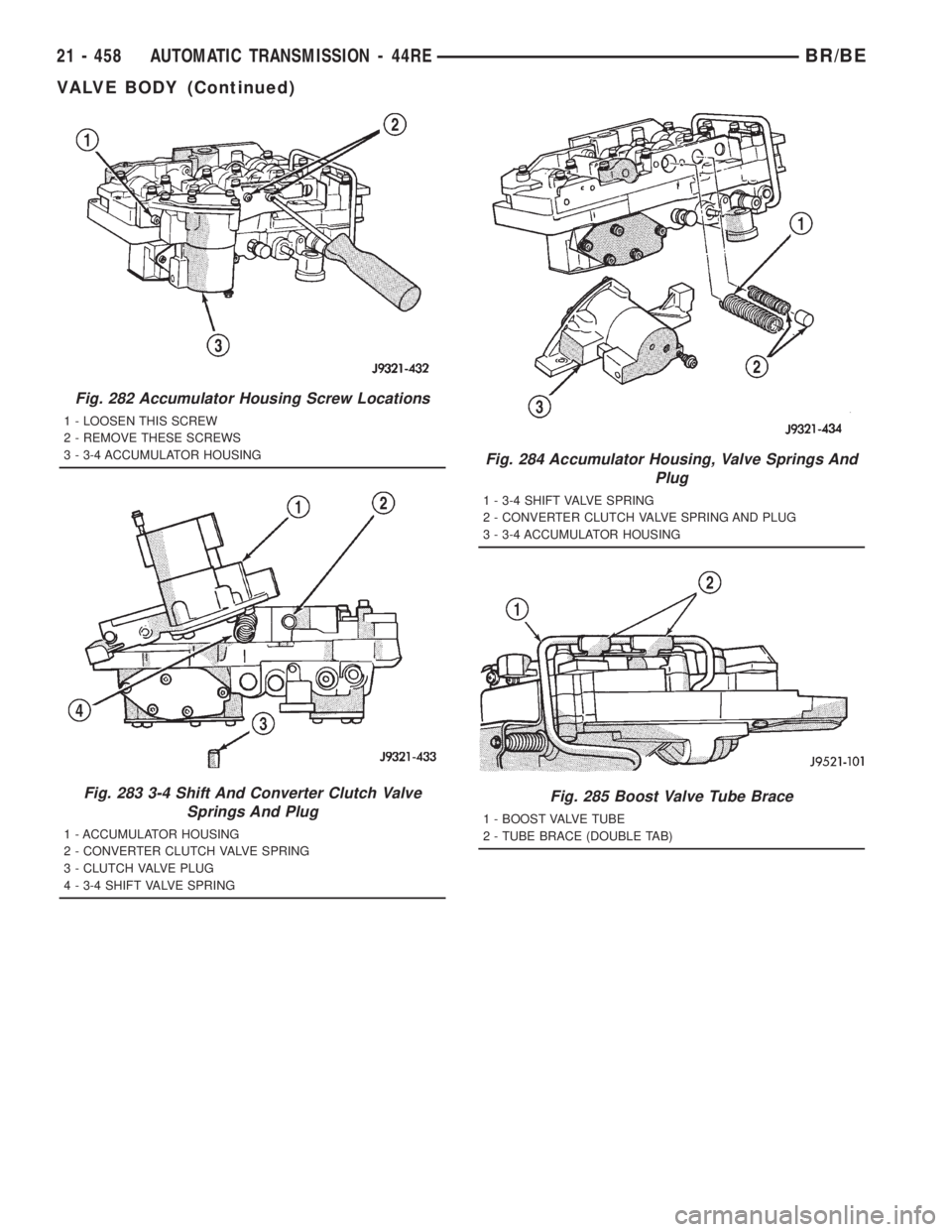
Fig. 282 Accumulator Housing Screw Locations
1 - LOOSEN THIS SCREW
2 - REMOVE THESE SCREWS
3 - 3-4 ACCUMULATOR HOUSING
Fig. 283 3-4 Shift And Converter Clutch Valve
Springs And Plug
1 - ACCUMULATOR HOUSING
2 - CONVERTER CLUTCH VALVE SPRING
3 - CLUTCH VALVE PLUG
4 - 3-4 SHIFT VALVE SPRING
Fig. 284 Accumulator Housing, Valve Springs And
Plug
1 - 3-4 SHIFT VALVE SPRING
2 - CONVERTER CLUTCH VALVE SPRING AND PLUG
3 - 3-4 ACCUMULATOR HOUSING
Fig. 285 Boost Valve Tube Brace
1 - BOOST VALVE TUBE
2 - TUBE BRACE (DOUBLE TAB)
21 - 458 AUTOMATIC TRANSMISSION - 44REBR/BE
VALVE BODY (Continued)
Page 2094 of 2889
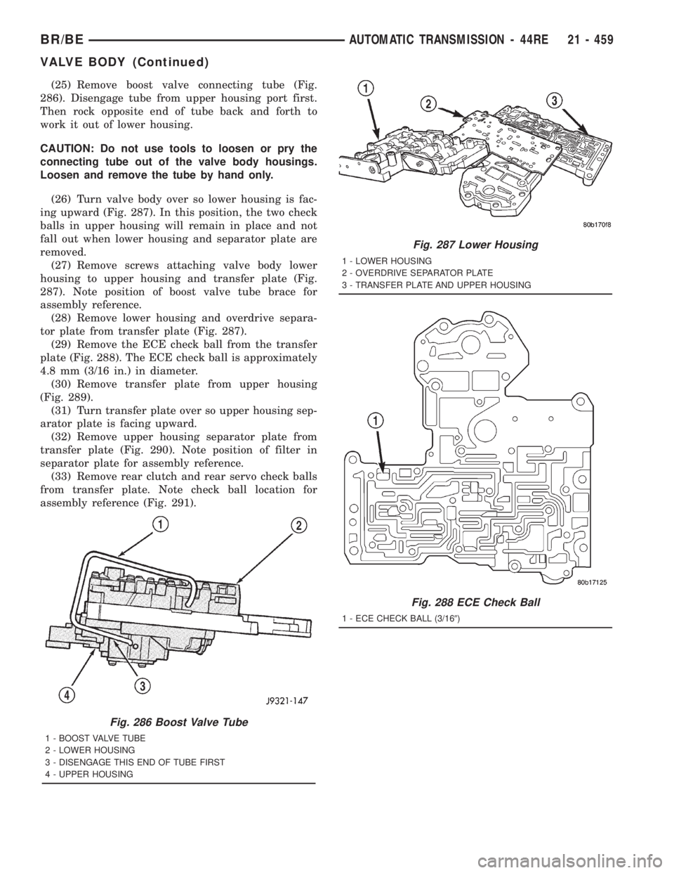
(25) Remove boost valve connecting tube (Fig.
286). Disengage tube from upper housing port first.
Then rock opposite end of tube back and forth to
work it out of lower housing.
CAUTION: Do not use tools to loosen or pry the
connecting tube out of the valve body housings.
Loosen and remove the tube by hand only.
(26) Turn valve body over so lower housing is fac-
ing upward (Fig. 287). In this position, the two check
balls in upper housing will remain in place and not
fall out when lower housing and separator plate are
removed.
(27) Remove screws attaching valve body lower
housing to upper housing and transfer plate (Fig.
287). Note position of boost valve tube brace for
assembly reference.
(28) Remove lower housing and overdrive separa-
tor plate from transfer plate (Fig. 287).
(29) Remove the ECE check ball from the transfer
plate (Fig. 288). The ECE check ball is approximately
4.8 mm (3/16 in.) in diameter.
(30) Remove transfer plate from upper housing
(Fig. 289).
(31) Turn transfer plate over so upper housing sep-
arator plate is facing upward.
(32) Remove upper housing separator plate from
transfer plate (Fig. 290). Note position of filter in
separator plate for assembly reference.
(33) Remove rear clutch and rear servo check balls
from transfer plate. Note check ball location for
assembly reference (Fig. 291).
Fig. 286 Boost Valve Tube
1 - BOOST VALVE TUBE
2 - LOWER HOUSING
3 - DISENGAGE THIS END OF TUBE FIRST
4 - UPPER HOUSING
Fig. 287 Lower Housing
1 - LOWER HOUSING
2 - OVERDRIVE SEPARATOR PLATE
3 - TRANSFER PLATE AND UPPER HOUSING
Fig. 288 ECE Check Ball
1 - ECE CHECK BALL (3/169)
BR/BEAUTOMATIC TRANSMISSION - 44RE 21 - 459
VALVE BODY (Continued)
Page 2095 of 2889
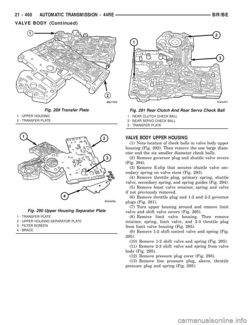
VALVE BODY UPPER HOUSING
(1) Note location of check balls in valve body upper
housing (Fig. 292). Then remove the one large diam-
eter and the six smaller diameter check balls.
(2) Remove governor plug and shuttle valve covers
(Fig. 294).
(3) Remove E-clip that secures shuttle valve sec-
ondary spring on valve stem (Fig. 293).
(4) Remove throttle plug, primary spring, shuttle
valve, secondary spring, and spring guides (Fig. 294).
(5) Remove boost valve retainer, spring and valve
if not previously removed.
(6) Remove throttle plug and 1-2 and 2-3 governor
plugs (Fig. 281).
(7) Turn upper housing around and remove limit
valve and shift valve covers (Fig. 295).
(8) Remove limit valve housing. Then remove
retainer, spring, limit valve, and 2-3 throttle plug
from limit valve housing (Fig. 295).
(9) Remove 1-2 shift control valve and spring (Fig.
295).
(10) Remove 1-2 shift valve and spring (Fig. 295).
(11) Remove 2-3 shift valve and spring from valve
body (Fig. 295).
(12) Remove pressure plug cover (Fig. 295).
(13) Remove line pressure plug, sleeve, throttle
pressure plug and spring (Fig. 295).
Fig. 289 Transfer Plate
1 - UPPER HOUSING
2 - TRANSFER PLATE
Fig. 290 Upper Housing Separator Plate
1 - TRANSFER PLATE
2 - UPPER HOUSING SEPARATOR PLATE
3 - FILTER SCREEN
4 - BRACE
Fig. 291 Rear Clutch And Rear Servo Check Ball
1 - REAR CLUTCH CHECK BALL
2 - REAR SERVO CHECK BALL
3 - TRANSFER PLATE
21 - 460 AUTOMATIC TRANSMISSION - 44REBR/BE
VALVE BODY (Continued)
Page 2096 of 2889
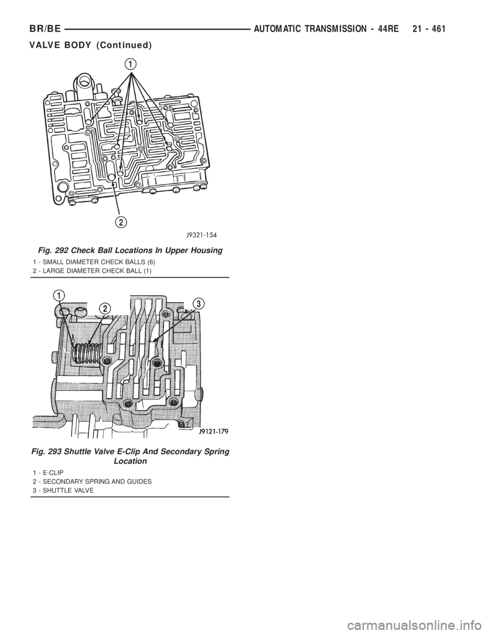
Fig. 292 Check Ball Locations In Upper Housing
1 - SMALL DIAMETER CHECK BALLS (6)
2 - LARGE DIAMETER CHECK BALL (1)
Fig. 293 Shuttle Valve E-Clip And Secondary Spring
Location
1 - E-CLIP
2 - SECONDARY SPRING AND GUIDES
3 - SHUTTLE VALVE
BR/BEAUTOMATIC TRANSMISSION - 44RE 21 - 461
VALVE BODY (Continued)
Page 2097 of 2889
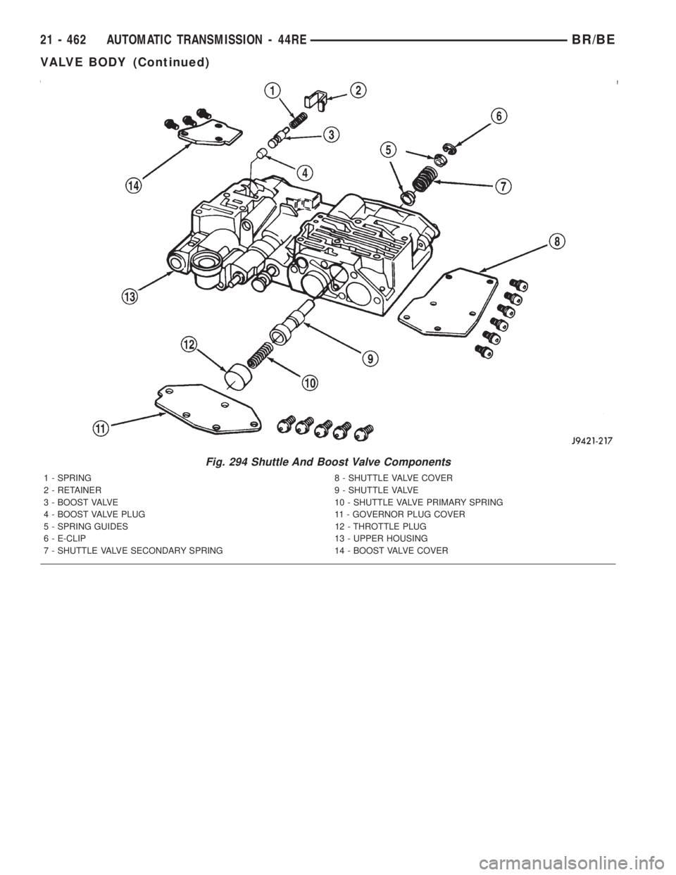
Fig. 294 Shuttle And Boost Valve Components
1 - SPRING 8 - SHUTTLE VALVE COVER
2 - RETAINER 9 - SHUTTLE VALVE
3 - BOOST VALVE 10 - SHUTTLE VALVE PRIMARY SPRING
4 - BOOST VALVE PLUG 11 - GOVERNOR PLUG COVER
5 - SPRING GUIDES 12 - THROTTLE PLUG
6 - E-CLIP 13 - UPPER HOUSING
7 - SHUTTLE VALVE SECONDARY SPRING 14 - BOOST VALVE COVER
21 - 462 AUTOMATIC TRANSMISSION - 44REBR/BE
VALVE BODY (Continued)
Page 2098 of 2889
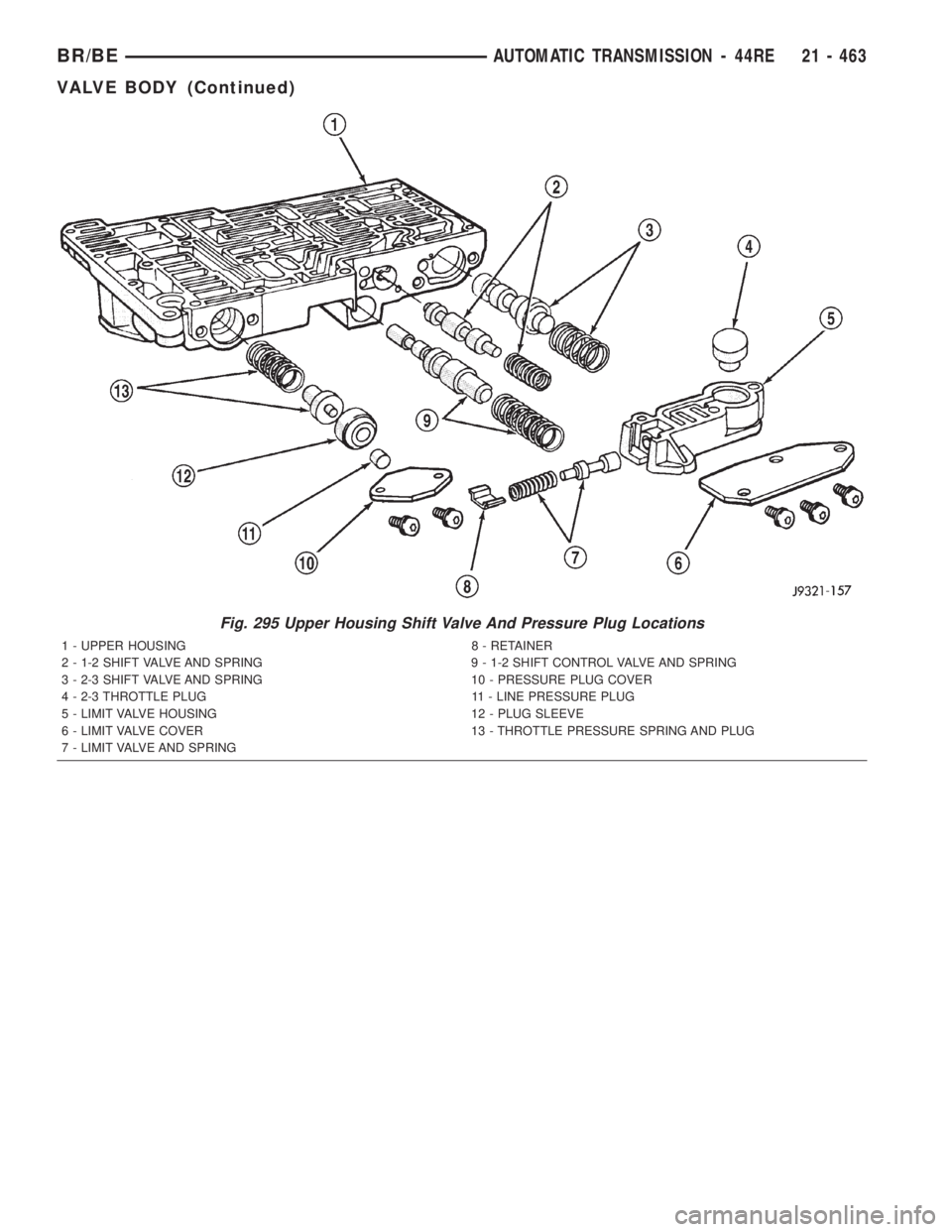
Fig. 295 Upper Housing Shift Valve And Pressure Plug Locations
1 - UPPER HOUSING 8 - RETAINER
2 - 1-2 SHIFT VALVE AND SPRING 9 - 1-2 SHIFT CONTROL VALVE AND SPRING
3 - 2-3 SHIFT VALVE AND SPRING 10 - PRESSURE PLUG COVER
4 - 2-3 THROTTLE PLUG 11 - LINE PRESSURE PLUG
5 - LIMIT VALVE HOUSING 12 - PLUG SLEEVE
6 - LIMIT VALVE COVER 13 - THROTTLE PRESSURE SPRING AND PLUG
7 - LIMIT VALVE AND SPRING
BR/BEAUTOMATIC TRANSMISSION - 44RE 21 - 463
VALVE BODY (Continued)
Page 2099 of 2889
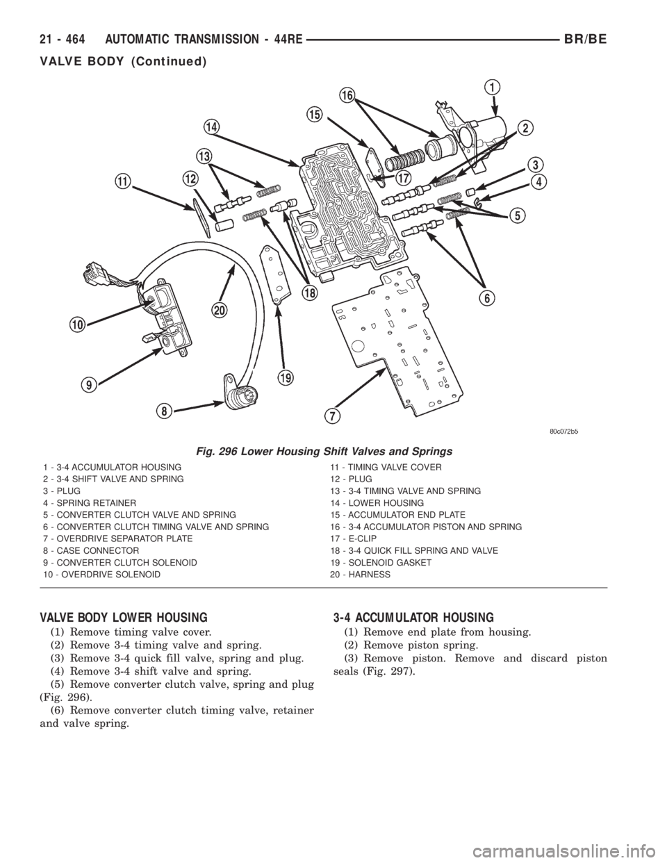
VALVE BODY LOWER HOUSING
(1) Remove timing valve cover.
(2) Remove 3-4 timing valve and spring.
(3) Remove 3-4 quick fill valve, spring and plug.
(4) Remove 3-4 shift valve and spring.
(5) Remove converter clutch valve, spring and plug
(Fig. 296).
(6) Remove converter clutch timing valve, retainer
and valve spring.
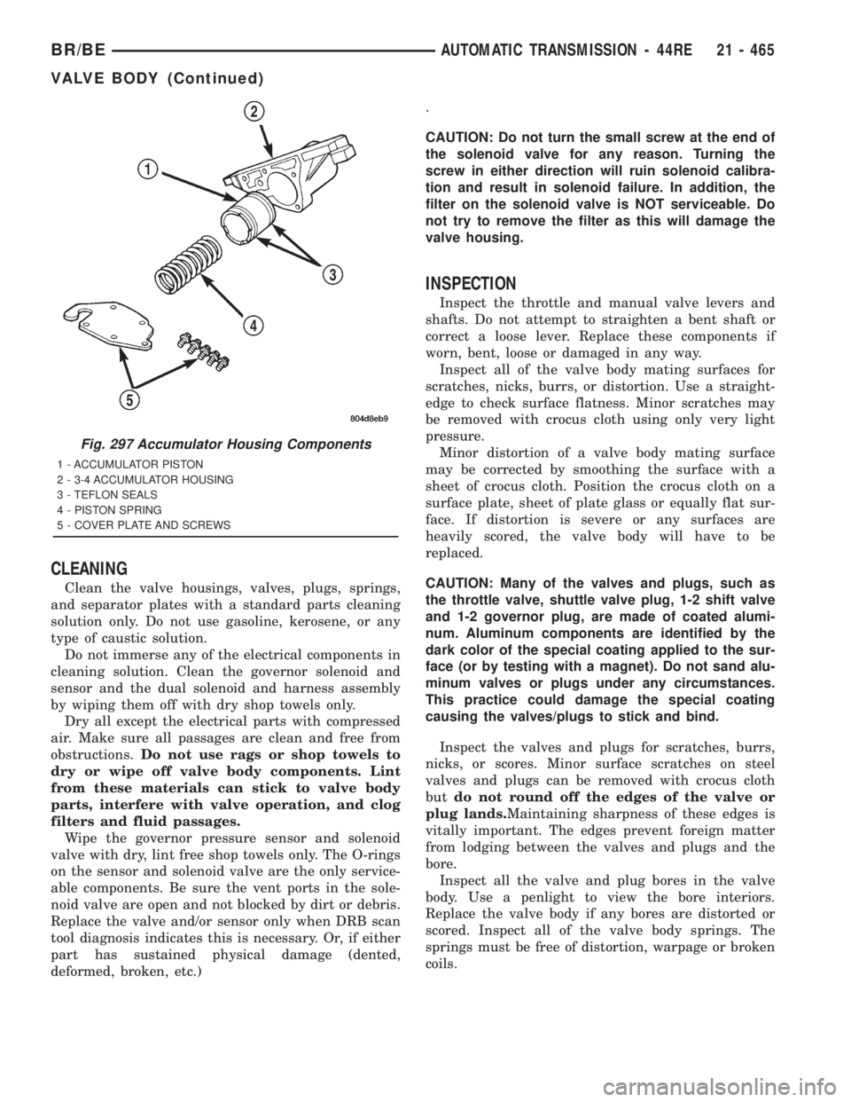
3-4 ACCUMULATOR HOUSING
(1) Remove end plate from housing.
(2) Remove piston spring.
(3) Remove piston. Remove and discard piston
seals (Fig. 297).
Fig. 296 Lower Housing Shift Valves and Springs
1 - 3-4 ACCUMULATOR HOUSING 11 - TIMING VALVE COVER
2 - 3-4 SHIFT VALVE AND SPRING 12 - PLUG
3 - PLUG 13 - 3-4 TIMING VALVE AND SPRING
4 - SPRING RETAINER 14 - LOWER HOUSING
5 - CONVERTER CLUTCH VALVE AND SPRING 15 - ACCUMULATOR END PLATE
6 - CONVERTER CLUTCH TIMING VALVE AND SPRING 16 - 3-4 ACCUMULATOR PISTON AND SPRING
7 - OVERDRIVE SEPARATOR PLATE 17 - E-CLIP
8 - CASE CONNECTOR 18 - 3-4 QUICK FILL SPRING AND VALVE
9 - CONVERTER CLUTCH SOLENOID 19 - SOLENOID GASKET
10 - OVERDRIVE SOLENOID 20 - HARNESS
21 - 464 AUTOMATIC TRANSMISSION - 44REBR/BE
VALVE BODY (Continued)
Page 2100 of 2889
CLEANING
Clean the valve housings, valves, plugs, springs,
and separator plates with a standard parts cleaning
solution only. Do not use gasoline, kerosene, or any
type of caustic solution.
Do not immerse any of the electrical components in
cleaning solution. Clean the governor solenoid and
sensor and the dual solenoid and harness assembly
by wiping them off with dry shop towels only.
Dry all except the electrical parts with compressed
air. Make sure all passages are clean and free from
obstructions.Do not use rags or shop towels to
dry or wipe off valve body components. Lint
from these materials can stick to valve body
parts, interfere with valve operation, and clog
filters and fluid passages.
Wipe the governor pressure sensor and solenoid
valve with dry, lint free shop towels only. The O-rings
on the sensor and solenoid valve are the only service-
able components. Be sure the vent ports in the sole-
noid valve are open and not blocked by dirt or debris.
Replace the valve and/or sensor only when DRB scan
tool diagnosis indicates this is necessary. Or, if either
part has sustained physical damage (dented,
deformed, broken, etc.).
CAUTION: Do not turn the small screw at the end of
the solenoid valve for any reason. Turning the
screw in either direction will ruin solenoid calibra-
tion and result in solenoid failure. In addition, the
filter on the solenoid valve is NOT serviceable. Do
not try to remove the filter as this will damage the
valve housing.
INSPECTION
Inspect the throttle and manual valve levers and
shafts. Do not attempt to straighten a bent shaft or
correct a loose lever. Replace these components if
worn, bent, loose or damaged in any way.
Inspect all of the valve body mating surfaces for
scratches, nicks, burrs, or distortion. Use a straight-
edge to check surface flatness. Minor scratches may
be removed with crocus cloth using only very light
pressure.
Minor distortion of a valve body mating surface
may be corrected by smoothing the surface with a
sheet of crocus cloth. Position the crocus cloth on a
surface plate, sheet of plate glass or equally flat sur-
face. If distortion is severe or any surfaces are
heavily scored, the valve body will have to be
replaced.
CAUTION: Many of the valves and plugs, such as
the throttle valve, shuttle valve plug, 1-2 shift valve
and 1-2 governor plug, are made of coated alumi-
num. Aluminum components are identified by the
dark color of the special coating applied to the sur-
face (or by testing with a magnet). Do not sand alu-
minum valves or plugs under any circumstances.
This practice could damage the special coating
causing the valves/plugs to stick and bind.
Inspect the valves and plugs for scratches, burrs,
nicks, or scores. Minor surface scratches on steel
valves and plugs can be removed with crocus cloth
butdo not round off the edges of the valve or
plug lands.Maintaining sharpness of these edges is
vitally important. The edges prevent foreign matter
from lodging between the valves and plugs and the
bore.
Inspect all the valve and plug bores in the valve
body. Use a penlight to view the bore interiors.
Replace the valve body if any bores are distorted or
scored. Inspect all of the valve body springs. The
springs must be free of distortion, warpage or broken
coils.
Fig. 297 Accumulator Housing Components
1 - ACCUMULATOR PISTON
2 - 3-4 ACCUMULATOR HOUSING
3 - TEFLON SEALS
4 - PISTON SPRING
5 - COVER PLATE AND SCREWS
BR/BEAUTOMATIC TRANSMISSION - 44RE 21 - 465
VALVE BODY (Continued)