DODGE SPRINTER 2007 2.G Owners Manual
Manufacturer: DODGE, Model Year: 2007, Model line: SPRINTER, Model: DODGE SPRINTER 2007 2.GPages: 393, PDF Size: 7.61 MB
Page 301 of 393
300 Practical hintsWhere will I find...?
5
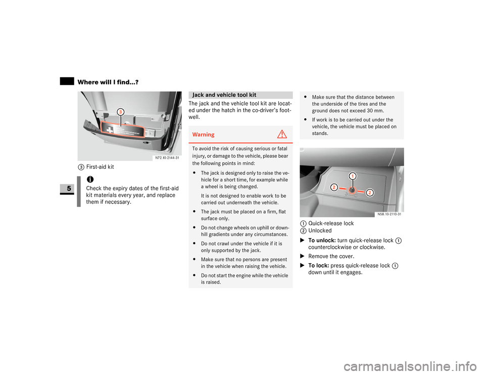
3First-aid kitThe jack and the vehicle tool kit are locat-
ed under the hatch in the co-driver’s foot-
well.
1Quick-release lock
2Unlocked
\1To unlock: turn quick-release lock 1
counterclockwise or clockwise.
\1Remove the cover.
\1To lock: press quick-release lock 1
down until it engages.
iCheck the expiry dates of the first-aid
kit materials every year, and replace
them if necessary.
Jack and vehicle tool kitWarning
G
To avoid the risk of causing serious or fatal
injury, or damage to the vehicle, please bear
the following points in mind:
\4The jack is designed only to raise the ve-
hicle for a short time, for example while
a wheel is being changed.
It is not designed to enable work to be
carried out underneath the vehicle.
\4The jack must be placed on a firm, flat
surface only.
\4Do not change wheels on uphill or down-
hill gradients under any circumstances.
\4Do not crawl under the vehicle if it is
only supported by the jack.
\4Make sure that no persons are present
in the vehicle when raising the vehicle.
\4Do not start the engine while the vehicle
is raised.
\4Make sure that the distance between
the underside of the tires and the
ground does not exceed 30 mm.
\4If work is to be carried out under the
vehicle, the vehicle must be placed on
stands.
Page 302 of 393
301 Practical hints
Where will I find...?
5
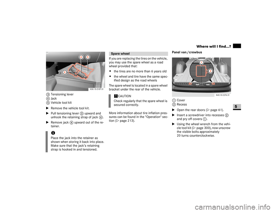
3Tensioning lever
4Jack
5Vehicle tool kit
\1Remove the vehicle tool kit.
\1Pull tensioning lever3 upward and
unhook the retaining strap of jack4.
\1Remove jack4 upward out of the re-
tainer.If you are replacing the tires on the vehicle,
you may use the spare wheel as a road
wheel provided that:
\4the tires are no more than 6 years old
\4the wheel and tire have the same spec-
ified design as the road wheels
The spare wheel is located in a spare wheel
bracket under the rear of the vehicle.
More information about tire inflation pres-
sures can be found in the "Operation" sec-
tion (\2page 213).Panel van / crewbus
1Cover
2Recess
\1Open the rear doors (\2page 61).
\1Insert a screwdriver into recesses2
and pry off covers1.
\1Using the wheel wrench from the vehi-
cle tool kit (\2page 300), now unscrew
the visible bolts approximately
20 turns counterclockwise.
iPlace the jack into the retainer as
shown when storing it back into place.
Make sure that the jack’s retaining
strap is hooked in and tensioned.
Spare wheel!
CAUTION
Check regularly that the spare wheel is
secured correctly.
Page 303 of 393
302 Practical hintsWhere will I find...?
5
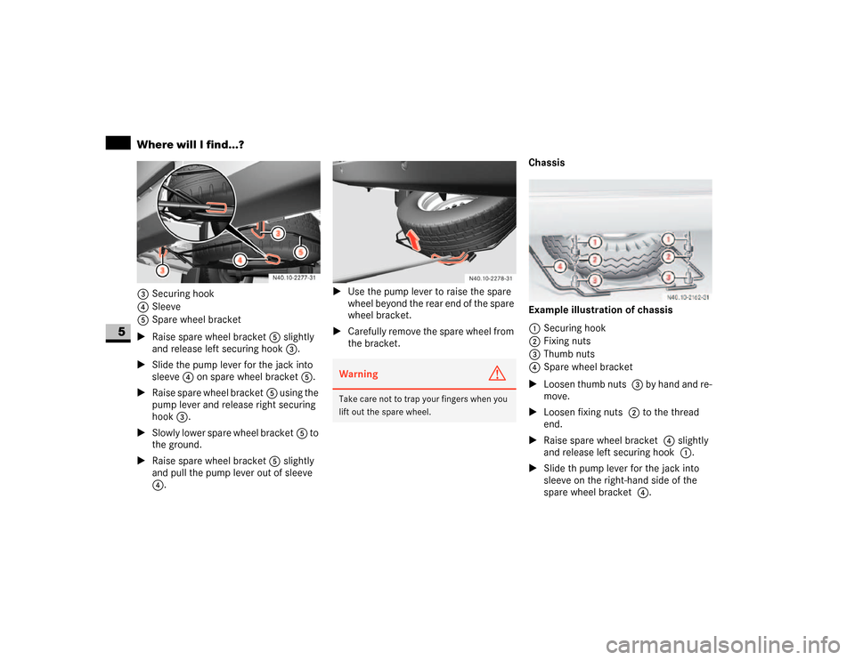
3Securing hook
4Sleeve
5Spare wheel bracket
\1Raise spare wheel bracket5 slightly
and release left securing hook3.
\1Slide the pump lever for the jack into
sleeve4 on spare wheel bracket5.
\1Raise spare wheel bracket5 using the
pump lever and release right securing
hook3.
\1Slowly lower spare wheel bracket5 to
the ground.
\1Raise spare wheel bracket5 slightly
and pull the pump lever out of sleeve
4.\1Use the pump lever to raise the spare
wheel beyond the rear end of the spare
wheel bracket.
\1Carefully remove the spare wheel from
the bracket.Chassis
Example illustration of chassis
1Securing hook
2Fixing nuts
3Thumb nuts
4Spare wheel bracket
\1Loosen thumb nuts 3 by hand and re-
move.
\1Loosen fixing nuts 2 to the thread
end.
\1Raise spare wheel bracket 4 slightly
and release left securing hook 1.
\1Slide th pump lever for the jack into
sleeve on the right-hand side of the
spare wheel bracket 4.
Warning
G
Take care not to trap your fingers when you
lift out the spare wheel.
Page 304 of 393
303 Practical hints
Where will I find...?
5
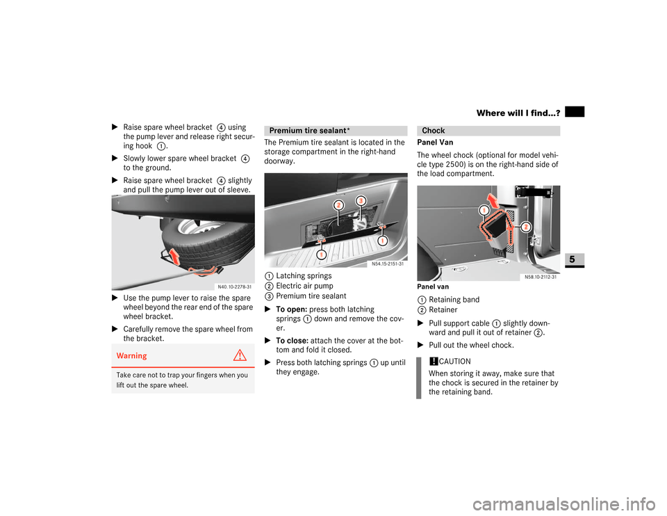
\1Raise spare wheel bracket 4 using
the pump lever and release right secur-
ing hook 1.
\1Slowly lower spare wheel bracket 4
to the ground.
\1Raise spare wheel bracket 4 slightly
and pull the pump lever out of sleeve.
\1Use the pump lever to raise the spare
wheel beyond the rear end of the spare
wheel bracket.
\1Carefully remove the spare wheel from
the bracket.The Premium tire sealant is located in the
storage compartment in the right-hand
doorway.
1Latching springs
2Electric air pump
3Premium tire sealant
\1To open: press both latching
springs1 down and remove the cov-
er.
\1To close: attach the cover at the bot-
tom and fold it closed.
\1Press both latching springs1 up until
they engage.Panel Van
The wheel chock (optional for model vehi-
cle type 2500) is on the right-hand side of
the load compartment.
Panel van1Retaining band
2Retainer
\1Pull support cable 1 slightly down-
ward and pull it out of retainer 2.
\1Pull out the wheel chock.
Warning
G
Take care not to trap your fingers when you
lift out the spare wheel.
Premium tire sealant*
Chock!
CAUTION
When storing it away, make sure that
the chock is secured in the retainer by
the retaining band.
Page 305 of 393
304 Practical hintsWhere will I find...?
5
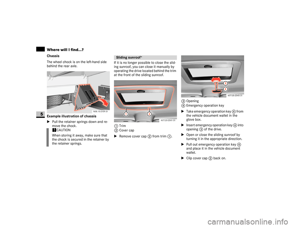
Chassis
The wheel chock is on the left-hand side
behind the rear axle.
Example illustration of chassis
\1Pull the retainer springs down and re-
move the chock.If it is no longer possible to close the slid-
ing sunroof, you can close it manually by
operating the drive located behind the trim
at the front of the sliding sunroof.
1Trim
2Cover cap
\1Remove cover cap2 from trim1.3Opening
4Emergency operation key
\1Take emergency operation key 4 from
the vehicle document wallet in the
glove box.
\1Insert emergency operation key 4 into
opening3 of the drive.
\1Open or close the sliding sunroof by
turning it in the appropriate direction.
\1Pull out emergency operation key 4
and place it in the vehicle document
wallet.
\1Clip cover cap2 back on.
!
CAUTION
When storing it away, make sure that
the chock is secured in the retainer by
the retainer springs.
Sliding sunroof*
N77.20-2041-31
N77.20-2040-31
Page 306 of 393
305 Practical hints
Where will I find...?
5
\1With the ignition switched on
(\2page 67), press and hold the sliding
sunroof switch (\2page 145) forward
or backward for 45 seconds to reset
the electronics.
\1Reset the sliding sunroof
(\2page 146).
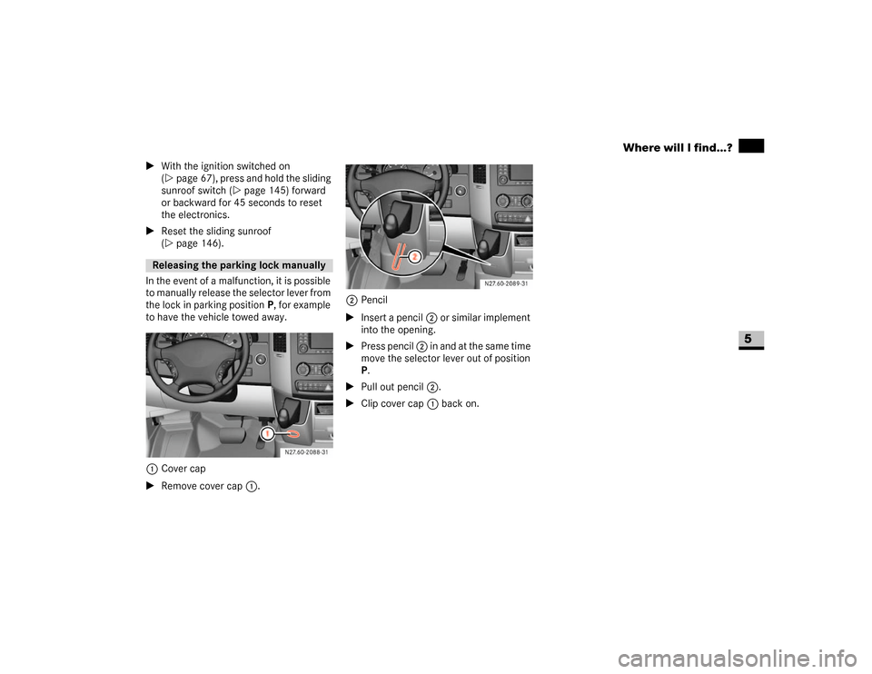
In the event of a malfunction, it is possible
to manually release the selector lever from
the lock in parking positionP, for example
to have the vehicle towed away.
1Cover cap
\1Remove cover cap1.2Pencil
\1Insert a pencil2 or similar implement
into the opening.
\1Press pencil 2 in and at the same time
move the selector lever out of position
P.
\1Pull out pencil 2.
\1Clip cover cap1 back on.Releasing the parking lock manually
N27.60-2088-31
N27.60-2089-31
Page 307 of 393
306 Practical hintsChanging bulbs
5
\3 Changing bulbsBulbs and lights are an important aspect of
vehicle safety. For this reason, make sure
that all bulbs are in working order at all
times.
\4Switch off the lights to avoid a short cir-
cuit.
\4Only touch new bulbs with a clean lint-
free cloth or something similar. Do not
work with wet or greasy fingers.
\4Only fit 12 V bulbs of the same type as
before and of the correct wattage.
\4Have the headlamp setting checked
regularly.\4If the newly installed bulb does not light
up either, visit an authorized Sprinter
Dealer.
\4Have the following LEDs and bulbs
changed at an authorized Sprinter
Dealer:
\4The additional turn signals in the
exterior mirrors
\4The third brake lamp (cargo and
passenger vans only)*
\4The bi-xenon headlamps*
\4The foglamps* Before changing bulbs
Warning
G
Bulbs and bulb holders can become very
hot. For this reason, allow the light to cool
down before changing the bulb.
Keep bulbs out of the reach of children.
Never use a bulb which has been dropped.
Such a bulb may explode and injure you.
H7 bulbs are pressurized and may explode
when changed. You should therefore wear
eye protection and gloves when you are
changing them.
Page 308 of 393
307 Practical hints
Changing bulbs
5
\1Switch off the lighting.
\1Open the hood (\2page 185).
Bi-xenon headlamps*
High-beam headlamps, low-beam head-
lamps
1Catches
2Housing cover
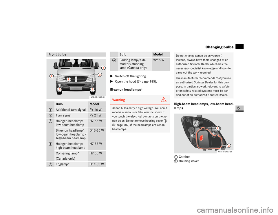
Front bulbs
Bulb
Model
1
Additional turn signal
PY 16 W
2
Turn signal
PY 21 W
3
Halogen headlamp:
low-beam headlamp
H7 55 W
Bi-xenon headlamp*:
low-beam headlamp /
high-beam headlamp
D1S-35 W
4
Halogen headlamp:
high-beam headlamp
H7 55 W
Cornering lamp*
(Canada only)
H7 55 W
5
Foglamp*
H11 55 W
6
Parking lamp/side
marker/standing
lamp (Canada only)
WY 5 W
Warning
G
Xenon bulbs carry a high voltage. You could
receive a serious or fatal electric shock if
you touch the electrical contacts on the xe-
non bulbs. Do not remove housing cover 2
(\2page 307) if the headlamps are xenon
headlamps.
Bulb
Model
Do not change xenon bulbs yourself.
Instead, always have them changed at an
authorized Sprinter Dealer which has the
necessary specialist knowledge and tools to
carry out the work required.
The manufacturer recommends that you use
an authorized Sprinter Dealer for this pur-
pose. In particular, work relevant to safety
or on safety-related systems must be car-
ried out at an authorized Sprinter Dealer.
Page 309 of 393
308 Practical hintsChanging bulbs
5
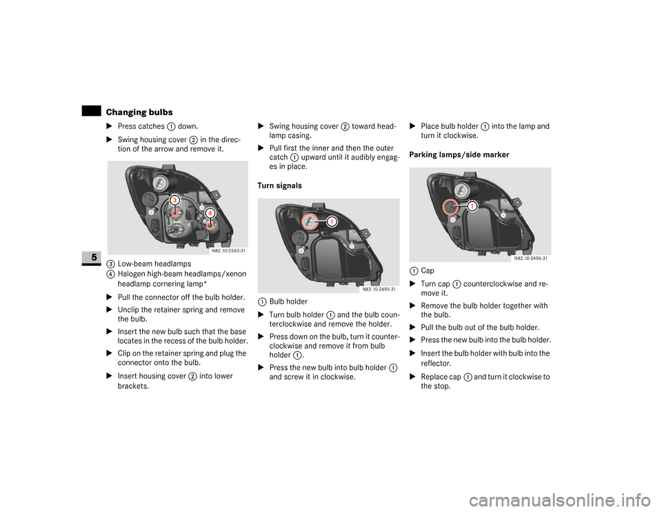
\1Press catches1 down.
\1Swing housing cover2 in the direc-
tion of the arrow and remove it.
3Low-beam headlamps
4Halogen high-beam headlamps/xenon
headlamp cornering lamp*
\1Pull the connector off the bulb holder.
\1Unclip the retainer spring and remove
the bulb.
\1Insert the new bulb such that the base
locates in the recess of the bulb holder.
\1Clip on the retainer spring and plug the
connector onto the bulb.
\1Insert housing cover 2 into lower
brackets.\1Swing housing cover 2 toward head-
lamp casing.
\1Pull first the inner and then the outer
catch1 upward until it audibly engag-
es in place.
Turn signals
1Bulb holder
\1Turn bulb holder1 and the bulb coun-
terclockwise and remove the holder.
\1Press down on the bulb, turn it counter-
clockwise and remove it from bulb
holder1.
\1Press the new bulb into bulb holder1
and screw it in clockwise.\1Place bulb holder1 into the lamp and
turn it clockwise.
Parking lamps/side marker
1Cap
\1Turn cap1 counterclockwise and re-
move it.
\1Remove the bulb holder together with
the bulb.
\1Pull the bulb out of the bulb holder.
\1Press the new bulb into the bulb holder.
\1Insert the bulb holder with bulb into the
reflector.
\1Replace cap1 and turn it clockwise to
the stop.
Page 310 of 393
309 Practical hints
Changing bulbs
5
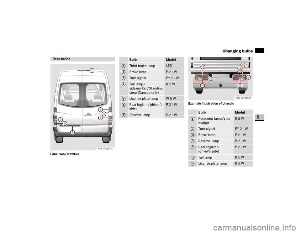
Panel van/crewbusExample illustration of chassisRear bulbs
N82.10-2529-31
Bulb
Model
1
Third brake lamp
LED
2
Brake lamp
P21W
3
Turn signal
PY 21 W
4
Tail lamp /
side marker/Standing
lamp (Canada only)
R5W
5
License plate lamp
W5W
6
Rear foglamp (driver’s
side)
P 21 W
7
Reverse lamp
P 21 W
Bulb
Model
8
Perimeter lamp/side
marker
R5W
9
Turn signal
PY 21 W
a
Brake lamp
P21W
b
Reverse lamp
P21W
c
Rear foglamp
(driver’s side)
P 21 W
d
Tail lamp
R5W
e
License plate lamp
R5W