DODGE TRUCK 1993 Service Repair Manual
Manufacturer: DODGE, Model Year: 1993, Model line: TRUCK, Model: DODGE TRUCK 1993Pages: 1502, PDF Size: 80.97 MB
Page 181 of 1502
3
- 54
REAR SUSPENSION
AID
AXLE
•
CLEANING AND INSPECTION
(1) Clean all components in cleaning solvent. Dry
components with compressed air. (2) Inspect clutch pack plates for wear, scoring or
damage. Replace both clutch packs if any one compo
nent in either pack is damaged. (3) Inspect side and pinion gears. Replace any gear
that is worn, cracked, chipped or damaged. (4) Inspect differential case and pinion shaft. Re
place if worn or damaged.
ASSEMBLY
(1) The clutch discs are replaceable as complete
sets only. If one clutch disc pack is damaged,
both packs must be replaced. Lubricate each com
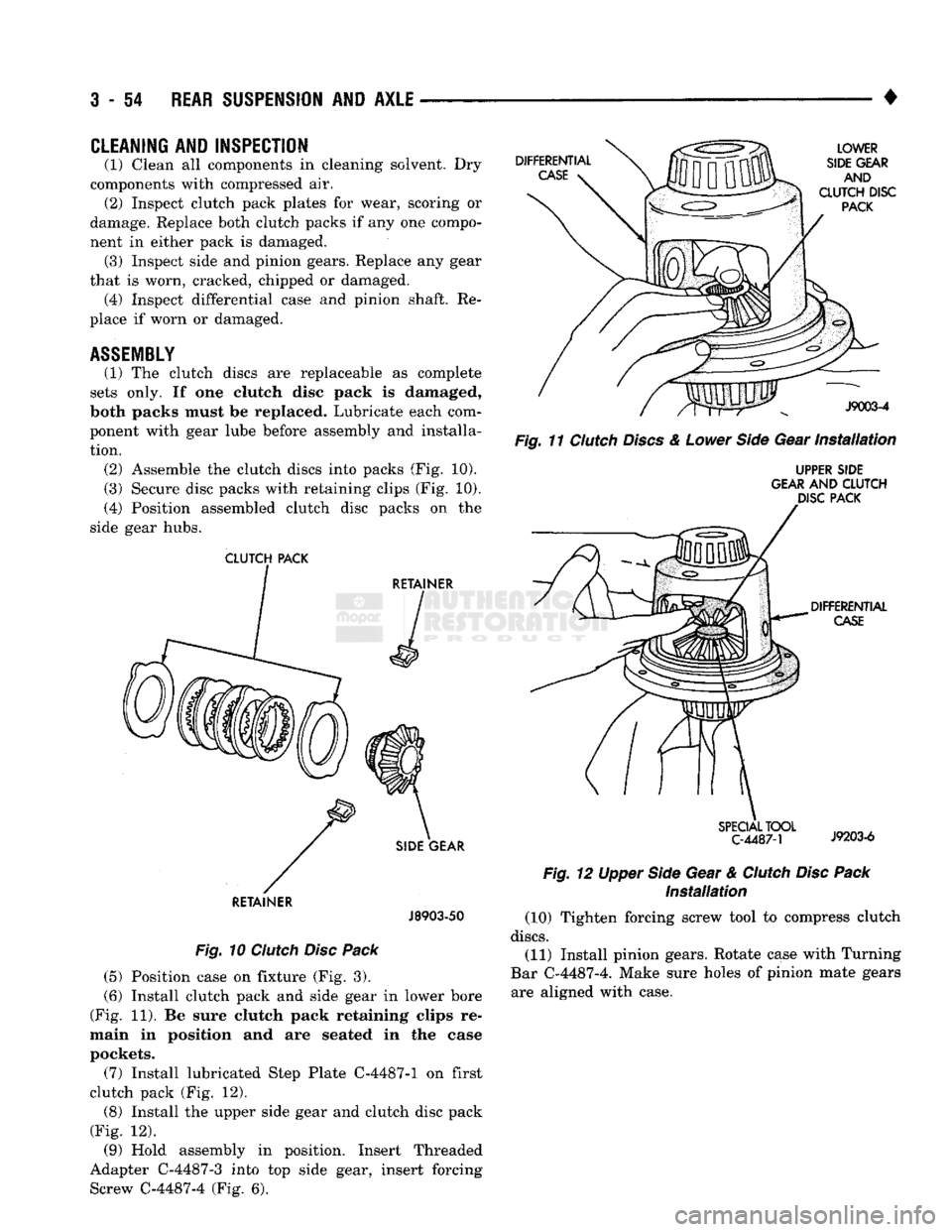
ponent with gear lube before assembly and installa tion. (2) Assemble the clutch discs into packs (Fig. 10).
(3) Secure disc packs with retaining clips (Fig. 10).
(4) Position assembled clutch disc packs on the
side gear hubs.
CLUTCH
PACK
RETAINER
J8903-50
Fig.
10
Clutch
Disc
Pack
(5) Position case on fixture (Fig. 3).
(6) Install clutch pack and side gear in lower bore
(Fig. 11). Be sure clutch pack retaining clips re
main in position and are seated in the case
pockets.
(7) Install lubricated Step Plate C-4487-1 on first
clutch pack (Fig. 12). (8) Install the upper side gear and clutch disc pack
(Fig. 12).
(9) Hold assembly in position. Insert Threaded
Adapter C-4487-3 into top side gear, insert forcing Screw C-4487-4 (Fig. 6).
Fig.
11
Clutch
Discs
&
Lower
Side
Gear
Installation
UPPER SIDE
GEAR AND
CLUTCH
DISC PACK
Installation
(10) Tighten forcing screw tool to compress clutch
discs.
(11) Install pinion gears. Rotate case with Turning
Bar C-4487-4. Make sure holes of pinion mate gears are aligned with case.
Page 182 of 1502
•
REAR
SUSPENSION
AND
AXLE
3 - 55
(12) Tighten forcing screw
to
compress
the
conned
plates.
Lubricate
and
install pinion gear thrust washers with
a
small screw driver.
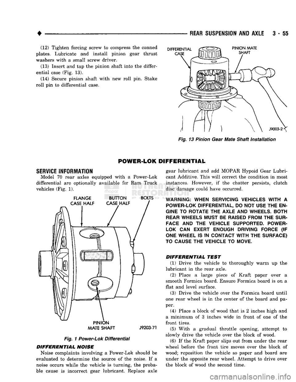
(13) Insert and tap
the
pinion shaft into the differ
ential case (Fig.
13).
(14) Secure pinion shaft with
new
roll pin. Stake
roll
pin
to
differential case.
Fig.
13
Pinion
Gear
Mate
Shaft
installation
POWER-LOK
DIFFERENTIAL
SERVICE
INFORMATION Model
70
rear axles equipped with
a
Power-Lok
differential
are
optionally available
for
Ram
Truck
vehicles (Fig.
1).
FLANGE
BUTTON
BOLTS
PINION
AAATE
SHAFT
J9203-71
Fig.
1
Power-Lok
Differential
DIFFERENTIAL
NOISE
Noise complaints involving
a
Power-Lok should
be
evaluated
to
determine
the
source
of
the noise.
If a
noise occurs while
the
vehicle
is
turning,
the
proba
ble cause
is
incorrect gear lubricant. Replace axle gear lubricant
and add
MOPAR Hypoid Gear Lubri
cant Additive. This will correct the condition
in
most
instances. However,
if the
chatter persists, clutch
disc damage could have occurred.
WARNING:
WHEN SERVICING VEHICLES
WITH
A
POWER-LOK
DIFFERENTIAL, DO NOT USE THE EN
GINE
TO
ROTATE THE AXLE AND
WHEELS.
BOTH
REAR
WHEELS MUST BE
RAISED
FROM THE
SUR
FACE
AND
THE
VEHICLE SUPPORTED. POWER-
LOK
CAN
EXERT ENOUGH DRIVING FORCE
(IF
ONE
WHEEL IS
IN
CONTACT
WITH
THE SURFACE)
TO
CAUSE
THE VEHICLE TO MOVE.
DIFFERENTIAL
TEST
(1) Drive
the
vehicle
to
thoroughly warm
up the
lubricant
in
the
rear axle.
(2) Place
a
large piece
of
Kraft paper over
a
smooth Formica board. Ensure Formica board
is on a
flat and level surface.
(3) Drive
the
vehicle over
the
Formica board until
one rear wheel
is in the
center
of
the board
and
pa
per. (4) Place
a
block
of
wood that
is 2
inches high
and
a minimum
of 3
inches wide
in
front
of
one
of
the
front tires.
(5) With
a
gradual throttle opening, attempt
to
slowly drive
the
vehicle over
the
block
of
wood.
(6)
If
the Kraft paper slips out from under the rear
wheel before
the
front tire moves over
the
block
of
wood; reposition
the
vehicle
so
paper
and
board
are
under
the
opposite rear wheel. Attempt
to
drive over
the block
of
wood
the
second time.
Page 183 of 1502
3
- 56
REAR SUSPENSION
AND
AXLE
CLUTCH
PLATES
J9203-72
BUTTON
HALF
FLANGE
HALF
Fig.
2
Case
Marked
(7)
If the front wheel moves over the block of wood,
the axle can be considered to be functioning normally.
LUBRICANTS
The lubricant recommended for Power-Lok differ
ential is API grade GL 5. A container of Trac-Lok
Lubricant (friction modifier) should be added after
service. Refer to Group 0, Lubrication and Maintenance for
additional information.
FLANGE
HALF
CLUTCH
RING
J9203-73
Fig.
3
Cover
Half
Removal
DISASSEMBLY
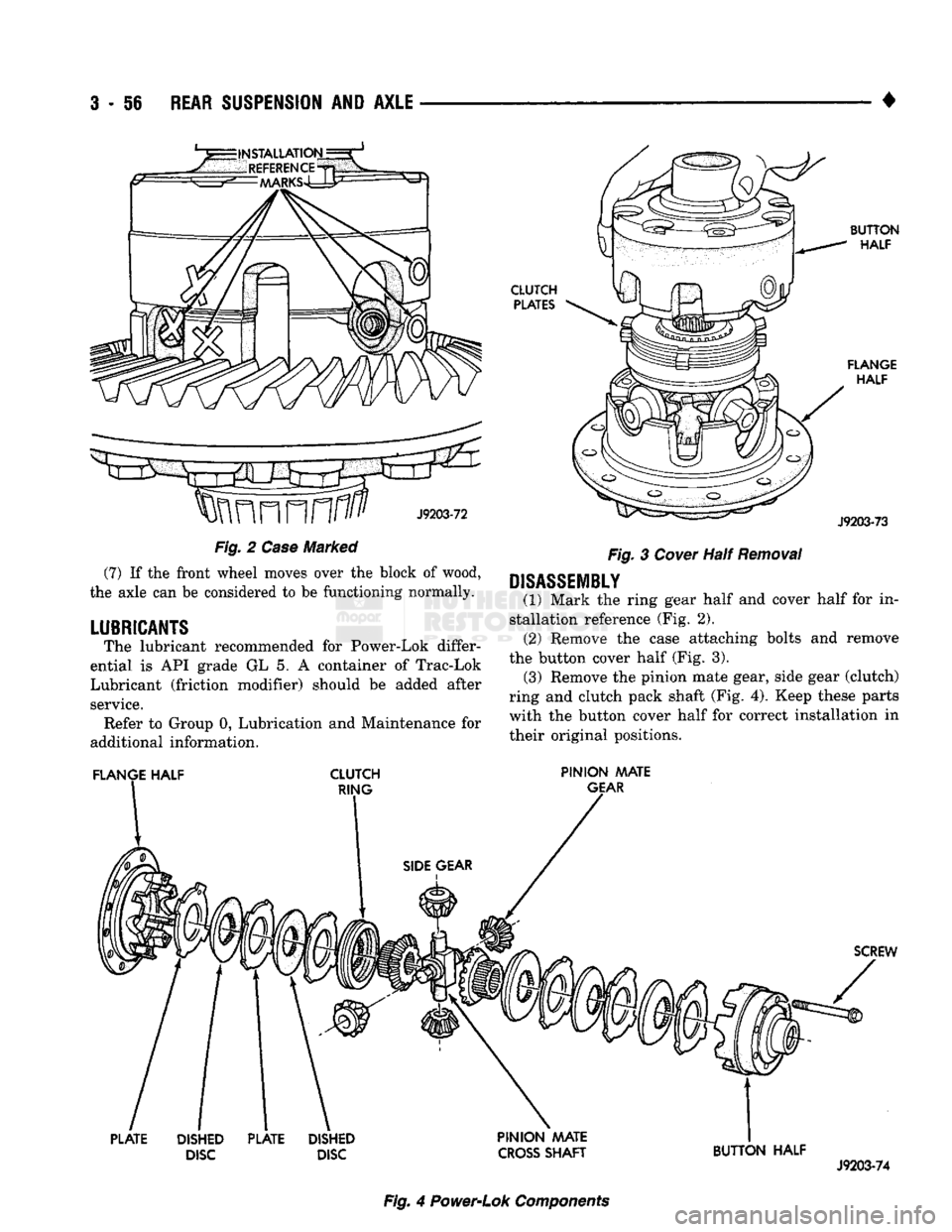
(1) Mark the ring gear half and cover half for in
stallation reference (Fig. 2). (2) Remove the case attaching bolts and remove
the button cover half (Fig. 3). (3) Remove the pinion mate gear, side gear (clutch)
ring and clutch pack shaft (Fig. 4). Keep these parts with the button cover half for correct installation in
their original positions.
PINION MATE
GEAR
SCREW
PLATE
DISHED
DISC
PLATE
DISHED
DISC PINION AAATE
CROSS
SHAFT
BUTTON HALF
J9203-74
Fig.
4
Power-Lok
Components
Page 184 of 1502
•
REAR SUSPENSION
AND
AXLE
3 - 57 (4) Remove the same parts listed above from the
ring gear flange half of the case. (Fig. 4). Keep these
parts with the flange cover half for correct installa tion in their original positions.
CLEANING AND INSPECTION
(1) Clean all components (Fig. 4) in cleaning sol
vent. Dry components with compressed air. (2) Inspect clutch pack plates for wear, scoring or
damage. Replace both clutch packs if any one compo
nent in either pack is damaged. (3) Inspect side and pinion gears. Replace any gear
that is worn, cracked, chipped or damaged. (4) Inspect differential case and pinion shaft. Re
place if worn or damaged.
ASSEMBLY
(1) The clutch discs are replaceable as complete
sets only. If one clutch disc pack is damaged,
both packs must be replaced. Lubricate each com
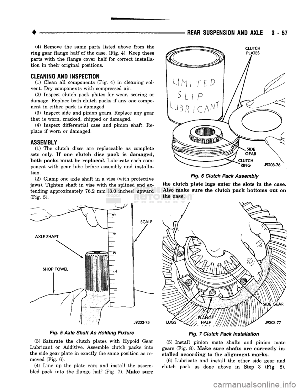
ponent with gear lube before assembly and installa tion. (2) Clamp one axle shaft in a vise (with protective
jaws).
Tighten shaft in vise with the splined end ex tending approximately 76.2 mm (3.0 inches) upward (Fig. 5).
Fig.
5 Axle Shaft As
Holding
Fixture
(3) Saturate the clutch plates with Hypoid Gear
Lubricant or Additive. Assemble clutch packs into
the side gear plate in exactly the same position as re moved (Fig. 6).
(4) Line up the plate ears and install the assem
bled pack into the flange half (Fig. 7). Make sure
Fig.
6
Clutch
Pack
Assembly
the clutch plate lugs enter the slots in the case.
Also make sure the clutch pack bottoms out on
the case.
Fig.
7
Clutch
Pack
Installation
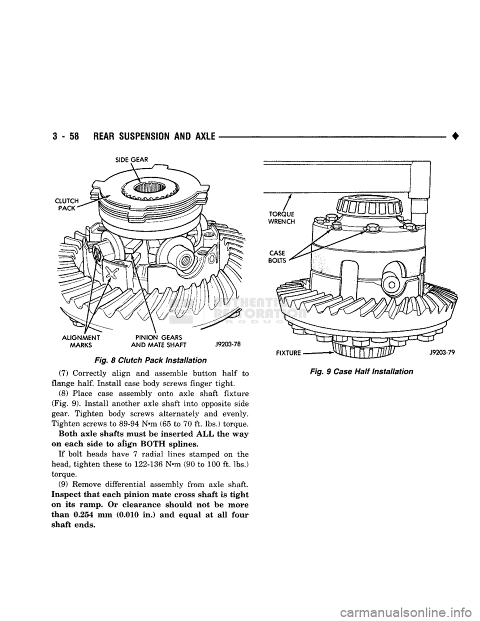
(5) Install pinion mate shafts and pinion mate
gears (Fig. 8). Make sure shafts are correctly in stalled according to the alignment marks.
(6) Lubricate and install the other side gear and
clutch pack as done above in Step 3 (Fig. 8).
Page 185 of 1502
3
- 58
REAR SUSPENSION
AND
AXLE
•
SIDE
GEAR
ALIGNMENT PINION
GEARS MARKS
AND
MATE SHAFT
J9203-78
Fig.
8
Clutch
Pack
Installation
(7) Correctly align and assemble button half to
flange
half.
Install case body screws finger tight.
(8) Place case assembly onto axle shaft fixture
(Fig. 9). Install another axle shaft into opposite side
gear. Tighten body screws alternately and evenly.
Tighten screws to 89-94 N«m (65 to 70 ft. lbs.) torque.
Both axle shafts must be inserted ALL the way
on each side to align BOTH splines.
If bolt heads have 7 radial lines stamped on the
head, tighten these to 122-136 N-m (90 to 100 ft. lbs.)
torque.
(9) Remove differential assembly from axle shaft.
Inspect that each pinion mate cross shaft is tight
on its ramp. Or clearance should not be more
than 0.254 mm (0.010 in.) and equal at all four shaft ends.
Fig.
9
Case
Half
Installation
Page 186 of 1502
REAR
SUSPENSION
AND
AXLE
3 - 59
TORQUE
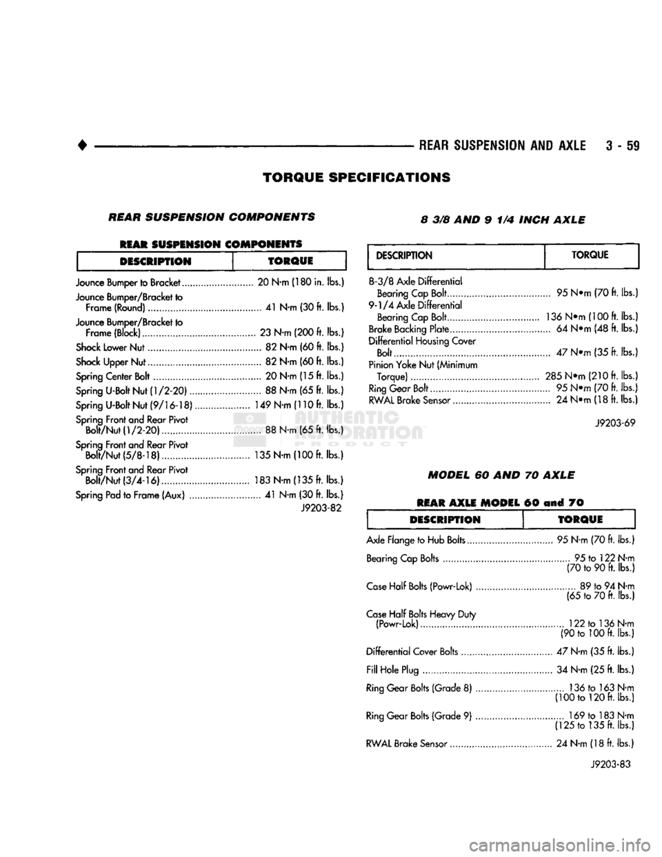
SPECIFICATIONS
REAR
SUSPENSION
COMPONENTS 8 3/8 AND 9 1/4 INCH
AXLE
REAR
SUSPENSION
COMPONENTS
DESCRIPTION
TORQUE
Jounce Bumper to Bracket 20 N-m (180 in. lbs.)
Jounce Bumper/Bracket to Frame (Round) 41 N-m (30 ft. lbs.)
Jounce Bumper/Bracket to Frame (Block)......... 23 N-m (200 ft. lbs.)
Shock
Lower Nut 82 N-m (60 ft. lbs.)
Shock
Upper Nut 82 N-m (60 ft. lbs.)
Spring
Center Bolt 20 N-m (15 ft. lbs.)
Spring
U-Bolt Nut
(1/2-20)
88 N-m (65 ft. lbs.)
Spring
U-Bolt Nut
(9/16-18)
149 N-m (110 ft. lbs.)
Spring
Front and Rear Pivot Bolt/Nut
(1/2-20)
88 N-m (65 ft. lbs.)
Spring
Front and Rear Pivot Bolt/Nut(5/8-18).... 135 N-m
(100ft.
lbs.)
Spring
Front and Rear Pivot Bolt/Nut
(3/4-16)
183 N-m (135 ft. lbs.)
Spring
Pad to Frame (Aux) 41 N-m (30 ft. lbs.)
J9203-82
DESCRIPTION
TORQUE
8-3/8 Axle
Differential
Bearing Cap Bolt
9-1/4 Axle
Differential
Bearing Cap Bolt
Brake
Backing
Plate ,
Differential
Housing
Cover
Bolt
Pinion Yoke Nut (Minimum Torque)
Ring
Gear Bolt...
RWAL
Brake
Sensor
95 N*m (70 ft. lbs.)
136
N*m(100
ft. lbs.)
... 64 N*m (48 ft. lbs.)
47 N*m (35 ft. lbs.;
285Ntti
(210 ft. lbs.)
... 95 N*m (70 ft. lbs.) ... 24 N*m (18 ft. lbs.)
J9203-69
MODEL
60 AND 70
AXLE
REAR
AXLE
MODEL
60 and 70
DESCRIPTION
TORQUE
Axle Flange to Hub Bolts. Bearing Cap Bolts 95 N-m (70 ft. lbs.)
... 95 to 122 N-m (70 to 90 ft. lbs.)
Case
Half
Bolts
(Powr-Lok) ..
Case
Half
Bolts
Heavy Duty (Powr-Lok)
Differential
Cover Bolts
Fill
Hole Plug
Ring
Gear
Bolts
(Grade 8)
Ring
Gear
Bolts
(Grade 9)
RWAL
Brake
Sensor
89 to 94 N-m
(65 to 70 ft. lbs.)
122 to 136 N-m
(90 to 100 ft. lbs.)
47 N-m (35 ft. lbs.) 34 N-m (25 ft. lbs.) 136 to 163 N-m
(100 to 120 ft. lbs.) 169 to 183 N-m
(125 to 135 ft. lbs.)
24 N-m (18 ft. lbs.)
J9203-83
Page 187 of 1502

Page 188 of 1502
•
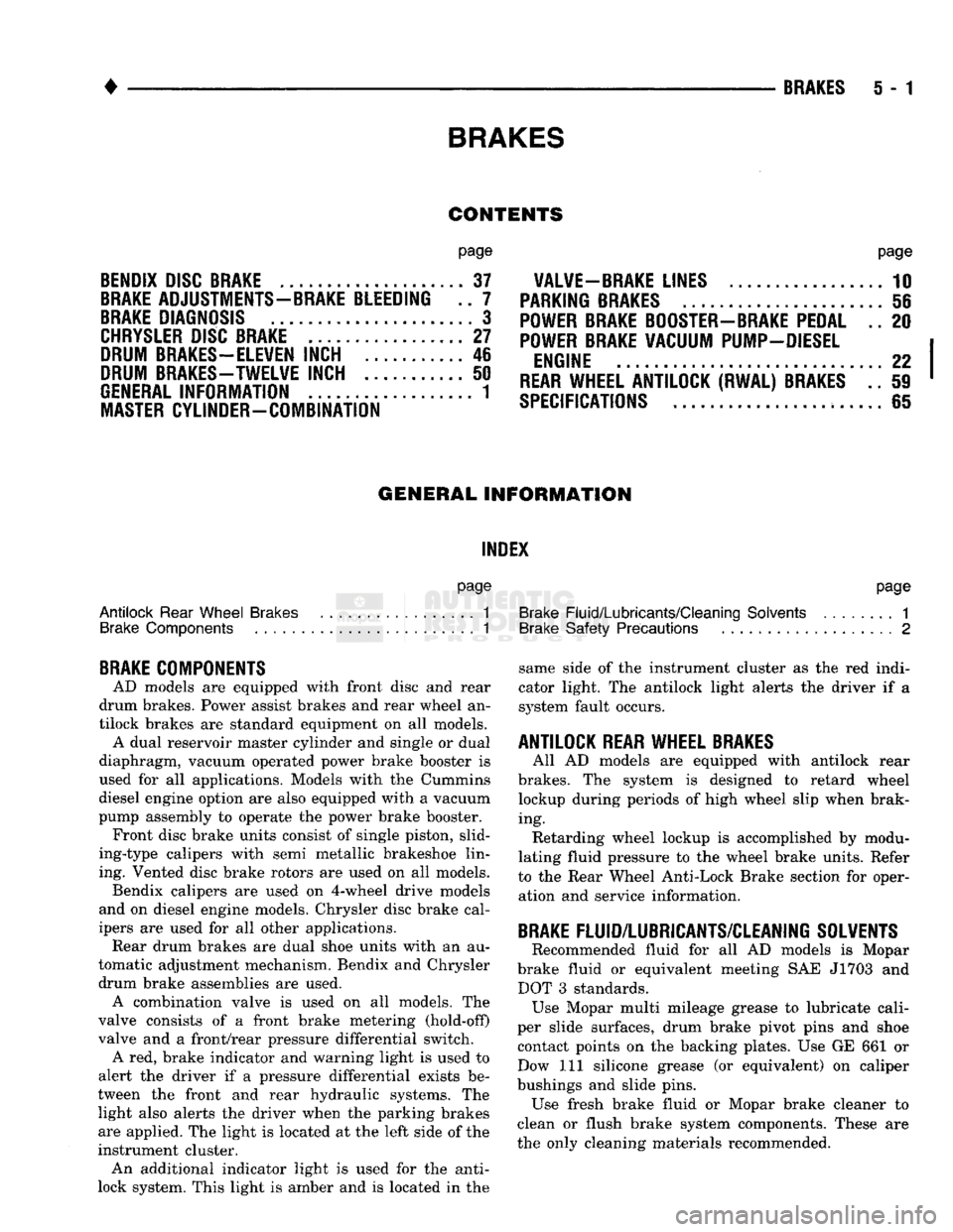
BRAKES
BRAKES
5 - 1
CONTENTS
page
BENDIX
DISC
BRAKE
37
BRAKE
ADJUSTMENTS-BRAKE BLEEDING .. 7
BRAKE
DIAGNOSIS
3
CHRYSLER
DISC
BRAKE
27
DRUM
BRAKES-ELEVEN
INCH 46
DRUM
BRAKES-TWELVE
INCH 50
GENERAL
INFORMATION 1
MASTER
CYLINDER-COMBINATION
page
VALVE-BRAKE
LINES 10
PARKING
BRAKES
56
POWER
BRAKE
BOOSTER-BRAKE
PEDAL .. 20
POWER
BRAKE
VACUUM PUMP-DIESEL
ENGINE
...22
REAR
WHEEL ANTILOCK (RWAL)
BRAKES
.. 59
SPECIFICATIONS
65
GENERAL INFORMATION
INDEX
page
Antilock
Rear
Wheel
Brakes
1
Brake
Components 1
BRAKE
COMPONENTS
AD models are equipped with front disc and rear
drum brakes. Power assist brakes and rear wheel an
tilock brakes are standard equipment on all models. A dual reservoir master cylinder and single or dual
diaphragm, vacuum operated power brake booster is
used for all applications. Models with the Cummins
diesel engine option are also equipped with a vacuum
pump assembly to operate the power brake booster. Front disc brake units consist of single piston, slid-
ing-type calipers with semi metallic brakeshoe lin ing. Vented disc brake rotors are used on all models. Bendix calipers are used on 4-wheel drive models
and on diesel engine models. Chrysler disc brake cal
ipers are used for all other applications. Rear drum brakes are dual shoe units with an au
tomatic adjustment mechanism. Bendix and Chrysler drum brake assemblies are used. A combination valve is used on all models. The
valve consists of a front brake metering (hold-off)
valve and a front/rear pressure differential switch. A red, brake indicator and warning light is used to
alert the driver if a pressure differential exists be
tween the front and rear hydraulic systems. The light also alerts the driver when the parking brakes
are applied. The light is located at the left side of the
instrument cluster. An additional indicator light is used for the anti-
lock system. This light is amber and is located in the
page
Brake
Fluid/Lubricants/Cleaning
Solvents
1
Brake
Safety Precautions 2
same side of the instrument cluster as the red indi
cator light. The antilock light alerts the driver if a system fault occurs.
ANTILOCK
REAR
WHEEL
BRAKES
All AD models are equipped with antilock rear
brakes. The system is designed to retard wheel lockup during periods of high wheel slip when brak
ing. Retarding wheel lockup is accomplished by modu
lating fluid pressure to the wheel brake units. Refer
to the Rear Wheel Anti-Lock Brake section for oper ation and service information.
BRAKE
FLUID/LUBRICANTS/CLEANING SOLVENTS Recommended fluid for all AD models is Mopar
brake fluid or equivalent meeting SAE J1703 and DOT 3 standards. Use Mopar multi mileage grease to lubricate cali
per slide surfaces, drum brake pivot pins and shoe contact points on the backing plates. Use GE 661 or
Dow 111 silicone grease (or equivalent) on caliper
bushings and slide pins. Use fresh brake fluid or Mopar brake cleaner to
clean or flush brake system components. These are
the only cleaning materials recommended.
Page 189 of 1502
5 - 2 BRAKES
• CAUTION:
Never
use gasoline,
kerosene,
alcohol,
motor
oil, transmission
fluid,
or any
fluid
containing
mineral
oil to
clean
the system
components.
These
fluids
damage
rubber
cups and seals. If system
contamination
is suspected,
check
the
fluid
for
dirt,
discoloration,
or
separation
into
distinct
layers.
Drain
and
flush
the system
with
new
brake
fluid
if
contamination
is suspected.
BRAKE
SAFETY PRECAUTIONS WARNING: DUST AND DIRT ON BRAKE PARTS
THAT
ACCUMULATES DURING NORMAL USE MAY CONTAIN ASBESTOS FIBERS. BREATHING
EXCES
SIVE
CONCENTRATIONS OF ASBESTOS FIBERS
CAN
CAUSE SERIOUS BODILY HARM. EXERCISE
CARE
WHEN SERVICING BRAKE COMPONENTS.
DO NOT CLEAN BRAKE COMPONENTS
WITH
COM
PRESSED
AIR OR BY DRY BRUSHING. USE A VAC UUM CLEANER SPECIFICALLY DESIGNED FOR
REMOVING BRAKE DUST
THAT
MAY ASBESTOS
FIBERS.
IF A SUITABLE VACUUM CLEANER IS NOT
AVAILABLE,
CLEANING SHOULD BE DONE USING
A
WATER DAMPENED CLOTH. DO NOT CREATE DUST BY SANDING, GRINDING, OR SHAVING
BRAKE
LININGS UNLESS PROPERLY VENTED
EQUIPMENT IS USED. DISPOSE OF ALL DUST AND
DIRT
THAT
MAY CONTAIN ASBESTOS FIBERS IN
SEALED
BAGS OR CONTAINERS. THIS WILL MINI MIZE EXPOSURE TO YOURSELF AND OTHERS.
FOLLOW ALL RECOMMENDED PRACTICES PRE
SCRIBED
BY THE OCCUPATIONAL SAFETY AND HEALTH ADMINISTRATION AND THE ENVIRON
MENTAL PROTECTION AGENCY FOR THE HAN
DLING, PROCESSING, AND DISPOSITION OF DUST
OR DIRT WHICH MAY CONTAIN ASBESTOS FI
BERS.
Page 190 of 1502
•
BRAKES
i - 3 BRAKE DIAGNOSIS
INDEX
page
Brake
Warning Lights
3
Diagnosing
Brake Problems .................
4
Diagnosis
Procedures
3
Low
Vacuum
Switch—Diesel
Models
3
page
Master
Cylinder/Power Booster Test
5
Power
Booster
Check
Valve Test .............
6
Power
Booster
Vacuum
Test .................
6
Testing Diesel
Engine
Vacuum
Pump
Output
.... 6
DIAGNOSIS
PROCEDURES
Brake diagnosis involves determining
if the
prob
lem
is
related
to a
mechanical, hydraulic
or
vacuum
operated component.
A
preliminary check, road test
ing
and
component inspection
can all be
used
to de
termine
a
problem cause. Road testing will either verify proper brake opera
tion
or
confirm
the
existence
of a
problem. Compo nent inspection will,
in
most cases, identify
the
actual part causing
a
problem. The first diagnosis step
is the
preliminary check. This
involves inspecting fluid level, parking brake action,
wheel
and
tire condition, checking
for
obvious leaks
or
component damage
and
testing brake pedal response. A road test will confirm
the
existence
of a
problem.
Final diagnosis procedure involves road test analysis and
a
visual inspection
of
brake components.
BRAKE
WARNING LIGHTS
The
red
brake warning light
is
connected
to the
parking brake switch
and to the
pressure differential switch
in the
combination valve. The
red
light will illuminate when
the
parking
brakes
are
applied
or
when
a
fluid pressure drop
oc
curs
in the
front
or
rear brake circuit.
The
light will
also illuminate
for
approximately
2-4
seconds
at en
gine start
up.
This
is a
self test feature designed
to
check bulb
and
circuit operation each time
the en
gine
is
started. The amber antilock light
is
connected
to the
anti-
lock rear brake hydraulic valve.
The
light will illu
minate
if a
fault occurs within
the
antilock system.
LOW VACUUM SWITCH-DIESEL MODELS
On diesel models,
the red
brake warning light
is
also
used
to
alert
the
driver
of a low
brake booster vacuum
condition.
The
warning light
is in
circuit with
a
vacuum
warning switch mounted
on the
driver side fender
panel.
The
vacuum side
of the
switch
is
connected
to the
power brake booster.
The
electrical side
of the
switch
is
connected
to the
brake warning light. The
low
vacuum switch monitors booster vacuum
level whenever
the
engine
is
running.
If
booster vac
uum falls below
8.5
inches vacuum
for a
minimum
of
10 seconds,
the
switch completes
the
circuit
to the
warning light causing
it to
illuminate.
The
warning light
is
designed
to
differentiate between
a low
vac
uum condition
and a
hydraulic circuit fault.
PRELIMINARY
BRAKE CHECK
(1) Check condition
of
tires
and
wheels. Damaged
wheels
and
worn, damaged,
or
underinflated tires
can
cause pull, shudder, tramp,
and a
condition similar
to
grab.
(2)
If
complaint
was
based
on
noise when braking,
check suspension components. Jounce front
and
rear
of
vehicle
and
listen
for
noise that might
be
caused
by
loose, worn
or
damaged suspension
or
steering compo
nents.
(3) Inspect brake fluid level
and
condition. Note
that
the
front disc brake reservoir fluid level will drop
in
proportion
to
normal lining wear. Also note
that brake fluid tends
to
darken over time. This
is normal
and
should
not be
mistaken
for
con
tamination.
If the
fluid
is
still clear
and
free
of
foreign material,
it is OK.
(a)
If
fluid level
is
abnormally
low,
look
for
evi
dence
of
leaks
at
calipers, wheel cylinders, brake-
lines
and
master cylinder.
(b)
If
fluid appears contaminated, drain
out a
sample.
If
fluid
is
separated into layers,
or
obvi
ously contains
oil or a
substance other than brake
fluid,
the
system seals
and
cups will have
to be re
placed
and the
hydraulic system flushed.
(4) Check parking brake operation. Verify free
movement
and
full release
of
cables
and
pedal. Also
note
if
vehicle
was
being operated with parking
brake partially applied.
(5) Check brake pedal operation. Verify that pedal
does
not
bind
and has
adequate free play.
If
pedal
lacks free play, check pedal
and
power booster
for be
ing loose
or for
bind condition.
Do not
road test until
condition
is
corrected.
(6)
If
components checked appear
OK,
road test
the
vehicle.
ROAD
TESTING (1)
If
complaint involved
low
brake pedal, pump
the pedal
and
note
if the
pedal comes back
up to
nor mal height.
(2) Check brake pedal response with transmission
in Neutral
and
engine running. Pedal should remain
firm under steady foot pressure.