FIAT TEMPRA 1988 Service And Repair Manual
Manufacturer: FIAT, Model Year: 1988, Model line: TEMPRA, Model: FIAT TEMPRA 1988Pages: 171, PDF Size: 18.05 MB
Page 141 of 171
Q Step 7: Remove the sealing ring (illustration Job
5-1,
part 2) from the locking barrel and detach the two retaining
springs. Remove the locking barrel.
Q Step 9: The magnetic locking device (illustration Job
5-1,
part 8) is removed by undoing the two retaining screws.
Q Step 10: Refitting is the reverse of removal.
Job 6. Tempra estate tailgate
locking mechanism - removal
and refitting.
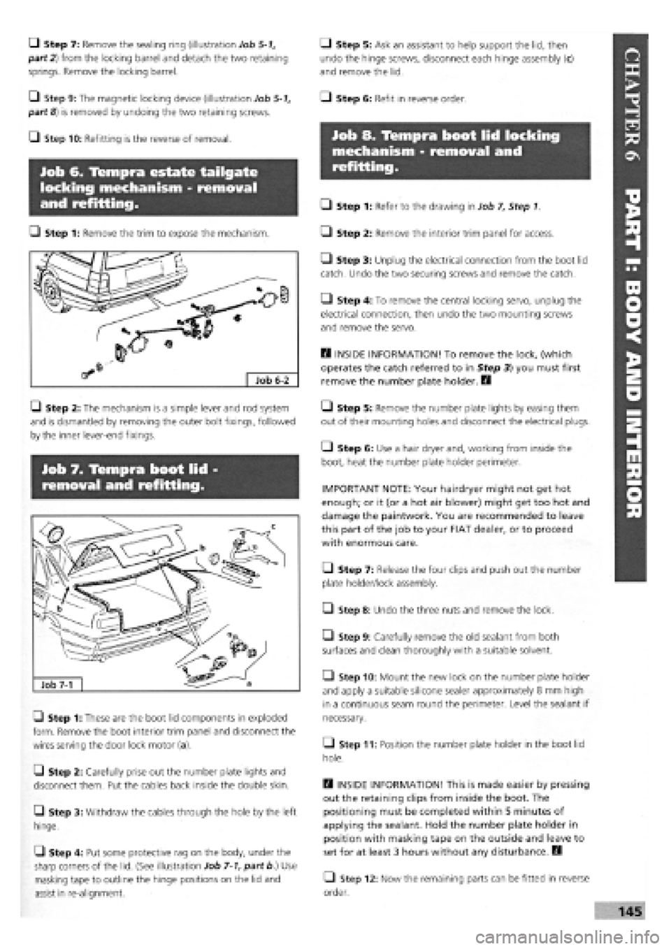
Q Step 1: Remove the trim to expose the mechanism.
G Step 2: The mechanism is a simple lever and rod system
and is dismantled by removing the outer bolt fixings, followed
by the inner lever-end fixings.
Job 7. Tempra boot lid -
removal and refitting.
Q Step 1: These are the boot lid components in exploded
form. Remove the boot interior trim panel and disconnect the
wires serving the door lock motor (a).
G Step 2: Carefully prise out the number plate lights and
disconnect them. Put the cables back inside the double skin.
Q Step 3: Withdraw the cables through the hole by the left
hinge.
L) Step 4: Put some protective rag on the body, under the
sharp corners of the lid. (See illustration Job
7-1,
part b.) Use
masking tape to outline the hinge positions on the lid and
assist in re-alignment.
Q Step 5: Ask an assistant to help support the lid, then
undo the hinge screws, disconnect each hinge assembly (c)
and remove the lid.
Q Step 6: Refit in reverse order.
Job 8. Tempra boot lid locking
mechanism - removal and
refitting.
Q Step 1: Refer to the drawing in Job 7, Step 1.
• Step 2: Remove the interior trim panel for access.
Q Step 3: Unplug the electrical connection from the boot lid
catch. Undo the two securing screws and remove the catch.
Q Step 4: To remove the central locking servo, unplug the
electrical connection, then undo the two mounting screws
and remove the servo.
Q INSIDE INFORMATION! To remove the lock, (which
operates the catch referred to in Step 3) you must first
remove the number plate holder. B
Q Step 5: Remove the number plate lights by easing them
out of their mounting holes and disconnect the electrical plugs.
Gl Step 6: Use a hair dryer and, working from inside the
boot, heat the number plate holder perimeter.
IMPORTANT NOTE: Your hairdryer might not get hot
enough; or it (or a hot air blower) might get too hot and
damage the paintwork. You are recommended to leave
this part of the job to your FIAT dealer, or to proceed
with enormous care.
• Step 7: Release the four clips and push out the number
plate holder/lock assembly.
• Step 8: Undo the three nuts and remove the lock.
Q Step 9: Carefully remove the old sealant from both
surfaces and clean thoroughly with a suitable solvent.
• Step 10: Mount the new lock on the number plate holder
and apply a suitable silicone sealer approximately 8 mm high
in a continuous seam round the perimeter. Level the sealant if
necessary.
• Step 11: Position the number plate holder in the boot lid
hole.
H INSIDE INFORMATION! This is made easier by pressing
out the retaining clips from inside the boot. The
positioning must be completed within 5 minutes of
applying the sealant. Hold the number plate holder in
position with masking tape on the outside and leave to
set for at least 3 hours without any disturbance. D
Q Step 12: Now the remaining parts can be fitted in reverse
order.
Page 142 of 171
Job 9. Front bumper -
removal and refitting.
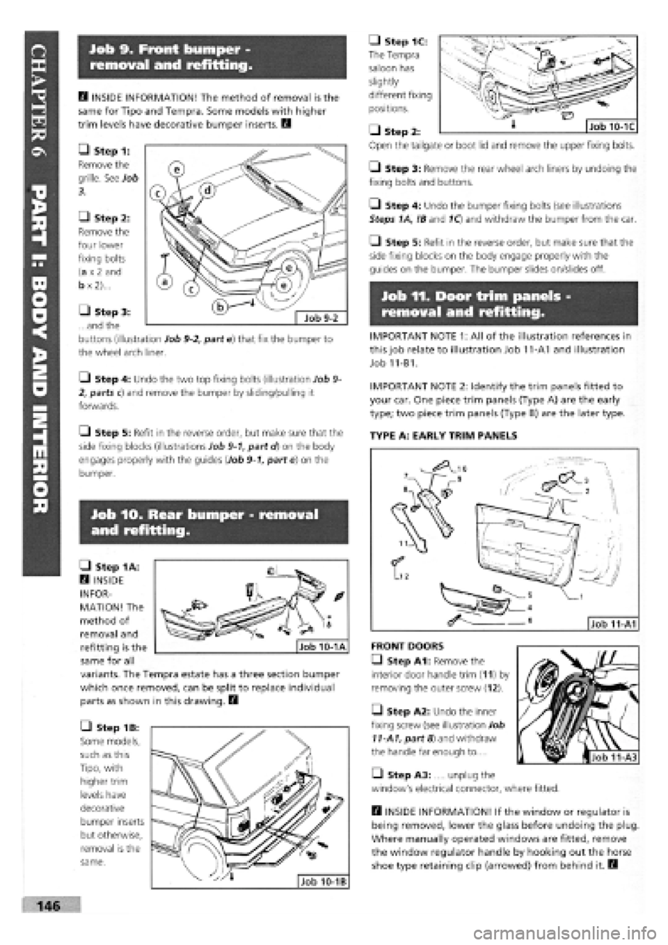
• Step 1C:
The Tempra
saloon has
slightly
different fixing
positions.
• Step
Open the
Q Step 3: Remove the rear wheel arch liners by undoing the
fixing bolts and buttons.
• Step 4: Undo the bumper fixing bolts (see illustrations
Steps 1A, !B and 1Q and withdraw the bumper from the car.
• Step 5: Refit in the reverse order, but make sure that the
side fixing blocks on the body engage properly with the
guides on the bumper. The bumper slides on/slides off.
Job 11. Door trim panels -
removal and refitting.
IMPORTANT NOTE 1: All of the illustration references in
this job relate to illustration Job 11-A1 and illustration
Job 11-B1.
IMPORTANT NOTE 2: Identify the trim panels fitted to
your car. One piece trim panels (Type A) are the early
type; two piece trim panels (Type B) are the later type.
TYPE A: EARLY TRIM PANELS
Job lO. Rear bumper - removal
and refitting.
H INSIDE INFORMATION! The method of removal is the
same for Tipo and Tempra. Some models with higher
trim levels have decorative bumper inserts. B
• Step 1:
Remove the
grille. See Job
3.
• Step 2:
Remove the
four lower
fixing bolts
(a
x 2
and
b
x
2)...
• Step 3:
...and the
buttons (illustration Job
9-2,
part e) that fix the bumper to
the wheel arch liner.
Q Step 4: Undo the two top fixing bolts (illustration Job
9-
2, parts c) and remove the bumper by sliding/pulling it
forwards.
Q Step 5: Refit in the reverse order, but make sure that the
side fixing blocks (illustrations Job
9-1,
part d) on the body
engages properly with the guides (Job
9-1,
part e) on the
bumper.
• Step 1A:
Q INSIDE
INFOR-
MATION! The
method of
removal and
refitting is the
same for all
variants. The Tempra estate has a three section bumper
which once removed, can be split to replace individual
parts as shown in this drawing. B
• Step 1B:
Some models,
such as this
Tipo, with
higher trim
levels have
decorative
bumper inserts
but otherwise,
removal is the
same.
FRONT DOORS
• Step A1: Remove the
interior door handle trim (11) by
removing the outer screw (12).
• Step A2: Undo the inner
fixing screw (see illustration Job
11-A1,
part 8) and withdraw
the handle far enough to....
• Step A3: .... unplug the
window's electrical connector, where fitted.
B INSIDE INFORMATION! If the window or regulator is
being removed, lower the glass before undoing the plug
Where manually operated windows are fitted, remove
the window regulator handle by hooking out the horse
shoe type retaining clip (arrowed) from behind it. B
2:
tailgate or boot lid and remove the upper fixing bolts.
MMBBMHHi 146
Page 143 of 171
Job 12. Door components,
removal and replacement.
Q Step B1: Undo the four screws
(6)
and remove the door
pocket (5).
Q Step B2: Carefully lever off the door handle trim (see illus-
tration Job 11-B1, part 11).
Q Step B3: Undo the three screws (11-B1, part 12
-
positions
arrowed) and withdraw the handle (11-B1, part 10) enough to....
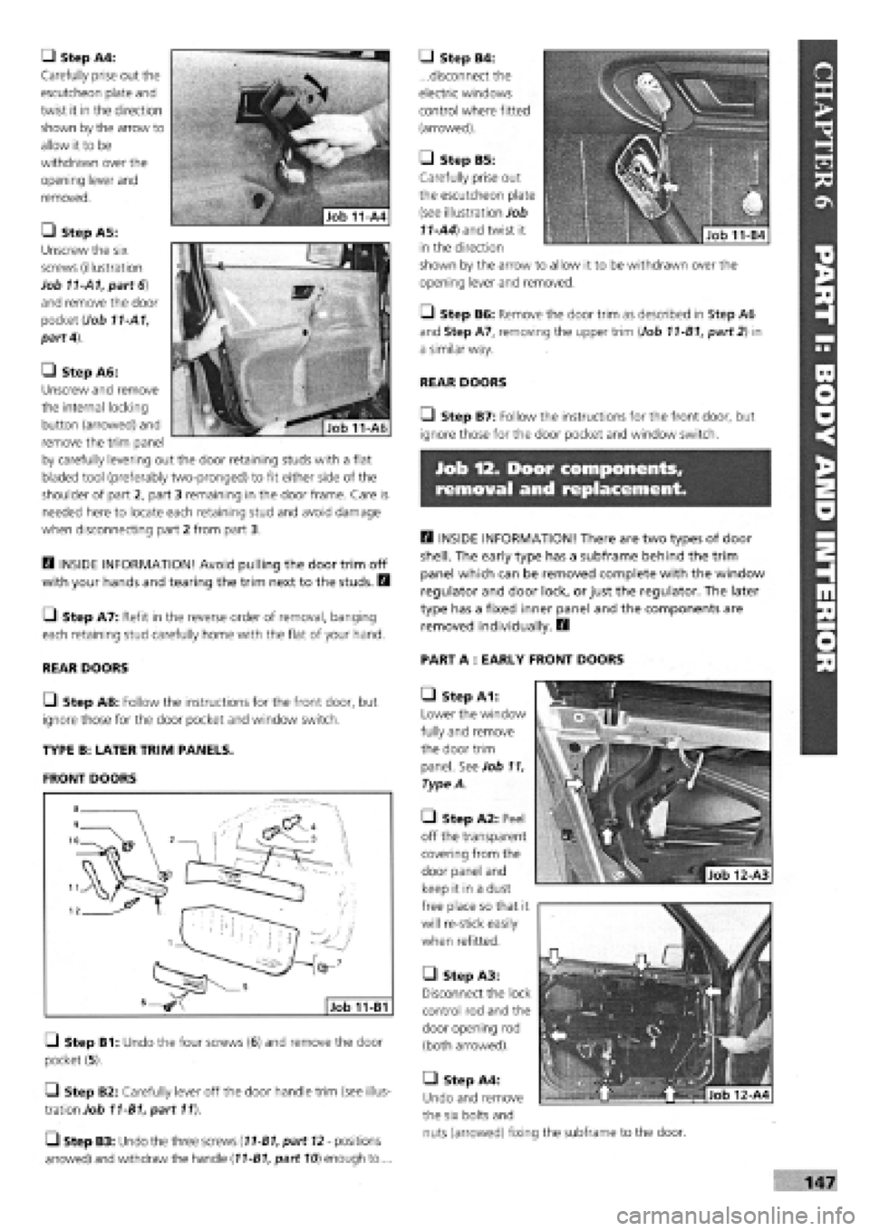
• Step A4:
Carefully prise out the
escutcheon plate and
twist it in the direction
shown by the arrow to
allow it to be
withdrawn over the
opening lever and
removed.
• Step A5:
Unscrew the six
screws (illustration
Job 11-A1, part 6)
and remove the door
pocket (Job 11-A1,
part 4).
• Step A6:
Unscrew and remove
the internal locking
button (arrowed) and
remove the trim panel
by carefully levering out the door retaining studs with a flat
bladed tool (preferably two-pronged) to fit either side of the
shoulder of part 2, part 3 remaining in the door frame. Care is
needed here to locate each retaining stud and avoid damage
when disconnecting part 2 from part 3.
H INSIDE INFORMATION! Avoid pulling the door trim off
with your hands and tearing the trim next to the studs. H
C_) Step A7: Refit in the reverse order of removal, banging
each retaining stud carefully home with the flat of your hand.
REAR DOORS
Q Step A8: Follow the instructions for the front door, but
ignore those for the door pocket and window switch.
TYPE B: LATER TRIM PANELS.
FRONT DOORS
• Step B6: Remove the door trim as described in Step A6
and Step A7, removing the upper trim (Job 11-B1, part 2) in
a similar way.
REAR DOORS
• Step B7: Follow the instructions for the front door, but
ignore those for the door pocket and window switch.
the six bolts and
nuts (arrowed) fixing the subframe to the door.
H INSIDE INFORMATION! There are two types of door
shell. The early type has a subframe behind the trim
panel which can be removed complete with the window
regulator and door lock, or just the regulator. The later
type has a fixed inner panel and the components are
removed individually. B
PART A : EARLY FRONT DOORS
• Step A1:
Lower the window
fully and remove
the door trim
panel. See Job 11,
Type A.
• Step A2: Peel
off the transparent
covering from the
door panel and
keep it in a dust
free place so that it
will re-stick easily
when refitted.
• Step A3:
Disconnect the lock
control rod and the
door opening rod
(both arrowed).
• Step A4:
Undo and remove
• Step B4:
...disconnect the
electric windows
control where fitted
(arrowed).
• Step B5:
Carefully prise out
the escutcheon plate
(see illustration Job
11-A4) and twist it
in the direction
shown by the arrow to allow it to be withdrawn over the
opening lever and removed.
Page 144 of 171
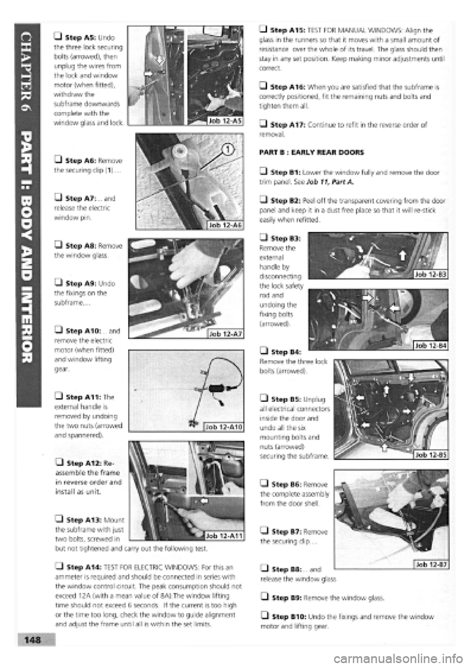
• Step A5: Undo
the three lock securing
bolts (arrowed), then
unplug the wires from
the lock and window
motor (when fitted),
withdraw the
subframe downwards
complete with the
window glass and lock.
[J Step A6: Remove
the securing clip (1)....
• Step A7: and
release the electric
window pin.
• Step A8: Remove
the window glass.
• Step A9: Undo
the fixings on the
subframe....
• Step A10:... and
remove the electric
motor (when fitted)
and window lifting
gear.
• Step A11: The
external handle is
removed by undoing
the two nuts (arrowed
and spannered).
• Step A12: Re-
assemble the frame
in reverse order and
install as unit.
• Step A13: Mount
the subframe with just
two bolts, screwed in
but not tightened and
<
out the following test.
• Step A14: TEST FOR ELECTRIC WINDOWS: For this an
ammeter is required and should be connected in series with
the window control circuit. The peak consumption should not
exceed 12A (with a mean value of 8A).The window lifting
time should not exceed 6 seconds. If the current is too high
or the time too long, check the window to guide alignment
and adjust the frame until all is within the set limits.
• Step B5: Unplug
all electrical connectors
inside the door and
undo all the six
mounting bolts and
nuts (arrowed)
securing the subframe.
Q Step B6: Remove
the complete assembly
from the door shell.
Q Step B7: Remove
the securing clip....
• Step A15: TEST FOR MANUAL WINDOWS: Align the
glass in the runners so that it moves with a small amount of
resistance over the whole of its travel. The glass should then
stay in any set position. Keep making minor adjustments until
correct.
• Step A16: When you are satisfied that the subframe is
correctly positioned, fit the remaining nuts and bolts and
tighten them all.
Q Step A17: Continue to refit in the reverse order of
removal.
PART B : EARLY REAR DOORS
• Step B1: Lower the window fully and remove the door
trim panel. See Job
11,
Part A.
• Step B2: Peel off the transparent covering from the door
panel and keep it in a dust free place so that it will re-stick
easily when refitted.
• Step B3:
Remove the
external
handle by
disconnecting
the lock safety
rod and
undoing the
fixing bolts
(arrowed).
• Step B4:
Remove the three lock
bolts (arrowed).
• Step B8: and
release the window glass
• Step B9: Remove the window glass.
Q Step B10: Undo the fixings and remove the window
motor and lifting gear.
Page 145 of 171
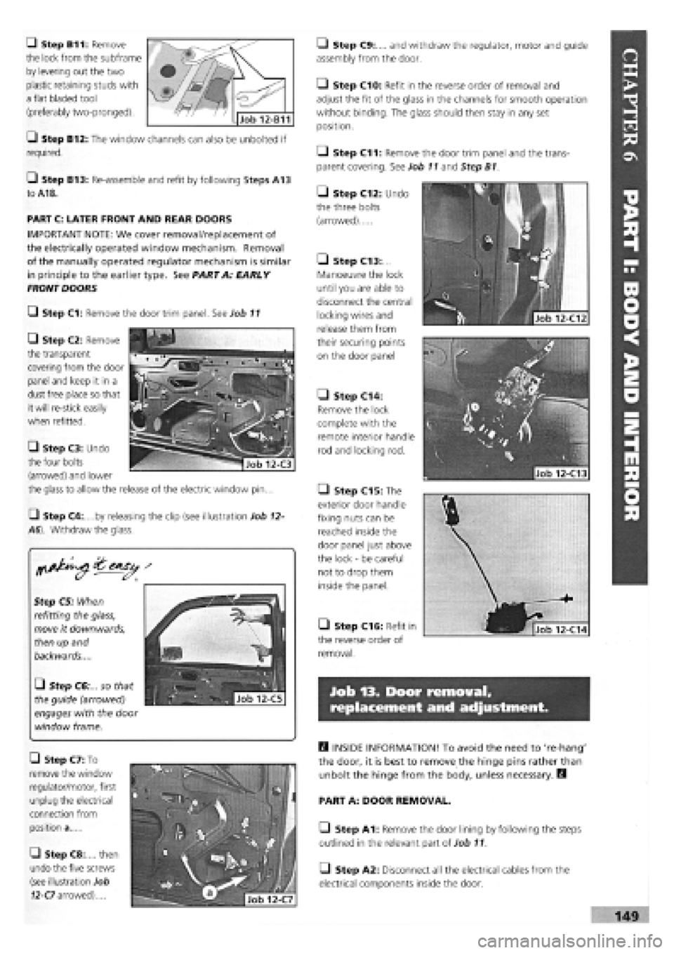
-J Step B11: Remove
the lock from the subframe
by levering out the two
plastic retaining studs with
a flat bladed tool
(preferably two-pronged).
• Step C13:...
Manoeuvre the lock
until you are able to
disconnect the central
locking wires and
release them from
their securing points
on the door panel
• Step C14:
Remove the lock
complete with the
remote interior handle
rod and locking rod.
• Step C15: The
exterior door handle
fixing nuts can be
reached inside the
door panel just above
the lock
-
be careful
not to drop them
inside the panel.
• Step C16: Refit in
the reverse order of
removal.
Q Step B12: The window channels can also be unbolted if
required.
Q Step B13: Re-assemble and refit by following Steps A13
to
A18.
PART C: LATER FRONT AND REAR DOORS
IMPORTANT NOTE: We cover removal/replacement of
the electrically operated window mechanism. Removal
of the manually operated regulator mechanism is similar
in principle to the earlier type. See PART A: EARLY
FRONTDOORS
Q Step C1: Remove the door trim panel. See Job 11
Q Step C2: Remove
the transparent
covering from the door
panel and keep it in a
dust free place so that
it will re-stick easily
when refitted.
• Step C3: Undo
the four bolts
• Step C9:.... and withdraw the regulator, motor and guide
assembly from the door.
• Step C10: Refit in the reverse order of removal and
adjust the fit of the glass in the channels for smooth operation
without binding. The glass should then stay in any set
position.
• Step C11: Remove the door trim panel and the trans-
parent covering. See Job 11 and Step B1.
• Step C12: Undo
the three bolts
(arrowed)
Step C5; When
refitting the glass,
move it downwards,
then up and
backwards....
• Step C6:... so that
the guide (arrowed)
engages with the door
window frame.
Q Step C4:....by releasing the clip (see illustration Job 12-
A6). Withdraw the glass.
(arrowed) and lower
the glass to allow the release of the electric window pin...
Job 13. Door removal,
replacement and adjustment.
• Step C7: To
remove the window
regulator/motor, first
unplug the electrical
connection from
position a
• Step C8:.... then
undo the five screws
(see illustration Job
12-C7 arrowed)....
B INSIDE INFORMATION! To avoid the need to 're-hang'
the door, it is best to remove the hinge pins rather than
unbolt the hinge from the body, unless necessary. B
PART A: DOOR REMOVAL.
LI Step A1: Remove the door lining by following the steps
outlined in the relevant part of Job 11.
• Step A2: Disconnect all the electrical cables from the
electrical components inside the door.
Page 146 of 171
B INSIDE INFORMATION! As an alternative to steps A1
and A2 you can disconnect all the electrical plugs under
the dashboard, which have wires which go through to
the door. B
LI Step A3: Support the door using a trolley jack with a
wad of rag on its pad for protection.
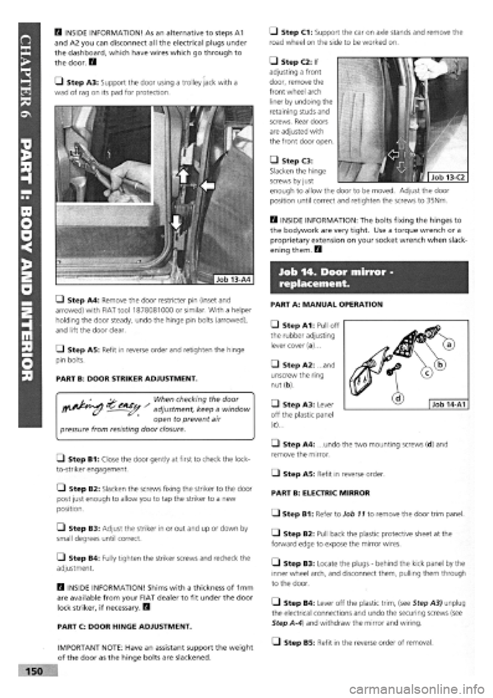
LI Step A4: Remove the door restricter pin (inset and
arrowed) with FIAT tool 1878081000 or similar. With a helper
holding the door steady, undo the hinge pin bolts (arrowed),
and lift the door clear.
• Step A5: Refit in reverse order and retighten the hinge
pin bolts.
PART B: DOOR STRIKER ADJUSTMENT.
, ' -u. When checking the door
jpj^ adjustment, keep a window
open to prevent air
pressure from resisting door closure.
• Step B1: Close the door gently at first to check the lock-
to-striker engagement.
• Step B2: Slacken the screws fixing the striker to the door
post just enough to allow you to tap the striker to a new
position.
L) Step B3: Adjust the striker in or out and up or down by
small degrees until correct.
Q Step B4: Fully tighten the striker screws and recheck the
adjustment.
B INSIDE INFORMATION! Shims with a thickness of 1mm
are available from your FIAT dealer to fit under the door
lock striker, if necessary. B
PART C: DOOR HINGE ADJUSTMENT.
IMPORTANT NOTE: Have an assistant support the weight
of the door as the hinge bolts are slackened.
• Step C1: Support the car on axle stands and remove the
road wheel on the side to be worked on.
• Step C2: If
adjusting a front
door, remove the
front wheel arch
liner by undoing the
retaining studs and
screws. Rear doors
are adjusted with
the front door open.
B INSIDE INFORMATION: The bolts fixing the hinges to
the bodywork are very tight. Use a torque wrench or a
proprietary extension on your socket wrench when slack-
ening them. B
Job 14. Door mirror -
replacement.
PART A: MANUAL OPERATION
• Step A1: Pull off
the rubber adjusting
lever cover (a)...
• Step A2: and
unscrew the ring
nut (b).
• Step A3: Lever
off the plastic panel
(c)...
• Step A4: ...undo the two mounting screws (d) and
remove the mirror.
D Step A5: Refit in reverse order.
PART B: ELECTRIC MIRROR
• Step B1: Refer to Job 11 to remove the door trim panel.
• Step B2: Pull back the plastic protective sheet at the
forward edge to expose the mirror wires.
• Step B3: Locate the plugs
-
behind the kick panel by the
inner wheel arch, and disconnect them, pulling them through
to the door.
• Step B4: Lever off the plastic trim, (see Step A3) unplug
the electrical connections and undo the securing screws (see
Step A-4) and withdraw the mirror and wiring.
LI Step B5: Refit in the reverse order of removal.
• Step C3:
Slacken the hinge
screws by just
enough to allow the door to be moved. Adjust the door
position until correct and retighten the screws to 35Nm.
Page 147 of 171
Job 15. Sun roof - removal and
refitting.
PART A: GENERAL
E3 INSIDE INFORMATION! If an electric sunroof fails to
work, it can be operated manually with the aid of a key
positioned behind the cover panel in the roof light
assembly. By engaging the key in the exposed drive pin,
you can turn it and adjust the roof position. Q
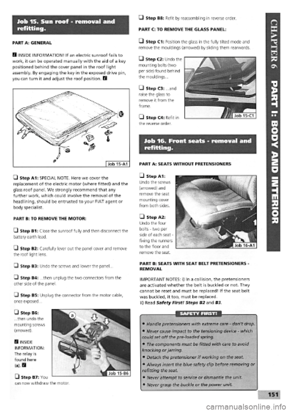
• Step A1: SPECIAL NOTE. Here we cover the
replacement of the electric motor (where fitted) and the
glass roof panel. We strongly recommend that any
further work, which could involve the removal of the
headlining, should be entrusted to your FIAT agent or
body specialist.
PART B: TO REMOVE THE MOTOR:
• Step B1: Close the sunroof fully and then disconnect the
battery earth lead.
Q Step B2: Carefully lever out the panel cover and remove
the roof light lens.
Q Step B3: Undo the screws and lower the panel...
G Step B4: ...then unplug the two connectors from the
other side of the panel.
O Step B5: Unplug the connector from the motor cable,
once exposed...
• Step B8: Refit by reassembling in reverse order.
PART C: TO REMOVE THE GLASS PANEL:
• Step C1: Position the glass in the fully tilted mode and
remove the mouldings (arrowed) by sliding them rearwards.
• Step C2: Undo the
mounting bolts (two
per side) found behind
the mouldings...
• Step C3: and
raise the glass to
remove it from the
frame.
• Step C4: Refit in
the reverse order.
Job 16. Front seats - removal and
refitting.
PART A: SEATS WITHOUT PRETENSIONERS
• Step A1:
Undo the screws
(arrowed) and
remove the seat
mounting cover
from both sides.
• Step A2:
Undo the four
bolts
-
two per
side of each seat
-
fixing the runners
to the floor and
remove the seat.
PART B: SEATS WITH SEAT BELT PRETENSIONERS -
REMOVAL
IMPORTANT NOTES: i) In a collision, the pretensioners
are activated whether the belt is buckled or not. They
cannot be reset and must be replaced! If the seat belt
was buckled, it too, must be replaced,
ii) Read Safety First! Steps B2 and B3.
he motor.
SAFETY FIRST!
• Handle pretensioners with extreme care
-
don't drop.
• Never cause impact to the tensioning device
-
which
could set off the pre-loaded spring.
• The components must be fitted with care to avoid
knocking or jarring.
• Detach the pretensioner if working on the seat.
• Always insert the blue safety clip before removing or
refitting the seat
• Never attempt to service or dismantle the unit
• Never grasp the buckle or the power unit
• Step B6:
...then undo the
mounting screws
(arrowed).
D INSIDE
INFORMATION:
The relay is
found here
(a).H
• Step B7: You
can now withdraw
Page 148 of 171
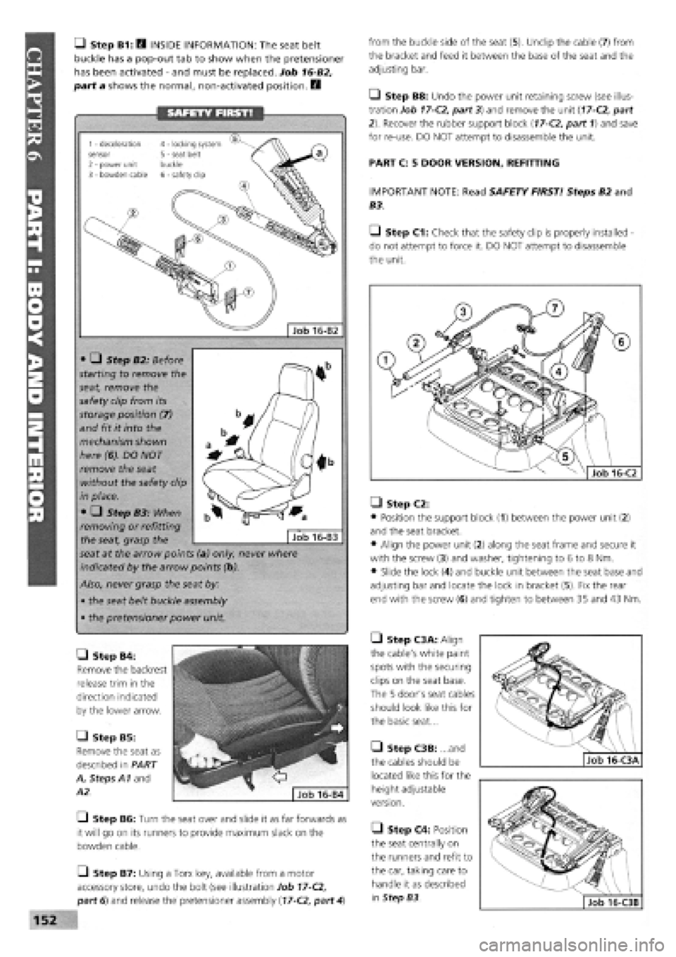
• Step B1: Q INSIDE INFORMATION: The seat belt
buckle has a pop-out tab to show when the pretensioner
has been activated
-
and must be replaced. Job 16-B2,
part a shows the normal, non-activated position. E3
from the buckle side of the seat (5). Unclip the cable (7) from
the bracket and feed it between the base of the seat and the
adjusting bar.
Q Step B8: Undo the power unit retaining screw (see illus-
tration Job
17-C2,
part 3) and remove the unit
(17-C2,
part
2). Recover the rubber support block
(17-C2,
part 1) and save
for re-use. DO NOT attempt to disassemble the unit.
PART C: 5 DOOR VERSION, REFITTING
IMPORTANT NOTE: Read SAFETY FIRST! Steps B2 and
B3.
Q Step C1: Check that the safety clip is properly installed -
do not attempt to force it. DO NOT attempt to disassemble
the unit.
• Step B4:
Remove the backrest
release trim in the
direction indicated
by the lower arrow.
• Step B5:
Remove the seat as
described in PART
A, Steps A1 and
A2.
—I Step B6: Turn the seat over and slide it as far forwards as
it will go on its runners to provide maximum slack on the
bowden cable.
O Step B7: Using a Torx key, available from a motor
accessory store, undo the bolt (see illustration Job
17-C2,
part 6) and release the pretensioner assembly
(17-C2,
part
4)
• Step C2:
• Position the support block (1) between the power unit (2)
and the seat bracket.
• Align the power unit (2) along the seat frame and secure it
with the screw (3) and washer, tightening to 6 to 8 Nm.
• Slide the lock (4) and buckle unit between the seat base and
adjusting bar and locate the lock in bracket (5). Fix the rear
end with the screw (6) and tighten to between 35 and 43 Nm.
• Step C3A: Align
the cable's white paint
spots with the securing
clips on the seat base.
The 5 door's seat cables
should look like this for
the basic seat...
• Step C3B: ...and
the cables should be
located like this for the
height adjustable
version.
• Step C4: Position
the seat centrally on
the runners and refit to
the car, taking care to
handle it as described
in Step B3.
SAFETY FIRST!
• • Step B2: Before
starting to remove the
seat, remove the
safety clip from its
storage position (7)
and fit it into the
mechanism shown
here (6). DO NOT
remove the seat
without the safety clip
in place.
• • Step B3: When
removing or refitting
the seat, grasp the
seat at the arrow points (a) only, never where
indicated by the arrow points (b).
Also, never grasp the seat by:
• the seat belt buckle assembly
• the pretensioner power unit.
Job 16-B3
• •
Job 16-B2
1 - deceleration sensor 2 - power unit 3 - bowden cable
4 - locking system 5 - seat belt buckle 6 - safety clip
Page 149 of 171
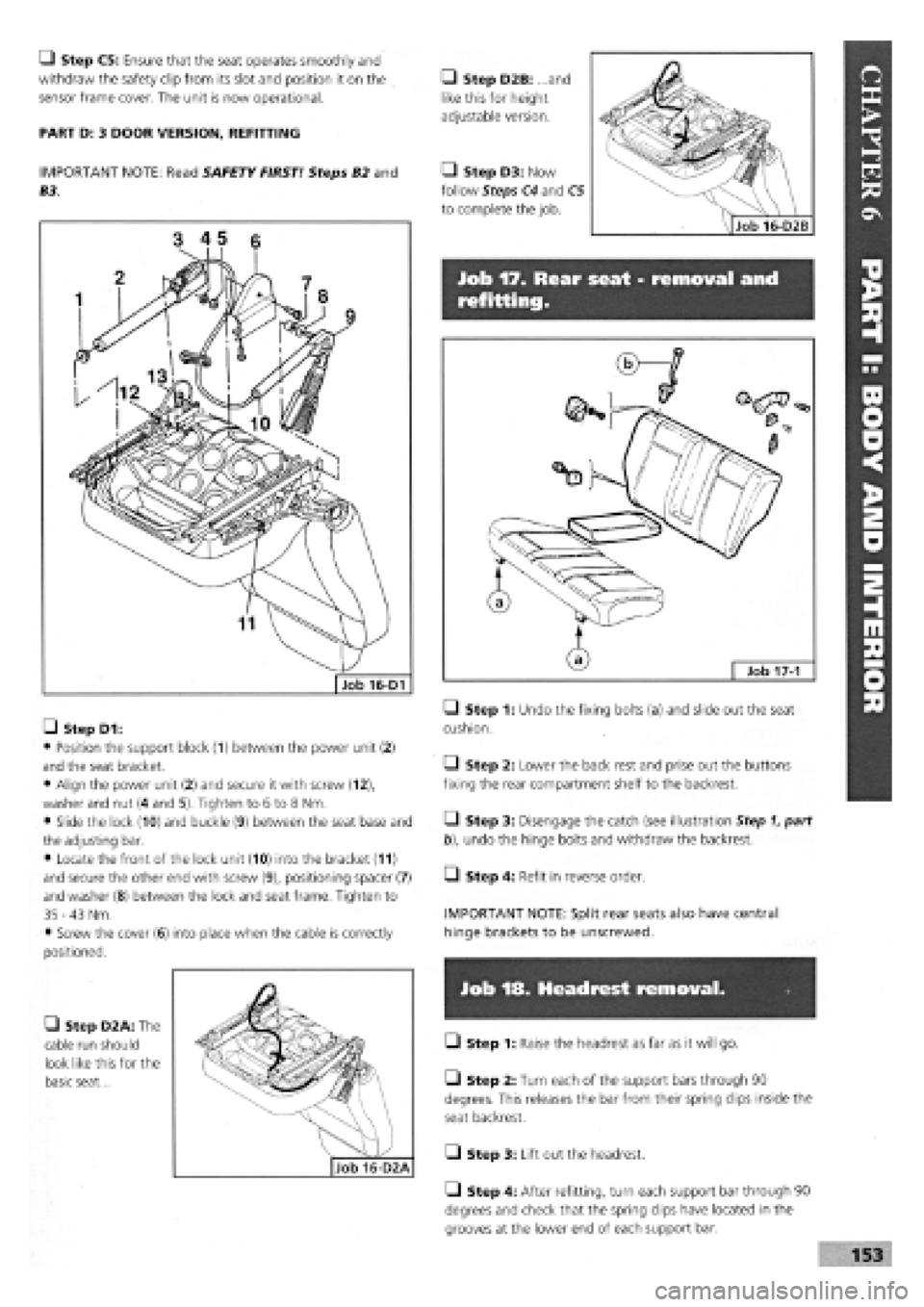
Job 17. Rear seat - removal and
refitting.
Job 16-D1
Q Step C5: Ensure that the seat operates smoothly and
withdraw the safety clip from its slot and position it on the
sensor frame cover. The unit is now operational.
PART D: 3 DOOR VERSION, REFITTING
IMPORTANT NOTE: Read SAFETY FIRST! Steps B2 and
B3.
• Step D2B: .. and
like this for height
adjustable version.
• Step D3: Now
follow Steps C4 and C5
to complete the job.
• Step D1:
• Position the support block (1) between the power unit (2)
and the seat bracket.
• Align the power unit (2) and secure it with screw (12),
washer and nut (4 and 5). Tighten to 6 to 8 Nm.
• Slide the lock (10) and buckle (9) between the seat base and
the adjusting bar.
• Locate the front of the lock unit (10) into the bracket (11)
and secure the other end with screw (9), positioning spacer (7)
and washer
(8)
between the lock and seat frame. Tighten to
35 -43
Nm.
• Screw the cover
(6)
into place when the cable is correctly
positioned.
• Step D2A: The
cable run should
look like this for the
basic seat...
• Step 1: Undo the fixing bolts (a) and slide out the seat
cushion.
Q Step 2: Lower the back rest and prise out the buttons
fixing the rear compartment shelf to the backrest.
• Step 3: Disengage the catch (see illustration Step 1, part
b), undo the hinge bolts and withdraw the backrest.
Q Step 4: Refit in reverse order.
IMPORTANT NOTE: Split rear seats also have central
hinge brackets to be unscrewed.
Job 18. Headrest removal.
• Step 1: Raise the headrest as far as it will go.
• Step 2: Turn each of the support bars through 90
degrees. This releases the bar from their spring clips inside the
seat backrest.
Q Step 3: Lift out the headrest.
Q Step 4: After refitting, turn each support bar through 90
degrees and check that the spring clips have located in the
grooves at the lower end of each support bar.
Page 150 of 171
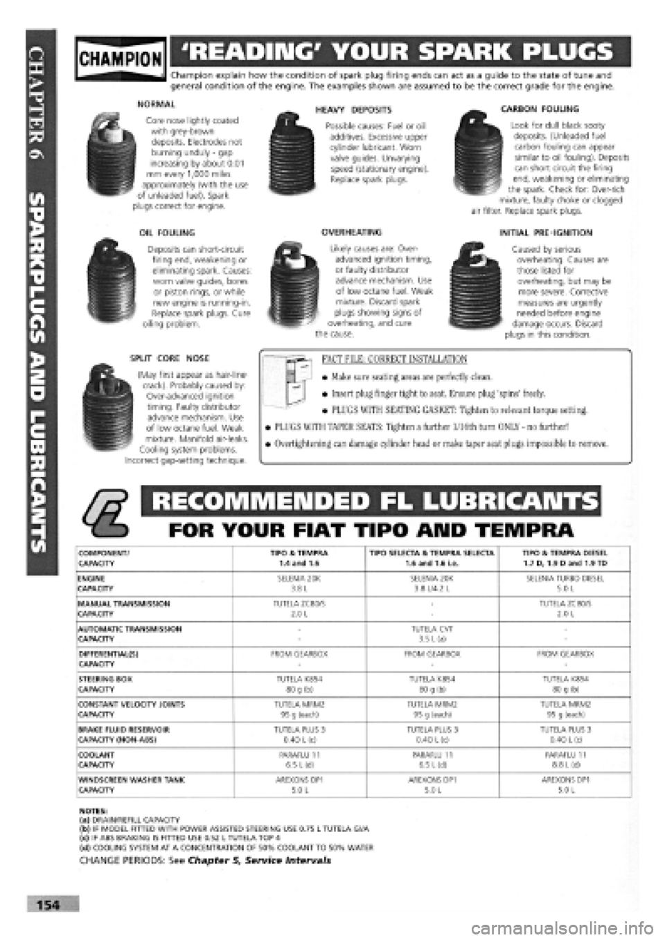
gjpjgjjl 'READING' YOUR SPARK PLUGS
Champion explain how the condition of spark plug firing ends can act as a guide to the state of tune and general condition of the engine. The examples shown are assumed to be the correct grade for the engine.
NORMAL
Core nose lightly coated with grey-brown deposits. Electrodes not burning unduly
-
gap increasing by about 0.01 mm every 1,000 miles approximately (with the use of unleaded fuel). Spark plugs correct for engine.
OIL FOULING
Deposits can short-circuit firing end, weakening or eliminating spark. Causes: worn valve guides, bores or piston rings, or while new engine is running-in. Replace spark plugs. Cure oiling problem.
SPLIT CORE NOSE
(May first appear as hair-line-crack). Probably caused by: Over-advanced ignition timing. Faulty distributor advance mechanism. Use of low octane fuel. Weak mixture. Manifold air-leaks. Cooling system problems. Incorrect gap-setting technique.
HEAVY DEPOSITS
Possible causes: Fuel or oil additives. Excessive upper cylinder lubricant. Worn valve guides. Unvarying speed (stationary engine). Replace spark plugs.
OVERHEATING
Likely causes are: Over-advanced ignition timing, or faulty distributor advance mechanism. Use of low octane fuel. Weak mixture. Discard spark plugs showing signs of overheating, and cure the cause.
CARBON FOULING
Look for dull black sooty deposits. (Unleaded fuel carbon fouling can appear similar to oil fouling). Deposits can short circuit the firing end, weakening or eliminating the spark. Check for: Over-rich mixture, faulty choke or clogged air filter. Replace spark plugs.
INITIAL PRE-IGNITION
Caused by serious overheating. Causes are those listed for overheating, but may be more severe. Corrective measures are urgently needed before engine damage occurs. Discard plugs in this condition.
FACT FILE: CORRECT INSTALLATION
• Make sure seating areas are perfectly clean.
• Insert plug finger tight to seat. Ensure plug 'spins' freely.
• PLUGS WITH SEATING GASKET: Tighten to relevant torque setting.
• PLUGS WITH TAPER SEATS: Tighten a further l/16th turn ONLY - no further!
• Overtightening can damage cylinder head or make taper seat plugs impossible to remove.
RECOMMENDED FL LUBRICANTS
FOR YOUR FIAT TIPO ARID TEMPRA
COMPONENT/ TIPO & TEMPRA TIPO SELECTA & TEMPRA SELECTA TIPO & TEMPRA DIESEL CAPACITY 1.4 and 1.6 1.6 and 1.6 i.e. 1.7 D, 1.9 Dand 1.9 TD
ENGINE SELENIA 20K SELENIA 20K SELENIA TURBO DIESEL CAPACITY 3.8 L 3.8 L/4.2 L 5.0 L
MANUAL TRANSMISSION TUTELA ZC80/S -TUTELA ZC80/S CAPACITY 2.0 L -2.0 L
AUTOMATIC TRANSMISSION -TUTELA CVT -CAPACITY -3.5 L (a) -
DIFFERENTIAL(S) FROM GEARBOX FROM GEARBOX FROM GEARBOX CAPACITY ---
STEERING BOX TUTELA K854 TUTELA K854 TUTELA K854 CAPACITY 80 g (b) 80 g (b) 80 g (b)
CONSTANT VELOCITY JOINTS TUTELA MRM2 TUTELA MRM2 TUTELA MRM2 CAPACITY 95 g (each) 95 g (each) 95 g (each)
BRAKE FLUID RESERVOIR TUTELA PLUS 3 TUTELA PLUS 3 TUTELA PLUS 3 CAPACITY (NON-ABS) 0.40
L
(c) 0.40 L (c) 0.40
L
(c)
COOLANT PARAFLU 11 PARAFLU 11 PARAFLU 11 CAPACITY 6.5 L(d) 6.5 L(d) 8.8
L
(d)
WINDSCREEN WASHER TANK AREXONS DP1 AREXONS DP1 AREXONS DP1 CAPACITY 5.0 L 5.0 L 5.0 L
NOTES: (a) DRAIN/REFILL CAPACITY (b) IF MODEL FITTED WITH POWER ASSISTED STEERING USE 0.75 L TUTELA Gl/A (c) IF ABS BRAKING IS FITTED USE 0.52 L TUTELA TOP 4 (d) COOLING SYSTEM AT A CONCENTRATION OF 50% COOLANT TO 50% WATER
CHANGE PERIODS: See Chapter 5, Service Intervals
154