FIAT TEMPRA 1988 Service And Repair Manual
Manufacturer: FIAT, Model Year: 1988, Model line: TEMPRA, Model: FIAT TEMPRA 1988Pages: 171, PDF Size: 18.05 MB
Page 121 of 171
s • F°r thenext tw° 5tep,s y°u
" (/ will require special tools
No.
1860765000
and No.
1842128000
to lock the sprocket and then remove it. If
you cannot hire these from your FIAT dealer you will
have
to adapt existing tools that will function correctly
and
not
cause
damage. Otherwise, have your properly
equipped
FIAT dealer carry out the work for you.
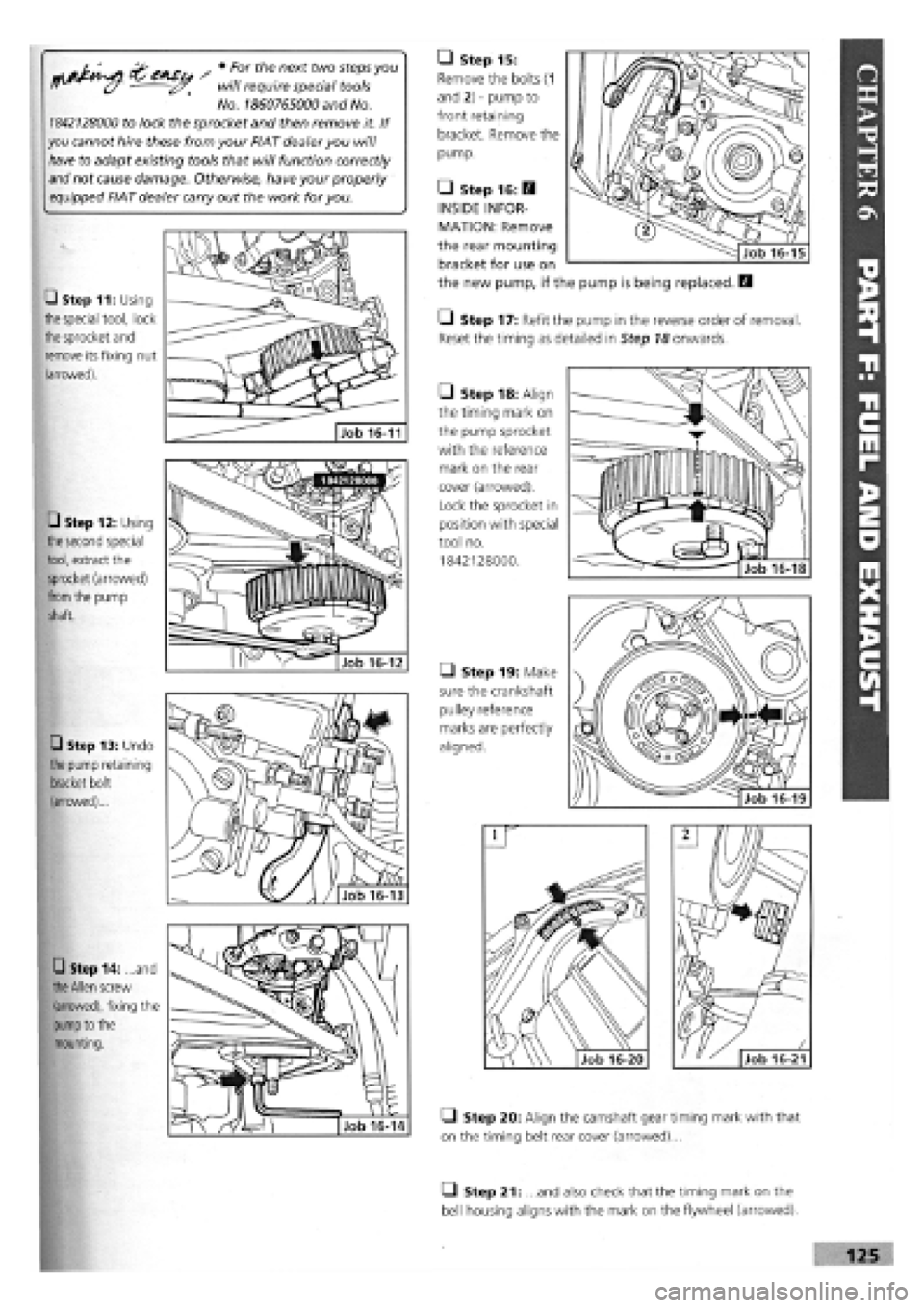
• Step 11: Using
the
special tool, lock
the
sprocket and
remove its fixing nut
(arrowed).
• Step 12: Using
the second
special
tool, extract the
sprocket (arrowed)
from
the pump
shaft.
• Step 13: Undo
the
pump retaining
bracket bolt
(arrowed)...
• Step 14: ...and
the Allen
screw
(arrowed), fixing the
pump
to the
mounting.
Job 16-11
• Step 20: Align the camshaft gear timing mark with that
on the timing belt rear cover (arrowed)...
• Step 15:
Remove the bolts (1
and 2)
-
pump to
front retaining
bracket. Remove the
pump.
• Step 19: Make
sure the crankshaft
pulley reference
marks are perfectly
aligned.
• Step 17: Refit the pump in the reverse order of removal.
Reset the timing as detailed in Step 18 onwards.
• Step 18: Align
the timing mark on
the pump sprocket
with the reference
mark on the rear
cover (arrowed).
Lock the sprocket in
position with special
tool no.
1842128000.
• Step 16: Q
INSIDE INFOR-
MATION: Remove
the rear mounting
bracket for use on
the new pump, if the pump is being replaced. E3
Q Step 21: ...and also check that the timing mark on the
bell housing aligns with the mark on the flywheel (arrowed).
Page 122 of 171
• Step 22: Inspect the timing belt and if
-
• it is contaminated with any liquid,
• has damaged teeth,
• or frayed edges,
• or it has covered more than 30000 km,
-
fit a new one.
D INSIDE INFORMATION: Some FIAT mechanics
recommend that the belt is replaced as a matter of
course. The cost of a new belt compared to the cost
of a damaged engine, makes it a false economy not to
do so.
E9
Q Step 23: Place the timing belt over the sprockets,
keeping it tight on the run between the pump and camshaft.
Q Step 24: Push the adjusting pulley into the belt and nip
up the lock nut. Without the aid of the special tool, the
adjustment is roughly correct when you can twist the belt at
its longest point between thumb and finger through a quarter
turn (90 degrees).
• Step 25: Turn the engine two full revolutions, re-check
the timing and belt tension. Adjust if necessary and tighten
the adjusting pulley lock nut.
B INSIDE INFORMATION! CHECKING INJECTION
ADVANCE. This cannot be done without the use of a dial
gauge and special adapter to fit on the rear of the
pump. We strongly recommend that although your
engine may seem to be running well, you get it checked
by your FIAT dealer. B
Job 17. Diesel injectors -
remove and refit.
Q Step 1: Clean thoroughly around each injector to prevent
dirt from entering the cylinders when removing the injectors.
Q Step 2: Unscrew the fuel pipe union at the injector, using
a flare nut wrench (split ring spanner).
• Step 3: Loosen the union at the injection-pump-end of
each injector pipe. Disconnect the fuel-return unions at the
injector and move the return pipes away.
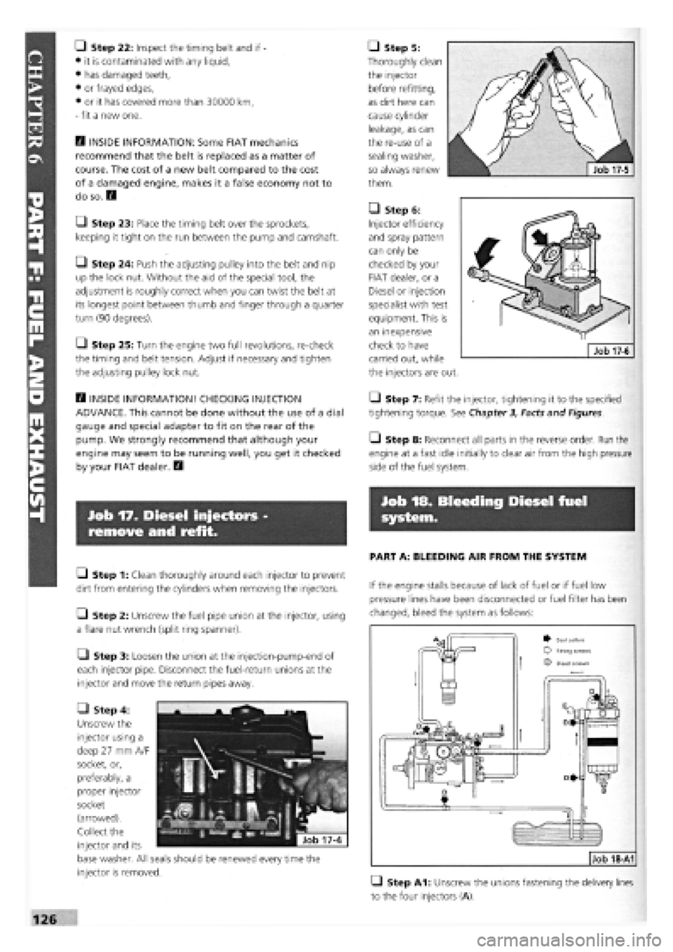
• Step 4:
Unscrew the
injector using a
deep 27 mm A/F
socket, or,
preferably, a
proper injector
socket
(arrowed).
Collect the
injector and its
base washer. All seals should be renewed every time the
injector is removed.
• Step 5:
Thoroughly clean
the injector
before refitting,
as dirt here can
cause cylinder
leakage, as can
the re-use of a
sealing washer,
so always renew
them.
• Step 6:
Injector efficiency
and spray pattern
can only be
checked by your
FIAT dealer, or a
Diesel or injection
specialist with test
equipment. This is
an inexpensive
check to have
carried out, while
the injectors are out.
• Step 7: Refit the injector, tightening it to the specified
tightening torque. See Chapter 3, Facts and Figures.
• Step 8: Reconnect all parts in the reverse order. Run the
engine at a fast idle initially to clear air from the high pressure
side of the fuel system.
Job 18. Bleeding Diesel fuel
system.
PART A: BLEEDING AIR FROM THE SYSTEM
If the engine stalls because of lack of fuel or if fuel low
pressure lines have been disconnected or fuel filter has been
changed, bleed the system as follows:
• Step A1: Unscrew the unions fastening the delivery lines
to the four injectors (A).
Job 18-A1
^ Seal collars Fifing screws
O Bleed screws
Page 123 of 171
• Step A2: Start the engine and run until fluid emerges
from the loose injector fitting.
G Step A3: Keep the engine running and tighten the four
injector fittings.
B INSIDE INFORMATION: If the engine will not start,
check all fuel inlet pipe union points (see illustration Job
18-A1,
part D) and also the pipe fittings (Job 18-A1,
part E). Replace seal washers to eliminate the possibility
of air leaks. H
PART B: BLEEDING WATER FROM DIESEL
Bleed off water from the fuel filter as follows:
• Step B1: Unscrew the water bleed screw (Job 18-A1,
part B) under the filter.
• Step B2: Unscrew air bleed screw (Job 18-A1, part Q
above the filter.
• Step B3: Let water and fuel emerge until no more water
is present, then tighten, firstly the water bleed screw (B) under
filter, and then the air bleed screw (C) above the filter.
PART G: STEERING AND SUSPENSION
PART G: Contents
Job
1.
The systems explained.
Job
2.
Steering wheel
-
removal and refitting
Job 3. Track rod end balijoint
-
replacement.
Job
4.
Steering rack gaiter
-
replacement.
Job 5. Steering rack
-
replacement.
Job
6.
Power steering pump
-
removal and refitting
Job
7.
Lower wishbone
-
replacement.
Job 8. Bleeding the power steering.
Job 9. Front anti-roll bar
-
removal and refitting.
Job 10. Rear anti-roll bar (when fitted).
Job 11. Front shock absorber
-
replacement.
Job 12. Front wheel bearing
-
replacement.
Job 13. Rear shock absorbers and coil springs
-
replacement.
Job 14. Rear suspension and wheel bearings
-
replacement.
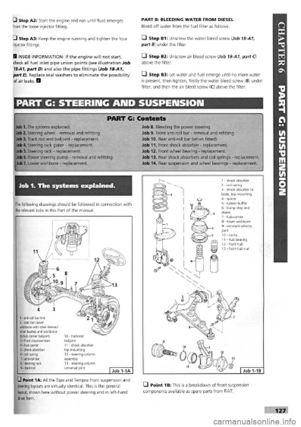
Job 1. The systems explained.
The
following drawings should be followed in connection with
the
relevant Jobs in this Part of the manual.
1
-
anti-roll bar link 2
-
cast iron lower wishbone with steel sleeved inner bushes and wishbone to hub carrier balijoint 3
-
front crossmember 4
-
hub carrier 5
-
shock absorber 6
-
coil spring 7
-
anti-roll bar 8
-
steering rack 9
-
trackrod
10 - trackrod balijoint 11 - shock absorber top mounting 12 - steering column assembly 13 - steering column universal joint Job 1-1A
G Point 1A: All the Tipo and Tempra front suspension and
steering layouts are virtually identical. This is the general LI Point 1B: This is a breakdown of front suspension
layout, shown here without power steering and in left-hand components available as spare parts from FIAT,
drive
form.
Page 124 of 171
Job 2. Steering wheel - removal
and refitting.
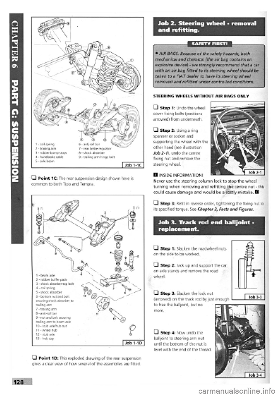
1 - coil spring 2 - trailing arm 3 - rubber bump stops 4 - handbrake cable 5 - axle beam
6 - anti-roll bar 7 - rear brake regulator 8 - shock absorber 9 - trailing arm hinge bolt
Job 1-1C
SAFETY FIRST!
• AIR BAGS. Because of the safety hazards, both
mechanical and chemical (the air bag contains an
explosive device)
-
we strongly recommend that a car
with an air bag fitted to its steering wheel should be
taken to a FIAT dealer to have its steering wheel
removed and refitted under controlled conditions.
STEERING WHEELS WITHOUT AIR BAGS ONLY
Q Point 1C: The rear suspension design shown here is
common to both Tipo and Tempra.
1 - beam axle 2 - rubber buffer pads 3 - shock absorber top bolt 4 - coil spring 5 - shock absorber 6 - bottom nut and bolt securing shock absorber to trailing arm 7 - trailing arm 8 - anti-roll bar 9 - nut and bolt securing trailing arm to beam axle 10 - stub axle/hub nut 11 - wheel hub 12 - stub axle 13
-
hub cap
Job 1-1D
Q Point 1D: This exploded drawing of the rear suspension
gives a clear view of how several of the assemblies are fitted.
• Step 3: Slacken the lock nut
(arrowed) on the track rod by just enough
to free the balljoint, but no
more.
• Step 4: Now undo the
balljoint to steering arm nut
until the bottom of the nut is
level with the end of the thread.
Job
3-3
Job 3. Track rod end balljoint -
replacement.
Q Step 1: Slacken the roadwheel nuts
on the side to be worked.
Q Step 2: Jack up and support the car
on axle stands and remove the road
wheel.
• Step 1: Undo the wheel
cover fixing bolts (positions
arrowed) from underneath.
• Step 2: Using a ring
spanner or socket and
supporting the wheel with the
other hand (see illustration
Job
2-1),
undo the centre
fixing nut and remove the
steering wheel.
H INSIDE INFORMATION!
Never use the steering column lock to stop the wheel
turning when removing and refitting the centre nut-this
could cause damage and would be a costly mistake. H
• Step 3: Refit in reverse order, tightening the fixing nut to
its specified torque. See Chapter
3,
Facts and Figures.
Page 125 of 171
Job 4. Steering rack gaiter -
replacement.
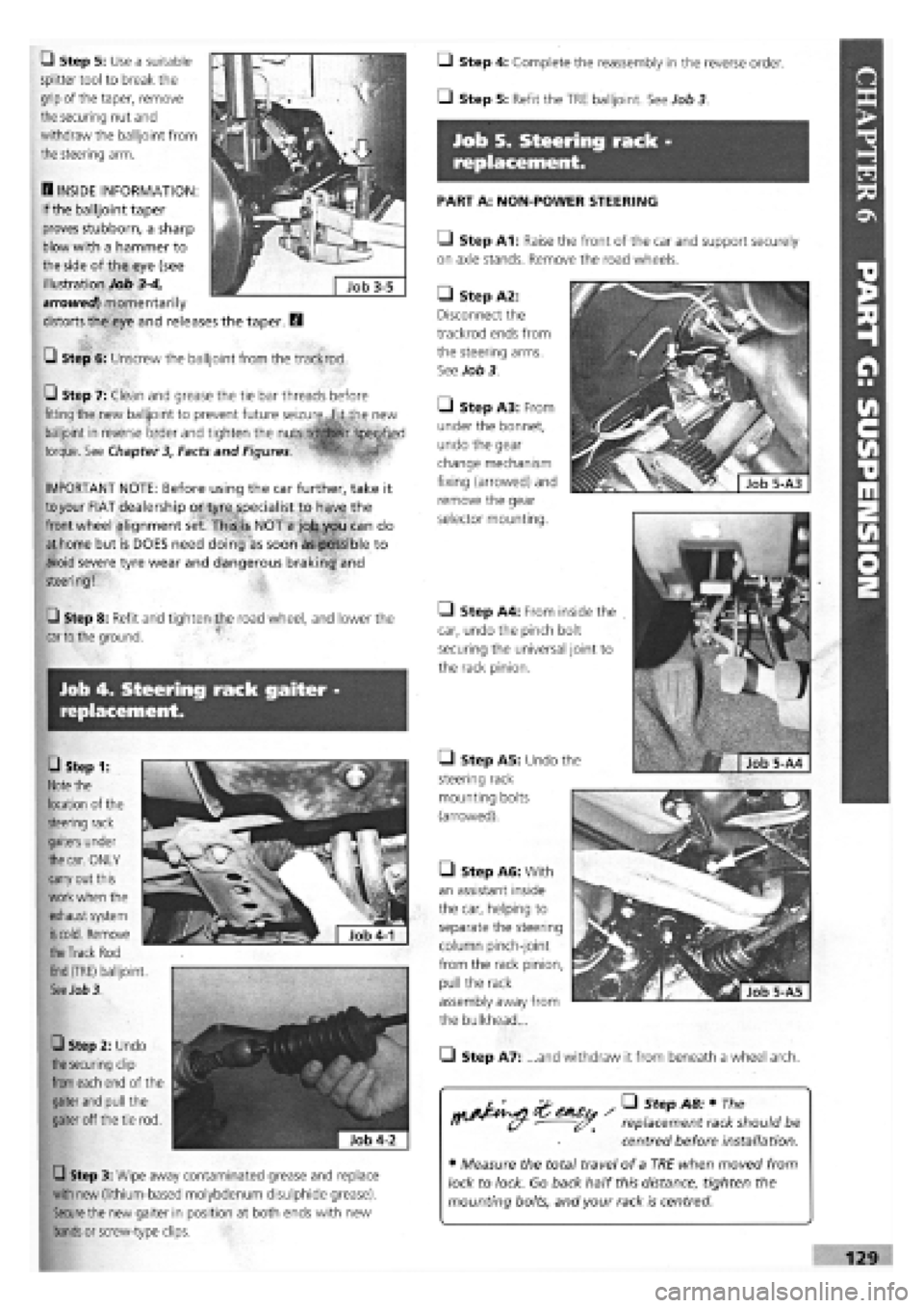
• Step 1:
Note
the
location of the
steering rack
gaiters under
the car.
ONLY
carry out this
work when the
exhaust system
is cold.
Remove
Q Step 5: Use a suitable
splitter tool to break the
grip of the taper, remove
the securing nut and
withdraw the balljoint from
the steering arm.
B INSIDE INFORMATION:
If the balljoint taper
proves stubborn, a sharp
blow with a hammer to
the side of the eye (see
illustration Job
3-4,
arrowed) momentarily
distorts the eye and releases the taper. B
G Step 6: Unscrew the balljoint from the trackrod.
Q Step 7: Clean and grease the tie bar threads before
fitting the new balljoint to prevent future seizure,.fit the new
balljoint in reverse order and tighten the
torque. See Chapter 3, Facts and Figures.
1 ' ™
IMPORTANT NOTE: Before using the car further, take it
to
your FIAT dealership or tyre specialist to have the
front wheel alignment set. This4s NOT a job you can do
at home but is DOES need doing as soon as possible to
avoid severe tyre wear and dangerous braking and
steering!
Q Step 8: Refit and tighten the road wheel, and lower the
car to
the ground.
Q Step 3: Wipe away contaminated grease and replace
with new (lithium-based molybdenum disulphide grease).
Secure
the new gaiter in position at both ends with new
bands
or screw-type clips.
the Track
Rod
End
(TRE) balljoint.
See Job 3.
0 Step 2: Undo
the securing
clip
from
each end of the
gaiter
and
pull the
gaiter off the tie rod.
Q Step 4: Complete the reassembly in the reverse order.
• Step 5: Refit the TRE balljoint. See Job 3
Job 5. Steering rack -
replacement.
PART A: NON-POWER STEERING
Q Step A1: Raise the front of the car and support securely
on axle stands. Remove the road wheels.
• Step A5: Undo the
steering rack
mounting bolts
(arrowed).
• Step A2:
Disconnect the
trackrod ends from
the steering arms.
See Job 3.
Q Step A3: From
under the bonnet,
undo the gear
change mechanism
fixing (arrowed) and
remove the gear
selector mounting.
• Step A4: From inside the
car, undo the pinch bolt
securing the universal joint to
the rack pinion.
• Step A6: With
an assistant inside
the car, helping to
separate the steering
column pinch-joint
from the rack pinion,
pull the rack
assembly away from
the bulkhead...
• Step A7: ...and withdraw it from beneath a wheel arch.
replacement rack should be
centred before installation.
• Measure the total travel of a TRE when moved from
lock to lock. Go back half this distance, tighten the
mounting bolts, and your rack is centred.
Page 126 of 171
Q Step A9: Place the steering wheel in the dead ahead
position and engage the rack pinion splines with the column
coupling.
Q Step A10: Continue refitting in the reverse order of
removal.
• Step A11: Take your car to your nearest FIAT dealership
or tyre specialist to have the front wheel alignment set before
using the car further. This is NOT a job you can do at home
but is DOES need doing as soon as possible to avoid severe
tyre wear and dangerous braking and steering!
PART B: POWER STEERING RACK
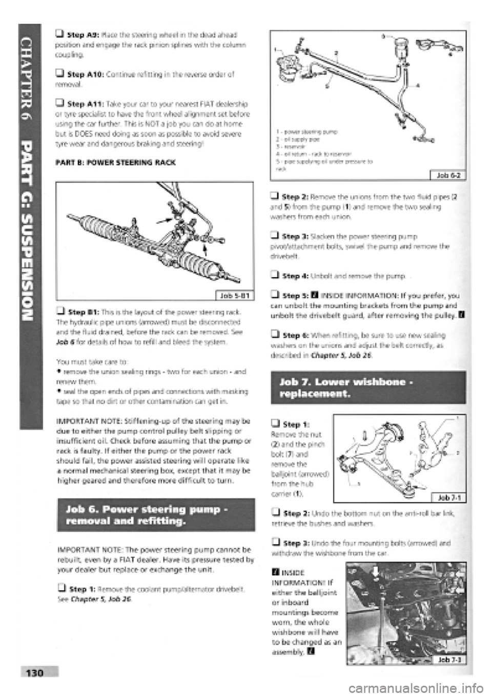
LI Step B1: This is the layout of the power steering rack.
The hydraulic pipe unions (arrowed) must be disconnected
and the fluid drained, before the rack can be removed. See
Job 6 for details of how to refill and bleed the system.
You must take care to:
• remove the union sealing rings
-
two for each union
-
and
renew them.
• seal the open ends of pipes and connections with masking
tape so that no dirt or other contamination can get in.
IMPORTANT NOTE: Stiffening-up of the steering may be
due to either the pump control pulley belt slipping or
insufficient oil. Check before assuming that the pump or
rack is faulty. If either the pump or the power rack
should fail, the power assisted steering will operate like
a normal mechanical steering box, except that it may be
higher geared and therefore more difficult to turn.
Job 6. Power steering pump
removal and refitting.
IMPORTANT NOTE: The power steering pump cannot be
rebuilt, even by a FIAT dealer. Have its pressure tested by
your dealer but replace or exchange the unit.
[_) Step 1: Remove the coolant pump/alternator drivebelt.
See Chapter
5,
Job 26.
• Step 2: Remove the unions from the two fluid pipes (2
and 5) from the pump (1) and remove the two sealing
washers from each union.
Q Step 3: Slacken the power steering pump
pivot/attachment bolts, swivel the pump and remove the
drivebelt.
• Step 4: Unbolt and remove the pump.
• Step 5: B INSIDE INFORMATION: If you prefer, you
can unbolt the mounting brackets from the pump and
unbolt the drivebelt guard, after removing the pulley. I
• Step 6: When refitting, be sure to use new sealing
washers on the unions and adjust the belt correctly, as
described in Chapter
5,
Job 26
Job 7. Lower wishbone
replacement.
• Step 1:
Remove the nut
(2) and the pinch
bolt (7) and
remove the
balljoint (arrowed)
from the hub
carrier (1).
• Step 2: Undo the bottom nut on the anti-roll bar link,
retrieve the bushes and washers.
• Step 3: Undo the four mounting bolts (arrowed) and
withdraw the wishbone from the car.
H INSIDE
INFORMATION! If
either the balljoint
or inboard
mountings become
worn, the whole
wishbone will have
to be changed as an
assembly. E3
130
1 - power steering pump 2 - oil supply pipe 3 - reservoir 4 - oil return - rack to reservoir 5 - pipe supplying oil under pressure to rack Job
6-2
Page 127 of 171
Q Step 4: Re-assemble in the reverse order using torque
settings shown in Chapter
3,
Facts and Figures
Job 8. Bleeding the power
steering.
The power assisted steering system is self-bleeding. You
should slowly apply full lock alternately to the right and left
with the car stationary and the engine running, while an
assistant tops up the reservoir. This operation should be
carried out each time the connecting pipes are removed or
refitted.
Job 9. Front anti-roll bar -
removal and refitting.
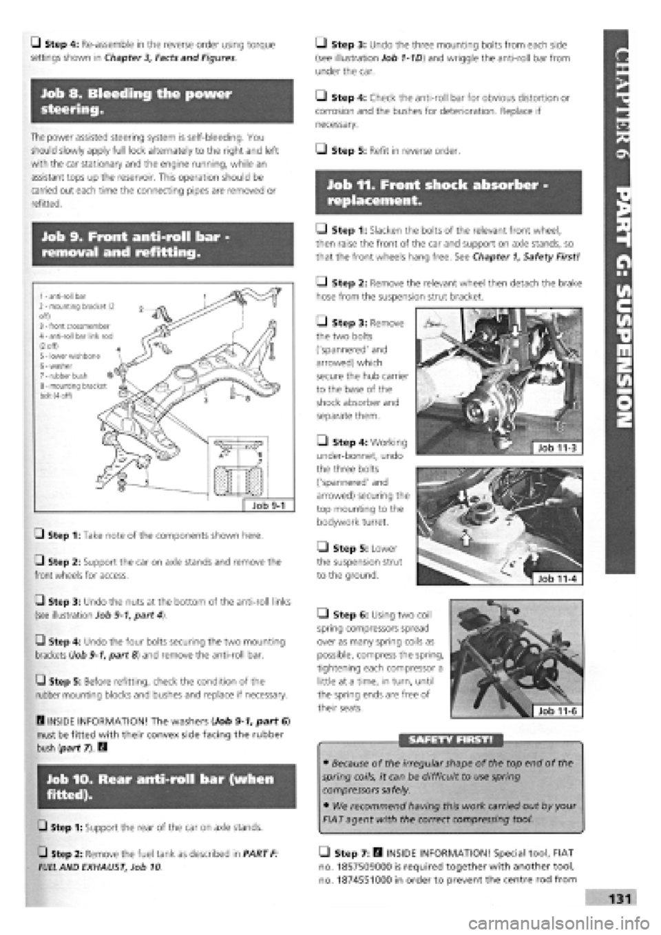
G Step 1: Take note of the components shown here.
G Step 2: Support the car on axle stands and remove the
front wheels for access.
G Step 3: Undo the nuts at the bottom of the anti-roll links
(see illustration Job
9-1,
part 4).
G Step 4: Undo the four bolts securing the two mounting
brackets (Job
9-1,
part 8) and remove the anti-roll bar.
G Step 5: Before refitting, check the condition of the
rubber mounting blocks and bushes and replace if necessary.
Q INSIDE INFORMATION! The washers (Job
9-1,
part 6)
must be fitted with their convex side facing the rubber
bush (part 7). B
lob 10. Rear anti-roll bar (when
fitted).
• Step 3: Undo the three mounting bolts from each side
(see illustration Job
1-1D)
and wriggle the anti-roll bar from
under the car.
• Step 4: Check the anti-roll bar for obvious distortion or
corrosion and the bushes for deterioration. Replace if
necessary.
I—J Step 5: Refit in reverse order.
Job 11. Front shock absorber -
replacement.
Q Step 1: Slacken the bolts of the relevant front wheel,
then raise the front of the car and support on axle stands, so
that the front wheels hang free. See Chapter
1,
Safety First!
Q Step 2: Remove the relevant wheel then detach the brake
hose from the suspension strut bracket.
• Step 3: Remove
the two bolts
('spannered' and
arrowed) which
secure the hub carrier
to the base of the
shock absorber and
separate them.
• Step 4: Working
under-bonnet, undo
the three bolts
('spannered' and
arrowed) securing the
top mounting to the
bodywork turret.
• Step 5: Lower
the suspension strut
to the ground.
• Step 6: Using two coil
spring compressors spread
over as many spring coils as
possible, compress the spring,
tightening each compressor a
little at a time, in turn, until
the spring ends are free of
their seats.
• Because of the irregular shape of the top end of the
spring coils, it can be difficult to use spring
compressors safely.
• We recommend having this work carried out by your
FIAT agent with the correct compressing tool. G Step 1: Support the rear of the car on axle stands.
Job 9-1
1
-
anti-roll bar 2
-
mounting bracket (2 off) 3
-
front crossmember 4
-
anti-roll bar link rod
(2
off) 5
-
lower wishbone 6
-
washer 7
-
rubber bush 8
-
mounting bracket bolt (4 off)
G Step 2: Remove the fuel tank as described in PART
F:
FUEL
AND EXHAUST, Job 10
• Step 7: B INSIDE INFORMATION! Special tool, FIAT
no. 1857509000 is required together with another tool,
no. 1874551000 in order to prevent the centre rod from
Page 128 of 171
turning while undoing the large nut that secures the top
mounting
-
or ask your FIAT dealer to do it for you. B
• Step 8: Refer to Job
1-1B.
Pull off the mounting (3),
spacer (4), rubber buffer (5), stop buffer and sleeve (6) and the
coil spring (2).
FACT FILE: COIL SPRINGS
If a coil spring is cracked, sagged or heavily
rusted, replace the front springs AS A PAIR.
FIAT springs are colour-coded with a stripe
of either yellow or green paint. Use only a
matching pair.
SAFETY FIRST!
• Never undo the centre nut (Steps 7 and 8) without
using a suitable spring compressor.
• The power contained within the spring is enormous
and extremely dangerous.
• If you are not trained or experienced in this part of
the job, leave it to your FIAT dealer.
Q Step 9: Refit all components in reverse order, making
sure the coil spring is properly seated with the large coil at the
bottom and the end of the coil, tight against the stop in the
spring seat. Tighten to the specified tightening torques (see
Chapter
3,
Facts and Figures) only when the car is back on
its wheels.
Job 12. Front wheel bearing
replacement.
IMPORTANT NOTE: The wheel bearing will probably be
destroyed as it is removed from the hub.
The hub and bearing can
be drifted out from the hub
carrier.
• If you have difficulty doing so, you could remove the
hub carrier and take it to your FIAT dealer for bearing
replacement.
• Step 1: H INSIDE INFORMATION:
• The hub nut (see illustration Job
12-9,
part f) requires
a great deal of torque to undo!
• Lever off the dust cap and slacken the centre hub nut
(see illustration Job 1-1B, part 13) while the car is still
on the ground.
• Try to lift the staking from the groove in the drive-
shaft. If it won't all come clear, don't worry! It will unroll
as the nut is undone.
• You will need an extra-long lever (about half-a-metre
long) to undo the hub nut.
• Slacken the wheel bolts while the car is on the
ground. H
Q Step 2: Raise and support the car on axle stands. Remove
the road wheel. Remove the hub/drive-shaft nut.
• Step 3: Undo the brake caliper and the bracket retaining
bolts. Move the caliper clear, still connected to the hose but
not putting weight on it. See PART H: BRAKES, Job 3.
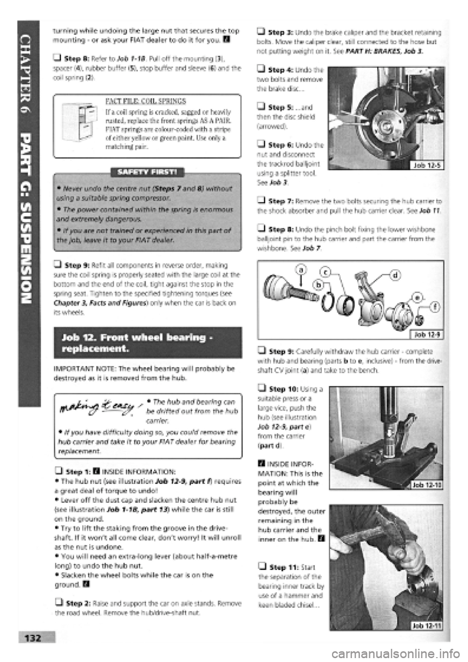
• Step 4: Undo the
two bolts and remove
the brake disc...
• Step 5: ...and
then the disc shield
(arrowed).
• Step 6: Undo the
nut and disconnect
the trackrod balijoint
using a splitter tool.
See Job 3.
Q Step 7: Remove the two bolts securing the hub carrier to
the shock absorber and pull the hub carrier clear. See Job
11.
• Step 8: Undo the pinch bolt fixing the lower wishbone
balijoint pin to the hub carrier and part the carrier from the
wishbone. See Job 7.
• Step 9: Carefully withdraw the hub carrier
-
complete
with hub and bearing (parts b to e, inclusive)
-
from the drive-
shaft CV joint (a) and take to the bench.
Q Step 10: Using a
suitable press or a
large vice, push the
hub (see illustration
Job
12-9,
part e)
from the carrier
(part d)
E3 INSIDE INFOR-
MATION: This is the
point at which the
bearing will
probably be
destroyed, the outer
remaining in the
hub carrier and the
inner on the hub. H
• Step 11: Start
the separation of the
bearing inner track by
use of a hammer and
keen bladed chisel...
Page 129 of 171
Job 13. Rear shock absorbers and
coil springs - replacement.
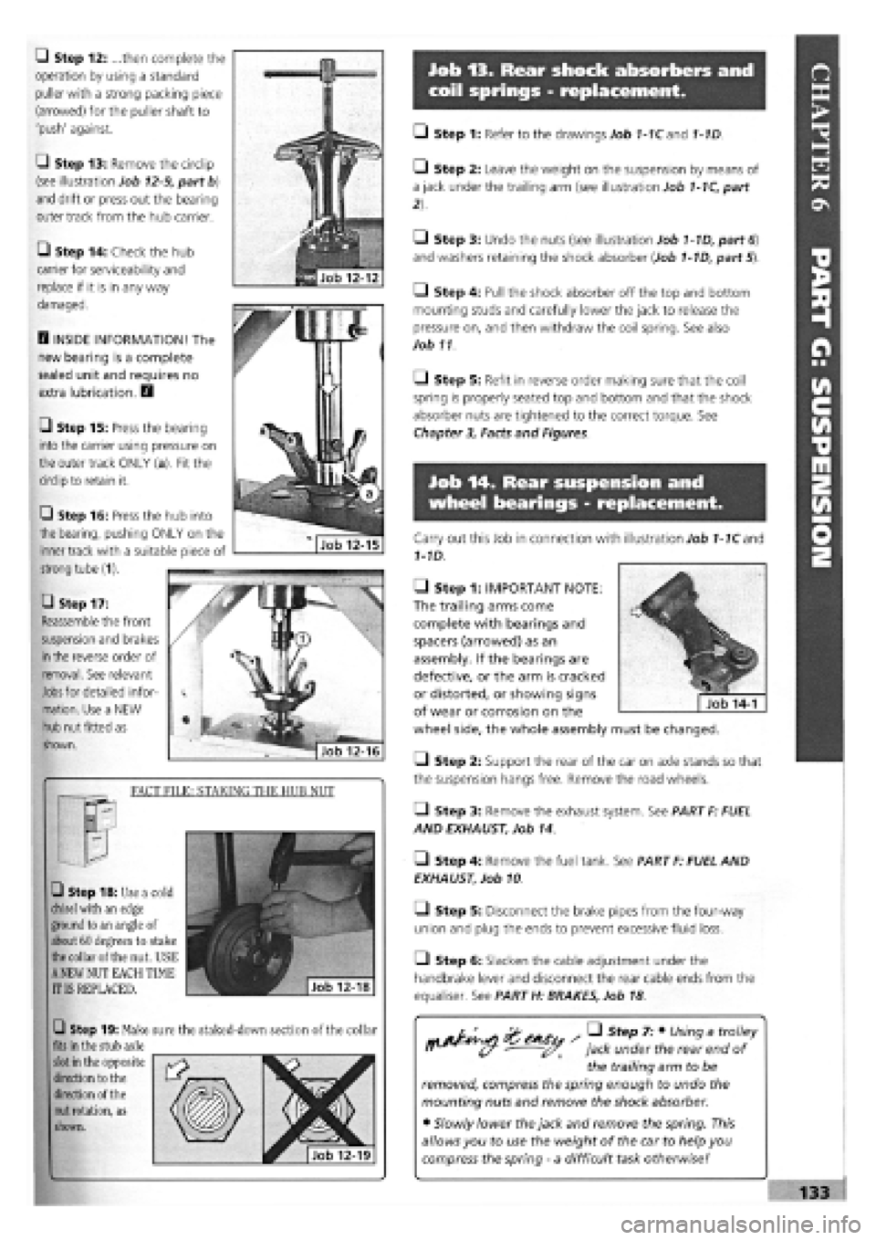
Q Step 12: ...then complete the
operation by using a standard
puller with a strong packing piece
(arrowed) for the puller shaft to
'push' against.
G Step 13: Remove the circlip
(see illustration Job
12-9,
part b)
and drift or press out the bearing
outer track from the hub carrier.
• Step 14: Check the hub
carrier for serviceability and
replace if it is in any way
damaged.
D INSIDE INFORMATION! The
new bearing is a complete
sealed unit and requires no
extra lubrication. D
• Step 15: Press the bearing
into the carrier using pressure on
the outer track ONLY (a). Fit the
circlip to retain it.
• Step 17:
Reassemble the front
suspension and brakes
in
the reverse order of
removal. See relevant
Jobs
for detailed infor-
mation. Use a NEW
hub nut fitted as
shown.
FACT FILE: STAKING THE HUB NUT
• Step 18: Use a cold
chisel
with an edge
ground to an angle of
about 60 degrees to stake
the
collar of the nut. USE
A
NEW NUT EACH TIME
IT IS REPLACED.
Q Step 19: Make sure the staked-down section of the collar
fits
in the stub axle
slot
in the opposite
direction to the
direction of the
nut
rotation, as
shown.
• Step 1: Refer to the drawings Job 1-1Cand 1-1D.
• Step 2: Leave the weight on the suspension by means of
a jack under the trailing arm (see illustration Job
1-1C,
part
• Step 3: Undo the nuts (see illustration Job
1-1D,
part
6)
and washers retaining the shock absorber (Job
1-1D,
part 5).
• Step 4: Pull the shock absorber off the top and bottom
mounting studs and carefully lower the jack to release the
pressure on, and then withdraw the coil spring. See also
Job 11
O Step 5: Refit in reverse order making sure that the coil
spring is properly seated top and bottom and that the shock
absorber nuts are tightened to the correct torque. See
Chapter
3,
Facts and Figures.
Job 14. Rear suspension and
wheel bearings - replacement.
Carry out this Job in connection with illustration Job
1-1C
and
1-1D.
• Step 1: IMPORTANT NOTE:
The trailing arms come
complete with bearings and
spacers (arrowed) as an
assembly. If the bearings are
defective, or the arm is cracked
or distorted, or showing signs
of wear or corrosion on the
wheel side, the whole assembly must be changed.
Q Step 2: Support the rear of the car on axle stands so that
the suspension hangs free. Remove the road wheels.
• Step 3: Remove the exhaust system. See PART F: FUEL
AND EXHAUST, Job 14.
• Step 4: Remove the fuel tank. See PART F: FUEL AND
EXHAUST, Job 10
• Step 5: Disconnect the brake pipes from the four-way
union and plug the ends to prevent excessive fluid loss.
Q Step 6: Slacken the cable adjustment under the
handbrake lever and disconnect the rear cable ends from the
equaliser. See PART H: BRAKES, Job 18
/ • Step 7: • Using a trolley
jack under the rear end of
the trailing arm to be
removed, compress the spring enough to undo the
mounting nuts and remove the shock absorber.
• Slowly lower the jack and remove the spring. This
allows you to use the weight of the car to help you
compress the spring
-
a difficult task otherwise!
Q Step 16: Press the hub into
the bearing, pushing ONLY on the
inner track with a suitable piece of
strong tube (1).
Page 130 of 171
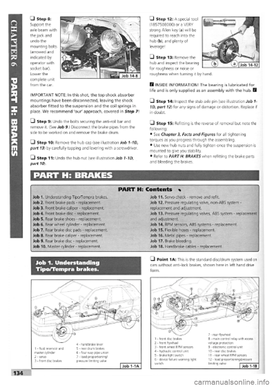
• Step 8:
Support the
axle beam with
the jack and
undo the
mounting bolts
(arrowed and
indicated by
operator with
socket bar).
Lower the
complete unit
from the car.
IMPORTANT NOTE: In this shot, the top shock absorber
mountings have been disconnected, leaving the shock
absorber fitted to the suspension and the coil springs in
place. We recommend 'our' approach, covered in Step 7!
• Step 9: Undo the bolts securing the anti-roll bar and
remove it. (See Job 9.) Disconnect the brake pipes from the
side to be worked on and remove the brake drum.
Q Step 10: Remove the hub cap (see illustration Job 1-1D,
part 13) by carefully tapping and levering with a screwdriver.
• Step 11: Undo the hub nut (see illustration Job 1-1D,
part
10).
PART H: BRAKES
• Step 12: A special tool
(1857508000) or a VERY
strong Allen key (a) will be
required to reach into the
hub (b), and plenty of
leverage!
Q Step 13: Remove the
hub and inspect the bearing
for roughness or noise or
roughness when turning it by hand.
E3 INSIDE INFORMATION! The bearing is lubricated for
life and is only supplied as an assembly with the hub. B
• Step 14: Inspect the stub axle pin (see illustration Job
1-
1D, part
12)
for any signs of damage or distortion. Replace if
in doubt.
Q Step 15: Refitting is the reverse of removal but note the
following:
• See Chapter
3,
Facts and Figures for all tightening
torques as you progress through the assembling.
• Use new hub nuts and fully tighten once the suspension is
mounted to give you stability.
• Refer to PART H: BRAKES when refitting the brake parts
and bleeding the brakes.
PART H: Contents %
Job 1. Understanding Tipo/Tempra brakes.
Job 2. Front brake pads
-
replacement.
Job 3. Front brake caliper
-
replacement.
Job 4. Front brake disc
-
replacement.
Job 5. Rear brake shoes
-
replacement.
Job 6. Rear wheel cylinder
-
replacement.
Job 7. Rear brake disc pads
-
replacement.
Job 8. Rear brake caliper
-
replacement.
Job 9. Rear brake disc
-
replacement.
Job 10. Master cylinder
-
replacement.
Job 11. Servo check
-
remove and refit.
Job 12. Pressure regulating valve, non-ABS system -
replacement and adjustment.
Job 13. Pressure regulating valves, ABS system
-
replacement
and adjustment.
Job 14. RPM sensors, ABS systems
-
replacement.
Job 15. Flexible hoses
-
replacement.
Job 16. Metal pipes
-
replacement.
Job 17. Brake bleeding.
Job 18. Handbrake cables
-
replacement.
Job 1. Understanding
Tipo/Tempra brakes.
• Point
1
A: This is the standard disc/drum system used on
cars without anti-lock brakes, shown here in left hand drive
form.
1 - fluid reservoir and master cylinder 2 - servo 3
-
front disc brakes
4 - handbrake lever 5 - rear drum brakes 6
-
four way pipe union 7 - load proportioning/ pressure limiting valve
Job 1-1A
1 - front disc brakes 2
-
front flywheel 3 - front wheel RPM sensors 4 - hydraulic control unit 5 - brake light switch 6 - device failure warning light switch
7 - rear flywheel 8 - main control relay with excess voltage protection 9 - electronic control unit 10 - rear disc brakes 11 - rear wheel RPM sensors 12 - load proportioning/pressure limiting valve Job
1-1B