FIAT TEMPRA 1988 Service And Repair Manual
Manufacturer: FIAT, Model Year: 1988, Model line: TEMPRA, Model: FIAT TEMPRA 1988Pages: 171, PDF Size: 18.05 MB
Page 111 of 171
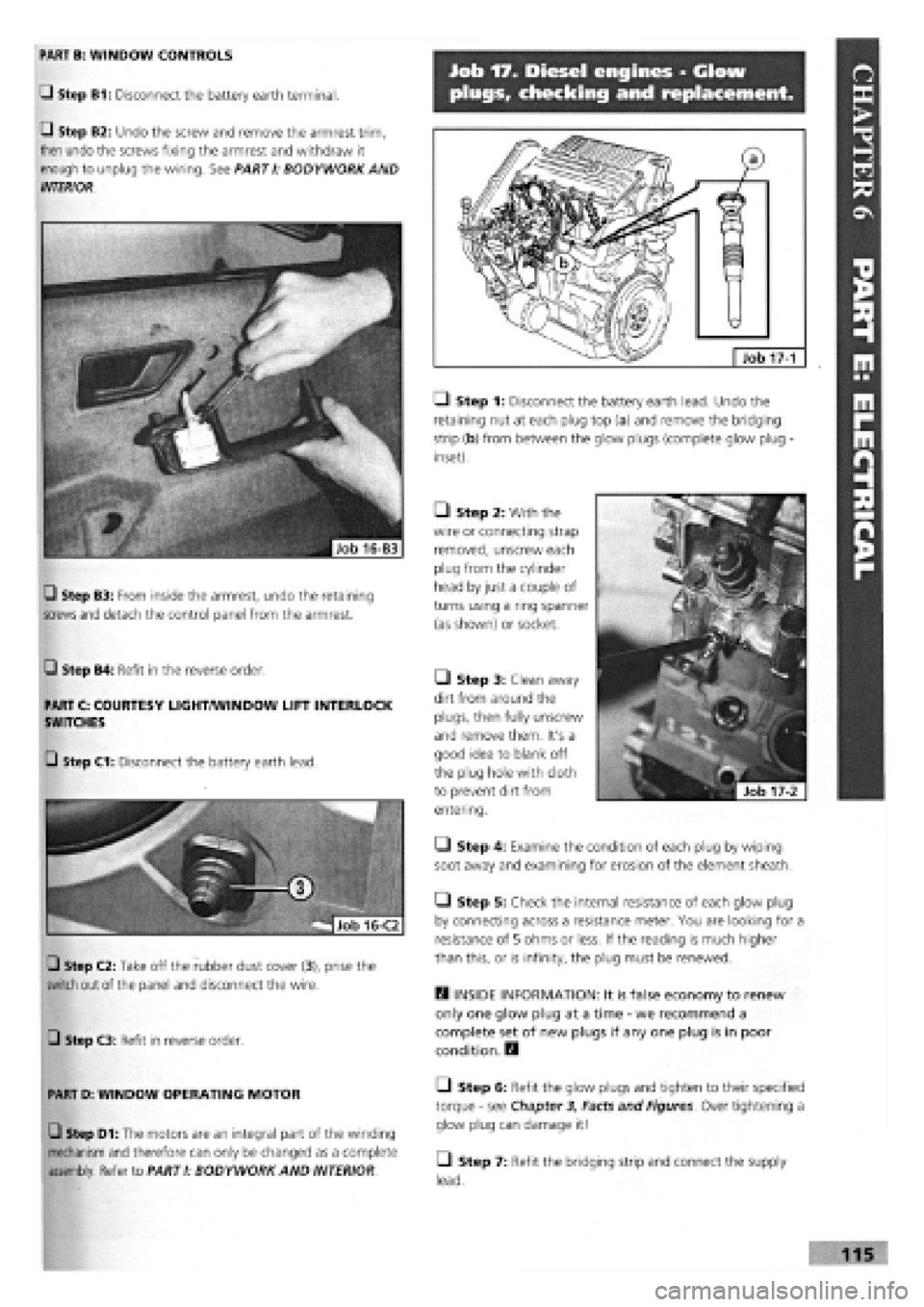
Job 17. Diesel engines - Glow
plugs, checking and replacement.
LI Step 1: Disconnect the battery earth lead. Undo the
retaining nut at each plug top (a) and remove the bridging
strip (b) from between the glow plugs (complete glow plug -
inset).
• Step 2: With the
wire or connecting strap
removed, unscrew each
plug from the cylinder
head by just a couple of
turns using a ring spanner
(as shown) or socket.
H INSIDE INFORMATION: It is false economy to renew
only one glow plug at a time
-
we recommend a
complete set of new plugs if any one plug is in poor
condition. E9
• Step 6: Refit the glow plugs and tighten to their specified
torque
-
see Chapter 3, Facts and Figures. Over tightening a
glow plug can damage it!
• Step 7: Refit the bridging strip and connect the supply
lead.
17-1
PART B: WINDOW CONTROLS
Q Step B1: Disconnect the battery earth terminal.
Q Step B2: Undo the screw and remove the armrest trim,
then undo the screws fixing the armrest and withdraw it
enough to unplug the wiring. See PARTI: BODYWORK AND
INTERIOR.
• Step 3: Clean away
dirt from around the
plugs, then fully unscrew
and remove them. It's a
good idea to blank off
the plug hole with cloth
to prevent dirt from
entering.
• Step 4: Examine the condition of each plug by wiping
soot away and examining for erosion of the element sheath.
• Step 5: Check the internal resistance of each glow plug
by connecting across a resistance meter. You are looking for a
resistance of 5 ohms or less. If the reading is much higher
than this, or is infinity, the plug must be renewed.
Q Step B4: Refit in the reverse order.
PART C: COURTESY LIGHT/WINDOW LIFT INTERLOCK
SWITCHES
Q Step C3: Refit in reverse order.
PART D: WINDOW OPERATING MOTOR
Q Step D1: The motors are an integral part of the winding
mechanism and therefore can only be changed as a complete
assembly. Refer to PART I: BODYWORK AND INTERIOR
Q Step B3: From inside the armrest, undo the retaining
screws and
detach the control panel from the armrest.
G Step C1: Disconnect the battery earth lead.
Q Step C2: Take off the rubber dust cover (3), prise the
switch out of the panel and disconnect the wire.
Page 112 of 171
PART F: FUEL AMD EXHAUST SYSTEMS
PART F: Contents
Job 1. Fuel system types. Job 9. Electric fuel pump, petrol engine (S.P.I.)
-
Job 2. Carburettor
-
removal and refitting. replacement.
Job 3. Petrol injection unit
-
removal and refitting. Job 10. Fuel tank
-
removal and refitting.
Job 4. Accelerator cable, carburettor engines
-
replacement Job 11. Hot air hoses/thermo-valves
-
general.
and adjustment. Job 12. Lambda sensor (S.P.I, engines)
-
replacement.
Job 5. Carburettor choke cable
-
replacement and Job 13. Fuel evaporation system.
adjustment. Job 14. Exhaust system
-
replacement.
Job 6. Accelerator cable, petrol injection engines -Job 15. Turbocharger, diesel engine
-
replacement.
replacement and adjustment. Job 16. Diesel injection pump
-
removal and refitting.
Job 7. Diesel engines. Accelerator cable
-
replacement and Job 17. Diesel injectors
-
remove and refit.
adjustment. Job 18. Bleeding Diesel fuel system.
Job 8. Mechanical fuel pump, petrol engine (carburettored) -
replacement.
Job 1. Fuel system types.
FACT FILE: FUEL INJECTION/ELECTRONIC
IGNITION PRECAUTIONS
OBSERVE THE FOLLOWING PRECAUTIONS
WHEN WORKING ON PETROL-ENGINED
VEHICLES WITH FUEL INJECTION - ELECTRONIC
IGNITION SYSTEMS:
• never start the engine when the electrical terminals are
poorly connected or loose on the battery poles;
• never use a quick battery charger to start the engine;
• never disconnect the battery from the car circuit with the
engine running;
• when charging the battery quickly, first disconnect the
battery from the vehicle circuit;
• if the vehicle is placed in a bodyshop drying oven after
painting at a temperature of more than 80 degrees Celsius,
first remove the injection/ignition ECU;
• never connect or disconnect the ECU multiple connector
with the ignition key in MARCIA position;
• always disconnect battery negative lead before carrying out
electrical welding on vehicle.
Note that some systems contain one memory that is always
active (stand-by memory) and that stores learnt self-adaptive
values. Because this data is lost when the battery is discon-
nected, this operation should be carried out as infrequently as
possible.
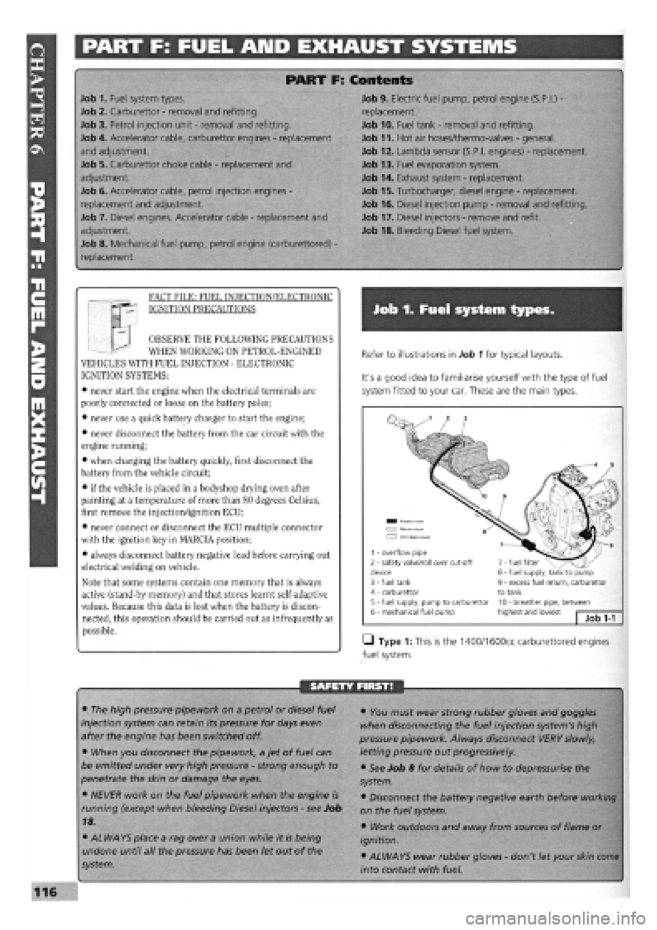
Refer to illustrations in Job 1 for typical layouts.
It's a good idea to familiarise yourself with the type of fuel
system fitted to your car. These are the main types.
• Type 1: This is the 1400/1600cc carburettored engines
fuel system.
SAFETY FIRST!
• The high pressure pipework on a petrol or diesel fuel
injection system can retain its pressure for days even
after the engine has been switched off.
• When you disconnect the pipework, a jet of fuel can
be emitted under very high pressure
-
strong enough to
penetrate the skin or damage the eyes.
• NEVER work on the fuel pipework when the engine is
running (except when bleeding Diesel injectors
-
see Job
18.
• ALWAYS place a rag over a union while it is being
undone until all the pressure has been let out of the
system.
• You must wear strong rubber gloves and goggles
when disconnecting the fuel injection system's high
pressure pipework. Always disconnect VERY slowly,
letting pressure out progressively.
• See Job 8 for details of how to depressurise the
system.
• Disconnect the battery negative earth before working
on the fuel system.
• Work outdoors and away from sources of flame or
ignition.
• ALWAYS wear rubber gloves
-
don't let your skin come
into contact with fuel.
1 - overflow pipe 2 - safety valve/roll over cut-off device 3 - fuel tank 4 - carburettor 5 - fuel supply, pump to carburettor 6 - mechanical fuel pump
7 - fuel filter 8 - fuel supply, tank to pump 9 - excess fuel return, carburettor to tank 10 - breather pipe, between highest and lowest Job
1-1
Page 113 of 171
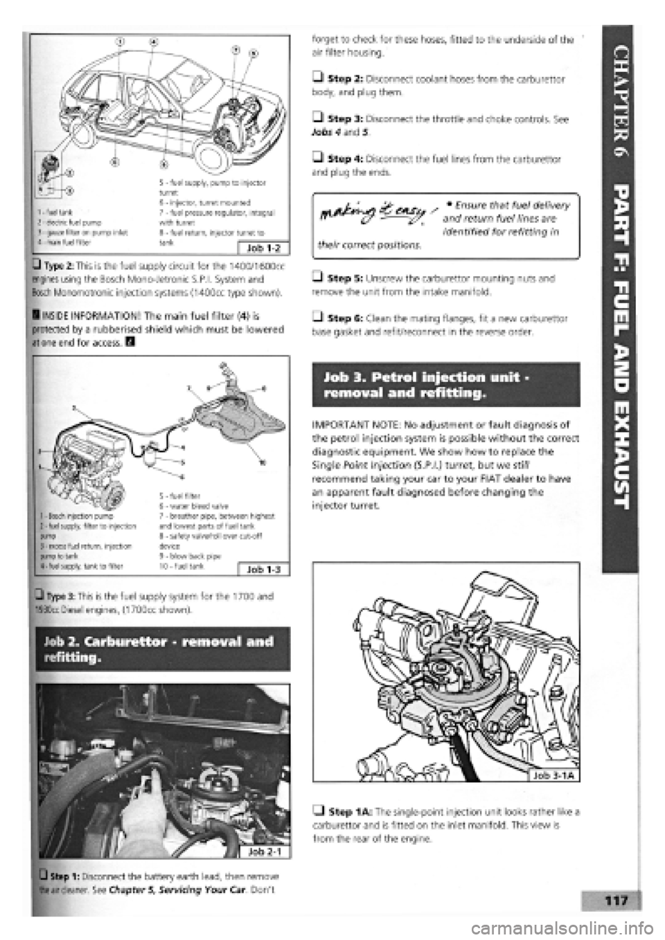
• Type 2: This is the fuel supply circuit for the 1400/1600cc
engines using the Bosch Mono-Jetronic S.P.I. System and
Bosch Monomotronic injection systems (1400cc type shown).
5 - fuel supply, pump to injector turret 6 - injector, turret mounted 7 - fuel pressure regulator, integral with turret 8 - fuel return, injector turret to tank — Job 1-2
1
-
fuel tank 2
-
electric fuel pump 3
-
gauze filter on pump inlet 4
-
main fuel filter
H INSIDE INFORMATION! The main fuel filter (4) is
protected by a rubberised shield which must be lowered
at one end for access. H
5 - fuel filter 6 - water bleed valve 7 - breather pipe, between highest and lowest parts of fuel tank 8 - safety valve/roll over cut-off device 9 - blow back pipe 10 - fuel tank Job 1-3
1
-
Bosch injection pump 2
-
fuel supply, filter to injection pump 3
-
excess fuel return, injection pump to tank 4
-
fuel supply, tank to filter
forget to check for these hoses, fitted to the underside of the
air filter housing.
• Step 2: Disconnect coolant hoses from the carburettor
body, and plug them.
Q Step 3: Disconnect the throttle and choke controls. See
Jobs 4 and 5.
Q Step 4: Disconnect the fuel lines from the carburettor
and plug the ends.
/ • E"sure thf ™ delivery
" (/ and return fuel lines are
identified for refitting in
their correct positions.
• Step 5: Unscrew the carburettor mounting nuts and
remove the unit from the intake manifold.
LI Step 6: Clean the mating flanges, fit a new carburettor
base gasket and refit/reconnect in the reverse order.
Job 3. Petrol injection unit -
removal and refitting.
IMPORTANT NOTE: No adjustment or fault diagnosis of
the petrol injection system is possible without the correct
diagnostic equipment. We show how to replace the
Single Point Injection (S.P.I.) turret, but we still
recommend taking your car to your FIAT dealer to have
an apparent fault diagnosed before changing the
injector turret.
Job 2. Carburettor - removal and
refitting.
Q Type 3: This is the fuel supply system for the 1700 and
1930cc
Diesel engines, (1700cc shown).
Q Step 1: Disconnect the battery earth lead, then remove
the air cleaner.
See Chapter 5, Servicing Your Car. Don't
Q Step 1A: The single-point injection unit looks rather like a
carburettor and is fitted on the inlet manifold. This view is
from the rear of the engine.
Page 114 of 171
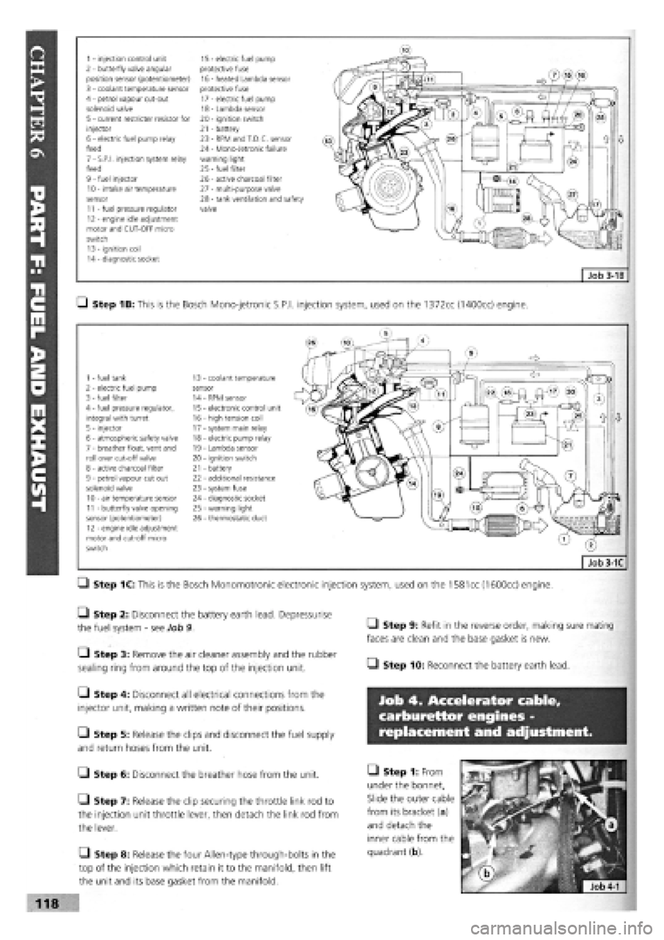
1 - injection control unit 15 - electric fuel pump 2 - butterfly valve angular protective fuse position sensor (potentiometer) 16 - heated Lambda sensor 3 - coolant temperature sensor protective fuse 4 - petrol vapour cut-out 17 - electric fuel pump solenoid valve 18 - Lambda sensor 5 - current restricter resistor for 20 - ignition switch injector 21 - battery 6 - electric fuel pump relay 23 - RPM and T.D.C. sensor feed 24 - Mono-Jetronic failure 7 - S.P.I, injection system relay warning light feed 25
-
fuel filter 9 - fuel injector 26 - active charcoal filter 10 - intake air temperature 27 - multi-purpose valve sensor 28 - tank ventilation and safety 11 - fuel pressure regulator valve 12 - engine idle adjustment motor and CUT-OFF micro switch 13 - ignition coil 14 - diagnostic socket
Q Step 1B: This is the Bosch Mono-jetronic S.P.I, injection system, used on the 1372cc (1400cc) engine.
1 - fuel tank 13 coolant temperature 2 - electric fuel pump sensor 3 - fuel filter 14 RPM sensor 4 - fuel pressure regulator, 15 electronic control unit integral with turret 16 - high tension coil 5 - injector 17 - system main relay 6 - atmospheric safety valve 18 - electric pump relay 7 - breather float, vent and 19 - Lambda sensor roll over cut-off valve 20 - ignition switch 8 - active charcoal filter 21 - battery 9 - petrol vapour cut out 22 - additional resistance solenoid valve 23 - system fuse 10 - air temperature sensor 24 - diagnostic socket 11 - butterfly valve opening 25 - warning light sensor (potentiometer) 26 - thermostatic duct 12 - engine idle adjustment motor and cut-off micro switch
Q Step 1C: This is the Bosch Monomotronic electronic injection system, used on the
1581
cc (1600cc) engine.
• Step 2: Disconnect the battery earth lead. Depressurise
the fuel system
-
see Job 9.
• Step 3: Remove the air cleaner assembly and the rubber
sealing ring from around the top of the injection unit.
Q Step 4: Disconnect all electrical connections from the
injector unit, making a written note of their positions.
Q Step 5: Release the clips and disconnect the fuel supply
and return hoses from the unit.
G Step 6: Disconnect the breather hose from the unit.
• Step 7: Release the clip securing the throttle link rod to
the injection unit throttle lever, then detach the link rod from
the lever.
Q Step 8: Release the four Allen-type through-bolts in the
top of the injection which retain it to the manifold, then lift
the unit and its base gasket from the manifold.
• Step 9: Refit in the reverse order, making sure mating
faces are clean and the base gasket is new.
• Step 10: Reconnect the battery earth lead.
Job 4. Accelerator cable,
carburettor engines -
replacement and adjustment.
• Step 1: From
under the bonnet,
Slide the outer cable
from its bracket (a)
and detach the
inner cable from the
quadrant (b).
118
Page 115 of 171
Job 6. Accelerator cable, petrol
injection engines - replacement
and adjustment.
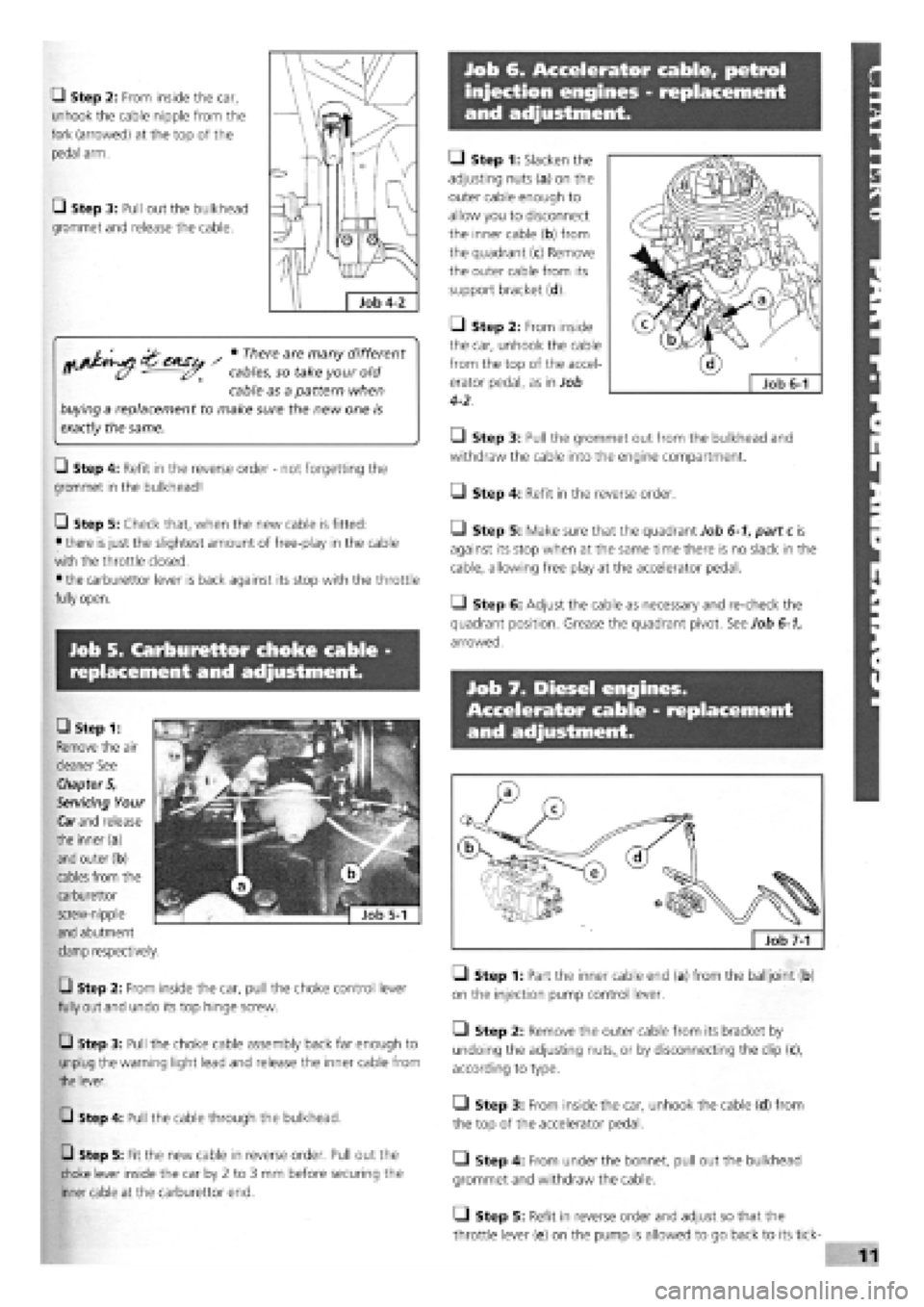
Q Step 2: From inside the car,
unhook the cable nipple from the
fork (arrowed) at the top of the
pedal arm.
• Step 3: Pull out the bulkhead
grommet and release the cable.
^ • There are many different
cables, so take your old
cable as a pattern when
buying a replacement to make sure the new one is
exactly
the same.
Q Step 4: Refit in the reverse order
-
not forgetting the
grommet in the bulkhead!
Q Step 5: Check that, when the new cable is fitted:
• there
is
just the slightest amount of free-play in the cable
with the throttle closed.
• the carburettor lever is back against its stop with the throttle
fully open.
• Step 1: Slacken the
adjusting nuts (a) on the
outer cable enough to
allow you to disconnect
the inner cable (b) from
the quadrant (c) Remove
the outer cable from its
support bracket (d).
Q Step 2: From inside
the car, unhook the cable
from the top of the accel-
erator pedal, as in Job
4-2.
• Step 3: Pull the grommet out from the bulkhead and
withdraw the cable into the engine compartment.
O Step 4: Refit in the reverse order.
• Step 5: Make sure that the quadrant Job 6-1, part c is
against its stop when at the same time there is no slack in the
cable, allowing free play at the accelerator pedal.
• Step 6: Adjust the cable as necessary and re-check the
quadrant position. Grease the quadrant pivot. See Job 6-1,
arrowed.
Job 7. Diesel engines.
Accelerator cable - replacement
and adjustment.
Job 5. Carburettor choke cable -
replacement and adjustment.
Q Step 2: From inside the car, pull the choke control lever
fully out and undo its top hinge screw.
Q Step 3: Pull the choke cable assembly back far enough to
unplug the warning light lead and release the inner cable from
the lever.
Q Step 4: Pull the cable through the bulkhead.
Q Step 5: Fit the new cable in reverse order. Pull out the
choke lever inside the car by 2 to 3 mm before securing the
inner cable at the carburettor end.
Q Step 1: Part the inner cable end (a) from the balljoint (b)
on the injection pump control lever.
• Step 2: Remove the outer cable from its bracket by
undoing the adjusting
nuts,,
or by disconnecting the clip (c),
according to type.
• Step 3: From inside the car, unhook the cable (d) from
the top of the accelerator pedal.
• Step 4: From under the bonnet, pull out the bulkhead
grommet and withdraw the cable.
Q Step 5: Refit in reverse order and adjust so that the
throttle lever (e) on the pump is allowed to go back to its tick-
CD Step 1:
Remove the air
cleaner See
Chapter 5,
Servicing Your
Car
and
release
the inner(a)
and outer (b)
cables from the
carburettor
screw-nipple
and abutment
clamp respectively.
Page 116 of 171
over stop and will also reach its 'maximum speed' stop with
the pedal fully depressed.
Job 8. Mechanical fuel pump,
petrol engine (carburettored) -
replacement.
O Step 1: Disconnect the battery earth lead.
• Step 2: Find the pump on the forward facing side of the
cylinder block near the timing cover end. Disconnect the two
fuel lines from the pump and plug the ends, (labelling them
for correct refitment).
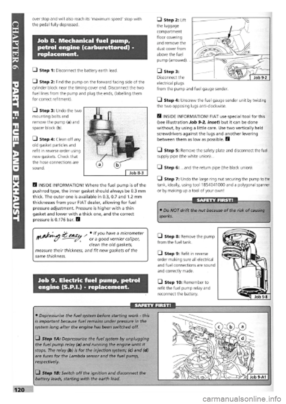
• Step 3: Undo the two
mounting bolts and
remove the pump (a) and
spacer block (b).
• Step 4: Clean off any
old gasket particles and
refit in reverse order using
new gaskets. Check that
the hose connections are
sound.
D INSIDE INFORMATION! Where the fuel pump is of the
pushrod type, the inner gasket should always be 0.3 mm
thick. The outer one is available in 0.3, 0.7 and 1.2 mm
thicknesses from your FIAT dealer, allowing for fuel
pressure adjustment. Pressure is higher with a thin
gasket and lower with a thick one, and the correct
pressure is 0.176 bar. Q
/ # lfyou h"ve a m/cromefer
ff (y - or a good vernier caliper,
clean the old gaskets,
measure their thickness, and fit new gaskets of the
same thickness.
Job 9. Electric fuel pump, petrol
engine (S.P.I.) - replacement.
• Step 2: Lift
the luggage
compartment
floor covering
and remove the
dust cover from
above the fuel
pump (arrowed). .
• Step 3:
Disconnect the
electrical plugs
from the pump and fuel gauge sender.
• Step 4: Unscrew the fuel gauge sender unit by twisting
the two opposing lugs anti-clockwise.
D INSIDE INFORMATION! FIAT use special tool for this
(see illustration Job
9-2,
inset) but it can be done
without, by using a little care. Use two vertically held
screwdrivers against the lugs and another levering
between them as low as possible. H
Q Step 5: Remove the safety plate and disconnect the fuel
supply pipe (the white union)...
Q Step 6: ...and the return pipe (the black union).
1-1 Step 7: Undo the large ring nut securing the pump to the
tank, ideally, using tool 1854041000 and a polygonal spanner
or by making up a tool of your own!
SAFETY FIRST!
• Do NOT drift the nut because of the risk of
causing
sparks.
Q Step 8: Remove the pump
from the fuel tank.
Q Step 9: Refit in reverse
order making sure all electrical
and fuel connections are sound
and correctly made.
• Step 10: Remember to
refit the fuel pump relay and
reconnect the battery.
SAFETY FIRST!
• Depressurise the fuel system before starting work
-
this
is important because fuel remains under pressure in the
system long after the engine has been switched off.
• Step 1A: Depressurise the fuel system by unplugging
the fuel pump relay (a) and running the engine until it
stops. The relay (b) is for the injection system; (c) and (d)
are fuses for the Lambda sensor and the fuel pump,
respectively.
• Step 1B: Switch off the ignition and disconnect the
battery leads, starting with the earth lead.
Page 117 of 171
Job 10. Fuel tank - removal and
refitting.
Job 11. Hot air hoses/thermo-
valves - general.
SAFETY FIRST!
Job 12. Lambda sensor
(S.P.I, engines) - replacement.
• We recommend that you carry out all of this work
out of
doors.
I
IMPORTANT NOTE:
• Read Chapter 1, Safety First! before carrying out
this
work!
• Plan ahead! Run the fuel in the tank as low as possible
before you start this job.
Q Step 1: Disconnect the battery leads starting with the
earth lead.
• Step 2: Syphon any remaining fuel from the tank and
into a suitable closed container.
Q Step 3: Disconnect the fuel sender wiring and any fuel
hoses
from within the boot (model-dependent
-
see Job 9 and
PARTE: ELECTRICAL AND INSTRUMENTS, Job 14).
• Step 4: Disconnect the filler and breather hoses from the
tank,
working from underneath the car.
a - Lambda sensor b - connector to ECU c - sensor heater power supply Job 12-2
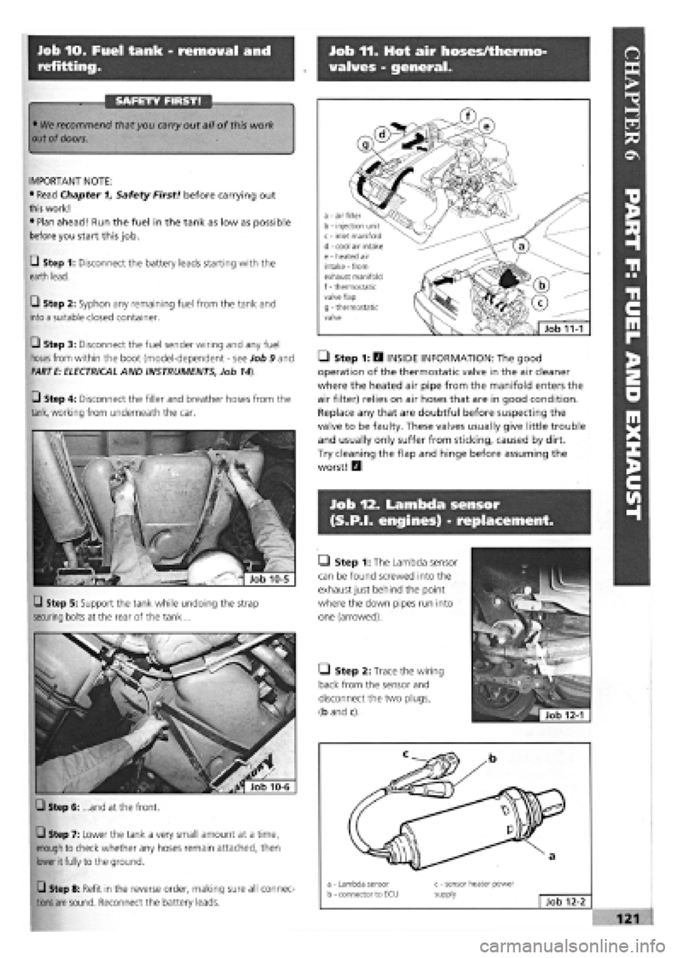
Q Step 5: Support the tank while undoing the strap
securing bolts at the rear of the tank...
Q Step 6: ...and at the front.
Q Step 7: Lower the tank a very small amount at a time,
enough to check whether any hoses remain attached, then
lower it fully to the ground.
Q Step 8: Refit in the reverse order, making sure all connec-
tions are
sound. Reconnect the battery leads.
• Step 1: H INSIDE INFORMATION: The good
operation of the thermostatic valve in the air cleaner
where the heated air pipe from the manifold enters the
air filter) relies on air hoses that are in good condition.
Replace any that are doubtful before suspecting the
valve to be faulty. These valves usually give little trouble
and usually only suffer from sticking, caused by dirt.
Try cleaning the flap and hinge before assuming the
worst! Q
• Step 1: The Lambda sensor
can be found screwed into the
exhaust just behind the point
where the down pipes run into
one (arrowed).
Q Step 2: Trace the wiring
back from the sensor and
disconnect the two plugs,
(b and c).
a - air filter b - injection unit c - inlet manifold d - cool air intake e - heated air intake - from exhaust manifold f
-
thermostatic valve flap g - thermostatic valve
Job 11-1
Page 118 of 171
Job 14. Exhaust system -
replacement.
FACT FILE: LAMBDA SENSOR
• The Lambda sensor is very fragile and
should not be knocked or dropped.
• We recommend that a new one is fitted
only by your FIAT dealer, who can test the
old one to see whether it is working properly.
• No cleaners should be used on the sensor.
Q Step 3: Before refitting, check that the sensor sealing ring
is in good condition, and lubricate the thread of the sensor
with a high-temperature anti-seize compound.
Job 13. Fuel evaporation system.
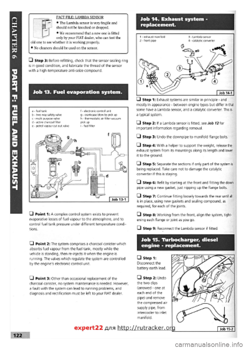
a - fuel tank b - two way safety valve c - multi purpose valve d
-
active charcoal filter e - petrol vapour cut out valve
f - electronic control unit g - crankcase blow by pick up h - thermostatic air filter vacuum pick up i - fuel filter
• Point 1: A complex control system exists to prevent
evaporative losses of fuel vapour to the atmosphere, and to
control fuel tank pressure under different temperature condi-
tions.
—) Step 1: Exhaust systems are similar in principle
-
and
mostly in appearance
-
between engine types but differ in that
some have a Lambda sensor, and a catalytic converter. This is
a typical system.
• Step 2: If a Lambda sensor is fitted, see Job
12
for
important information regarding removal.
• Step 3: Undo the downpipe to manifold flange bolts.
• Step 4: With a helper to support the weight, release the
exhaust system from its mountings along its length and lower
it to the ground.
O Step 5: Separate the sections if only part of the system is
being replaced. Take care not to damage the catalytic
converter if this is staying.
• Step 6: Refit by starting at the front and fitting the down
pipe using a new gasket, just nipping up the flange bolts.
• Step 7: Continue fitting loosely towards the rear until all
is in place, using new gaskets and sealing compound, as
required, for each of the joints.
• Step 8: Working from the front, align the system, tight-
ening each flange or joint as you go.
• Step 9: Reconnect the Lambda sensor if fitted.
• Point 2: The system comprises a charcoal canister which
absorbs fuel vapour from the fuel tank, mostly while the
vehicle is standing, then re-injects it when the engine is
running. The valves which regulate the system are controlled
by the engine's electronic control unit.
• Point 3: Other than occasional replacement of the
charcoal canister, no system maintenance is needed. However,
a fault with the system can lead to running problems, and
diagnosis and rectification must be left to your FIAT dealer.
Job 15. Tlurbocharger, diesel
engine - replacement.
• Step 1:
Disconnect the
battery earth lead.
• Step 2: Undo
the two clips
(arrowed
-
one at
each end of the
pipe) and remove
the compressed air
supply pipe, from
intercooler to inlet
manifold.
expert22 fl/i* http://rutracker.or
Page 119 of 171
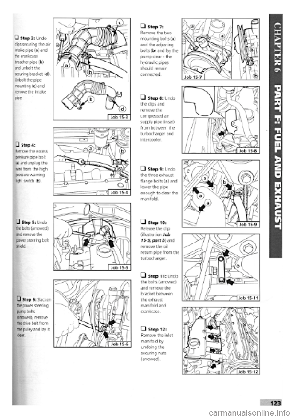
• Step 3: Undo
clips securing the air
intake pipe (a) and
the crankcase
breather pipe (b)
and unbolt the
securing bracket (d).
Unbolt the pipe
mounting (c) and
remove the intake
pipe.
• Step 4:
Remove the excess
pressure pipe bolt
(a)
and
unplug the
wire from
the high
pressure warning
light
switch (b).
• Step 5: Undo
the
bolts (arrowed)
and
remove the
power steering belt
shield.
• Step 6: Slacken
the
power steering
pump
bolts
(arrowed), remove
the
drive belt from
the
pulley and lay it
clear.
7"
e
L Job 15-5
• Step 7:
Remove the two
mounting bolts (a)
and the adjusting
bolts (b) and lay the
pump clear
-
the
hydraulic pipes
should remain
connected.
• Step 8: Undo
the clips and
remove the
compressed air
supply pipe (inset)
from between the
turbocharger and
intercooler.
• Step 9: Undo
the three exhaust
flange bolts (a) and
lower the pipe
enough to clear the
manifold.
• Step 10:
Release the clip
(illustration Job
15-9, part fa) and
remove the oil
return pipe from the
turbocharger.
• Step 11: Undo
the bolts (arrowed)
and remove the
bracket between
the exhaust
manifold and
crankcase.
• Step 12:
Remove the inlet
manifold by
undoing the
securing nuts
(arrowed).
O)
T'
123
Page 120 of 171
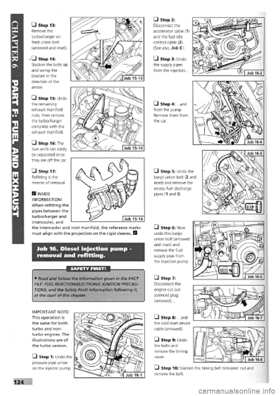
• Step 13:
Remove the
turbocharger oil
feed union bolt
(arrowed and inset).
Step 14:
Slacken the bolts (a)
and swing the
bracket in the
direction of the
arrow.
• Step 15: Undo
the remaining
exhaust manifold
nuts, then remove
the turbocharger
complete with the
exhaust manifold.
• Step 16: The
two units can easily
be separated once
they are off the car.
• Step 17:
Refitting is the
reverse of removal.
• Step 2:
Disconnect the
accelerator cable (1)
and the fast idle
control cable (2).
(See also, Job 6.)
• Step 3: Undo
the supply pipes
from the injectors...
Q Step 4: ...and
from the pump.
Remove them from
the car.
• Step 5: Undo the
banjo union bolt (2 and
inset) and remove the
excess fuel discharge
pipes
(1
and 3).
Job 16. Diesel injection pump -
removal and refitting.
SAFETY FIRST!
• Read and follow the information given in the FACT
FILE: FUEL INJECTION/ELECTRONIC IGNITION PRECAU-
TIONS, and the Safety First! information following it,
at the start of this chapter.
• Step 10: Slacken the timing belt tensioner nut and
remove the belt.
• Step 6: Now
undo this banjo
union bolt (arrowed
and inset) and
remove the fuel
supply pipe from
the injection pump.
• Step 7:
Disconnect the
engine cut out
solenoid plug
(arrowed)...
• Step 8: ...and
the cold start device
cable (arrowed).
• Step 9: Undo
the bolts and
remove the timing
cover.
IMPORTANT NOTE:
This operation is
the same for both
turbo and non-
turbo engines. The
illustrations are of
the turbo version.
• Step 1: Undo the
pressure pipe union
on the injector pump.
• INSIDE
INFORMATION!
When refitting the
pipes between the
turbocharger and
intercooler, and
the intercooler and inlet manifold, the reference marks
must align with the projection on the rigid sleeves. E3
Job 16-6