GEELY CK 2008 Workshop Manual
Manufacturer: GEELY, Model Year: 2008, Model line: CK, Model: GEELY CK 2008Pages: 392, PDF Size: 38.86 MB
Page 301 of 392

294III. HCU Replacement1. Depress the retaining clip on the union joint side
and remove the cylinder motor wire harness.
2. Remove the 4 screws as shown in the figure, the
removed old screw can not be reused.
3. Separate the HCU from the ECU.
4. Install the new HCU to the ECU.
5. Use new screw to attach the ECU to the HCU,
tighten the torque: 3+1Nm.
6. Connect the motor wire harness, be careful that
the retaining clip shall be in place.IV. ECU Replacement1. Depress the retaining clip on the union joint side and remove the
wire harness.
2. Remove the 4 screws as shown in the figure and discard them
3. Remove the HCU from the ECU.
4. Install the new ECU to the HCU.
5. Use the new screw to attach the ECU to the HCU, tighten the
torque3+1Nm.
6. Connect the motor wire harness, be careful that the retaining clip
shall be in place.
Page 302 of 392

295V. ABS Assembly ReinstallationNote: the plug of the ABS assembly hydraulic outlet can only be removed after the brake pipe is
installed, lest the foreign object will enter the brake system.1. Install the ABS assembly to the bracket, tighten the torque: 20+4Nm.
2. Remove the plug of the hydraulic outlet, installed the brake pipe. Make sure that the brake pipe is
correctly installed.
3. Install the brake pipe connected to the master cylinder.
4. The brake pipe torque is 12+4Nm (M10 x 1) and 15+3Nm (M12 x 1).
5. Fill the new brake fluid into the reservoir until the liquid level reach the MAX and bleed it as specified.
6. With the ignition switch ON, ABS Warning Light must goes on for 1.7 seconds then goes off.
7. Clear the DTC memory, check if there is DTC again.
8. Drive the vehicle to confirm the ABS function (you must feel that the pedal rebound).VI. ECU ProgramNote: when replacing the HECU or ECU, you shall program the new ECU, otherwise the ABS
Warning Light flashes and the system can not operate normally.Use the scan meter to program the ECU based on the following procedure:Connect the scan meter with the diagnostic interfaceSelect function 07, Press OK button to confirmEnter code 01901 and Press OK button to confirmSelect function 07, Press OK button to confirm, quit the diagnosticEnd
Page 303 of 392

296VII. Fill the liquid and bleedAfter replacing the HECU, bleed the second HECU circuit in addition to the filling and bleeding of the regular
brake system. Use the scan meter to perform the following procedure:Fill the fluid and bleed based on the regular brake system
until there is no air bubble in the transparent hoseConnect the scan meter with the diagnostic interfaceSelect function 04, Press OK button to confirmDepress the brake pedal and keep the hydraulic cylinder pushrod reboundRelease the brake pedal, loosen the left and right brake caliperbleeder screw, press "" buttonDepress the brake pedal 10 times, tighten the left and right
brake caliper bleeder screw, press "" buttonRepeat the above I II III steps 7 times and press "" buttonThe screen display the end of the bleed, press
"" button to return to "function selection" menuSelect function 06, Press OK button to confirm, quit the
diagnostic modeEnd →↑
↑
↑
Page 304 of 392

297Part IV Air Conditioner and Inside &
Outside TrimChapter 1 A/C SystemA/C system consists of refrigerating and heating system. The Refrigeration system mainly comprises
compressor, condenser and evaporator. The refrigerant circulation absorbs the heat in the air and discharge
the vapour to lower the temperature in and dehumidify the compartment. The heating system is mainly
composed of heat exchanger and heater. It heats the compartment throught the heat exchanger by heating
the air with the heat from the cooling water in the engine. The control of air temperature, humidity and
velocity of flow in the compartment is realized by independent or joint working of heating and Refrigeration
system.Section 1 The Structure & Working Principle of Refrigeration SystemThe structure of Refrigeration system is shown in Figure 1.
Figure 1 The Structure and Working Principle of Refrigeration System
1. Compressor 2. Condenser 3.Receiver/Drier
4.Pressure Relief Valve 5.Expansion Valve 6.Evaporator 7.Blower
Refrigeration system uses vapor compressing refrigeration cycle, comprising the compressor, condenser,
pressure relief valve, evaporator, blower , expansion valve, receiver/drier and pipe.
It's working principle is as shown in the Figure 1. The compressor (1) sucks in the refrigerant gas in the
Page 305 of 392

298evaporator (6) via the expansion valve (5) for compression and generates high temperature and pressure
vapor which then is cooled into liquid through the condenser (2) and dried in the receiver/drier (3), then
restrict the expansion valve and enable certain amount of refrigerant liquid to be vapored into low tempera-
ture and pressure vapor in the evaporator, meanwhile, absorb large amount of heat and perform heat ex-
change with the air sucked in by the blower, then distribute the cooled air to the vehicle compartments. Cycle
the operation until the compartments gets the desired temperature.
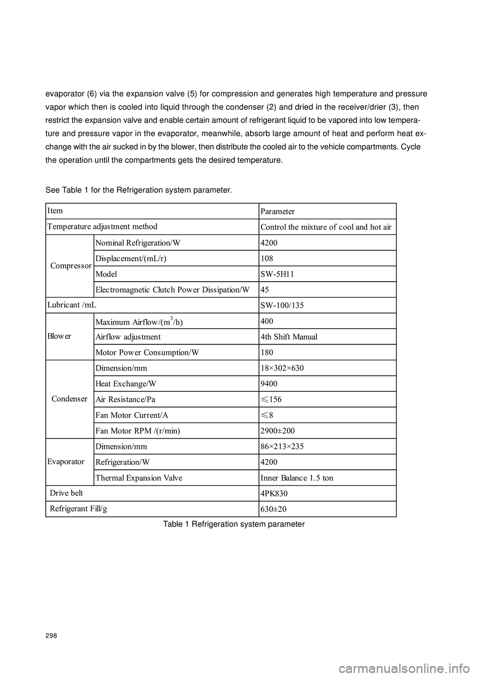
See Table 1 for the Refrigeration system parameter.
Table 1 Refrigeration system parameterParameter
Control the mixture of c ool and hot air
N o m in a l R e f r ig e r a t io n / W 4 2 0 0
Displac ement/(mL/r) 108
Model SW-5H11
Elec tromagnetic Clutc h Pow er Diss ipation/W 45
SW-100/135
Maximum Airflow /(m3/h)400
Airflow adjustment 4th Shift Manual
Motor Pow er Consumption/W 180
Dimension/mm 18×302×630
Heat Exchange/W 9400
Air Resistance/Pa
≤156
Fan Motor Current/A
≤8
Fan Motor RPM /(r/min) 2900±200
Dimension/mm 86×213×235
Refrigeration/W 4200
Thermal Expansion Valve Inner Balanc e 1.5 ton
4PK830
630±20 Re f r ig e r a n t F ill/ g Blo w e r
Condens er
Evapor ator
D r iv e b e lt Item
Temperature adjustment method
Compr es s or
Lubric ant /mL
Page 306 of 392

299Section 2 Heating SystemHeating system uses mixed temperature adjustment which controls both cold and hot air and is featured in
outstanding temperature adjustment performance. The cold and hot air can be completely mixed at each
outlet and achieve continuous temperature adjustment. The air duct arrangement on the instrument panel is
shown in Figure 2. The air flow channel system is shown in Figure 3.I. Heating System Parameter and StructureHeating system uses water heating structure which uses the engine coolant as the heat source, leads the the
coolant into the heating radiator installed in the vehicle compartment and has the interior or exterior air blow
across the radiator with the blower to increase its temperature. The system consists of the blower assembly,
heating control assembly and heater assembly.Figure 2 Heating Duct ArrangementInside and Outside Air Switch Door Outdoor AirIndoor AirDefoggerIntermidiate outletHeaterBlower MotorEvaporatorAir Mix DoorHeating RadiatorFigure 3 Air Flow Channel System Illustration
Page 307 of 392

3001. Heating System Parameter
Heating system radiating power, blower fan diameter, power dissipation and heater radiator dimension are
show in the table 2.
Table2
Heating System Parameter
2. Blower
Blower is located at the lower part of the goods
compartment. The door inside the blower case is con-
trolled by the servomotor. The exchange of the air in-
side and outside the door can be achieved by adjusting
the door to import the outdoor air and recirculate the
indoor air.
Blower motor uses Permenant magnet DC motor with multple blade fan. In addition, there are a set of
resistance on the blower which adjust the fan, called as adjusting resistor. Blower provides wind supply not
only to the heating radiator, but also to the evaporator in the refrigeration system.
3. A/C Control Mechanism
A/C control mechanism is located in the middle of the instrument panel. All adjustment except the A/C switch
and inside and outside circulation switch are made by rotating the control knob. The A/C control panel is
shown in Figure 4.
1Temperature adjustment control knob: control the mix ratio of the cold and hot air by adjusting the air mix
door, use the control knob to achieve continuous temperature adjustment.
2Outlet control knob: use 4 ranges, different types of air flow adjustment available.
3Inside and outside circulation switch: It can toggles between the introduction of outdoor air and recirculation
of the indoor air. (press the switch for inside circulation)
4Blower switch: when the plum blossom range is closed, the remaining four ranges are used to adjust the
air flow.
5A/C switch: as the switch of the refrigeration system, use press-button with built-in A/C indicator.Dissipation Power/W 4000
Air Flow/(m3/h)280
Power Consumption /W 180
Fan Diameter/mm 140
Overall Radiator Dimension 159.4mm×140mm×49mm Figure 4 A/C Control Panel
Page 308 of 392

301 4. Heater
Figure 5 Heater Door Control Diagram
The heater comprises the heater radiator (heat exchanger), the plastic case forming the air duct, connecting
rods adjusting different air ducts and the door. The two groups of combination doors in the heater case are
connected to the heating control mechanism by the cable. The first group is the two couple action doors
adjusting the air mix ratio that are located in the outlet and inlet each; the second group comprises 4 doors
controlling the air outlet vents, where the upper center one controls the front outlet vent, each of the upper
left and right sides controls a defogger outlet vent and lower foot outlet vent. Figure 5 shows the working
principle of temperature adjustment door. The d) , c) , e) , f) in the figure indicate the outlet air flow direction
as the result of the adjustment of the control knob in the heating control mechanism panel.Hot Wind LocationCold Wind LocationLinkageRadiator CoreRadiator CoreTemperature Adjustment
Door Working PrincipleFoot OutletTo Front OutletTo DefrosterRadiator CoreTo Front OutletRadiator CoreFoot OutletFoot OutletTo Defroster
Page 309 of 392

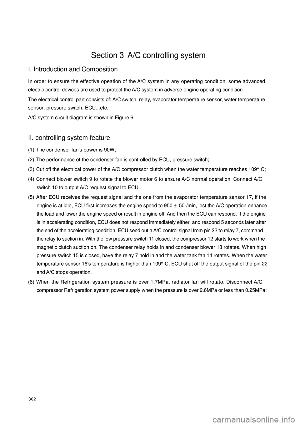
302Section 3 A/C controlling systemI. Introduction and CompositionIn order to ensure the effective opeation of the A/C system in any operating condition, some advanced
electric control devices are used to protect the A/C system in adverse engine operating condition.
The electrical control part consists of: A/C switch, relay, evaporator temperature sensor, water temperature
sensor, pressure switch, ECU...etc.
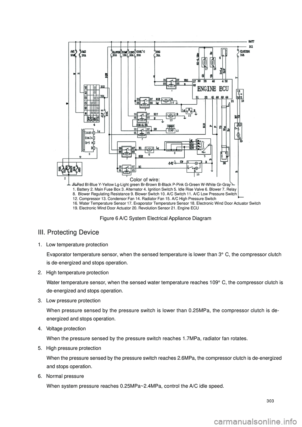
A/C system circuit diagram is shown in Figure 6.II. controlling system feature(1) The condenser fan's power is 90W;
(2) The performance of the condenser fan is controlled by ECU, pressure switch;
(3) Cut off the electrical power of the A/C compressor clutch when the water temperature reaches 109°C;
(4) Connect blower switch 9 to rotate the blower motor 6 to ensure A/C normal operation. Connect A/C
switch 10 to output A/C request signal to ECU.
(5) After ECU receives the request signal and the one from the evaporator temperature sensor 17, if the
engine is at idle, ECU first increases the engine speed to 950 ± 50r/min, lest the A/C operation enhance
the load and lower the engine speed or result in engine off. And then the ECU can respond. If the engine
is in accelerating condition, ECU does not respond immediately either, and respond 5 seconds later after
the end of the accelerating condition. ECU send out a A/C control signal from pin 22 to relay 7, command
the relay to suction in. With the low pressure switch 11 closed, the compressor 12 starts to work when the
magnetic clutch suction on. The condenser relay holds in and condenser blower 13 rotates. When high
pressure switch 15 is closed, have the relay 7 hold in and the water tank fan 14 rotates. When the water
temperature sensor 16's temperature is higher than 109°C, ECU shut off the output signal of the pin 22
and A/C stops operation.
(6) When the Refrigeration system pressure is over 1.7MPa, radiator fan will rotato. Disconnect A/C
compressor Refrigeration system power supply when the pressure is over 2.6MPa or less than 0.25MPa;
Page 310 of 392

303Figure 6 A/C System Electrical Appliance DiagramIII. Protecting Device1. Low temperature protection
Evaporator temperature sensor, when the sensed temperature is lower than 3°C, the compressor clutch
is de-energized and stops operation.
2. High temperature protection
Water temperature sensor, when the sensed water temperature reaches 109°C, the compressor clutch is
de-energized and stops operation.
3. Low pressure protection
When pressure sensed by the pressure switch is lower than 0.25MPa, the compressor clutch is de-
energized and stops operation.
4. Voltage protection
When the pressure sensed by the pressure switch reaches 1.7MPa, radiator fan rotates.
5. High pressure protection
When the pressure sensed by the pressure switch reaches 2.6MPa, the compressor clutch is de-energized
and stops operation.
6. Normal pressure
When system pressure reaches 0.25MPa~2.4MPa, control the A/C idle speed. Color of wire:R-Red Bl-Blue Y-Yellow Lg-Light green Br-Brown B-Black P-Pink G-Green W-White Gr-Gray
1. Battery 2. Main Fuse Box 3. Alternator 4. Ignition Switch 5. Idle Rise Valve 6. Blower 7. Relay
8. Blower Regulating Resistance 9. Blower Switch 10. A/C Switch 11. A/C Low Pressure Switch
12. Compressor 13. Condensor Fan 14. Radiator Fan 15. A/C High Pressure Switch
16. Water Temperature Sensor 17. Evaporator Temperature Sensor 18. Electronic Wind Door Actuator Switch
19. Electronic Wind Door Actuator 20. Revolution Sensor 21. Engine ECU