GEELY CK 2008 Workshop Manual
Manufacturer: GEELY, Model Year: 2008, Model line: CK, Model: GEELY CK 2008Pages: 392, PDF Size: 38.86 MB
Page 321 of 392

314Have a focus inspection on the following area:
a. Each pipe union joint and valve connection.
b. All hose, especially near the pipe union.
c. Compressor shaft seal, front and rear cover, gasket, oil fill plug.
d. Area on the surface of the condenser and evaporator that is scratched, bruised or damaged.
e. Expansion valve inlet and outlet connection and temperature sensor element and the welding position.
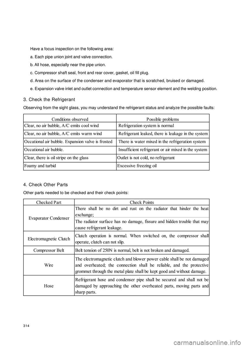
3. Check the Refrigerant
Observing from the sight glass, you may understand the refrigerant status and analyze the possible faults:
4. Check Other Parts
Other parts needed to be checked and their check points:Conditions obse rvedP ossible proble ms
Cle ar, no a ir bubble , A/C e mits c ool wind Re frige ra tion system is normal
Cle ar, no a ir bubble , A/C e mits warm wind Re frige ra nt le a ke d, the re is le aka ge in the syste m
Occ a tiona l a ir bubble . Expa nsion va lve is froste d There is wa te r mixe d in the re frigeration syste m
Occational air bubble. Insufficient refrigerant or air mixed in the system
Cle ar, the re is oil stripe on the gla ss Outle t is not c old, no refrige ra nt
Foamy and turbid Excessive freezing oilChecked PartCheck Points
The re sha ll be no dirt and rust on the radiator tha t hinde r the he at
exchange;
The ra dia tor surfa ce ha s no da mage , fissure a nd hidde n trouble tha t ma y
cause refrigerant leakage.
Elec tromagne tic Clutc hClutc h ope ration is norma l. Whe n switche d on, the c ompre ssor sha ll
operate, clutch can not slip.
Compre ssor Be lt Be lt te nsion of 250N is normal, belt is not broke n and dama ged.
WireThe electromagnetic clutch and blower power cable shall be not damaged
and overheated; the connection shall be reliable, and the protective
gromme t through the me tal plate sha ll be ke pt good a nd without da ma ge .
HoseRefrigerant hose and condenser pipe shall be secured and shall not be
dama ged by a pproac hing the othe r ove rhe ate d pa rts, moving pa rts a nd
sha rp parts. Eva pora tor Conde nse r
Page 322 of 392

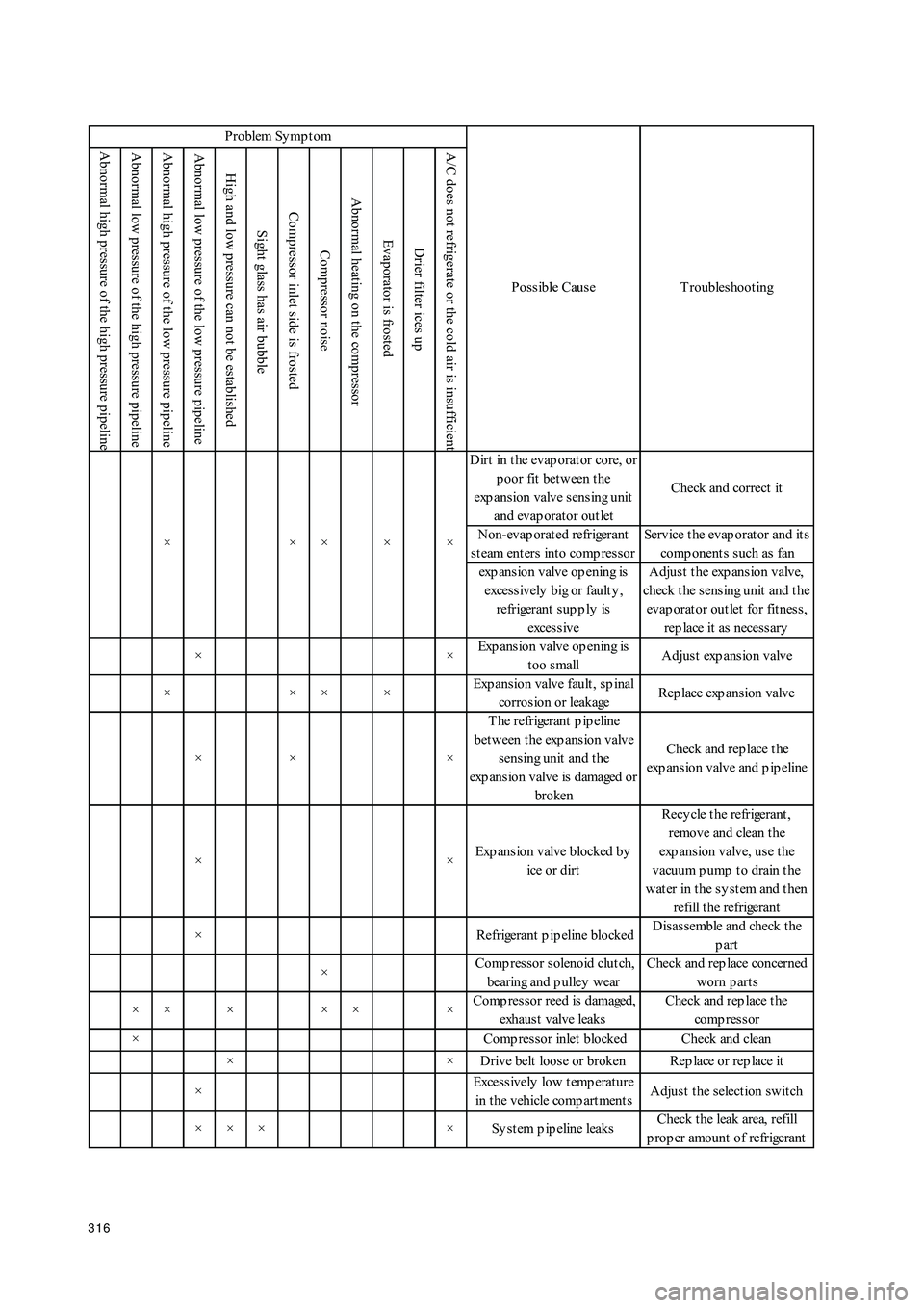
315II. A/C System Diagnosis and TroubleshootingTable 1 Abnormal high pressure of the high pressure pipelineAbnormal low pressure of the high pressure pipeline Abnormal high pressure of the low pressure pipelineAbnormal low pressure of the low pressure pipelineHigh and low pressure can not be establishedSight glass has air bubble Compressor inlet side is frosted Compressor noise Abnormal heating on the compressorEvaporator is frostedDrier filter ices up A/C does not refrigerate or the cold air is insufficient× × × × Excessive refill of refrigerantDrain p rop er amount of
refrigerant
× × × × T oo lit t le refill of refrigerantRep air t he gas leak area, refill
p rop er amount of refrigerant
× × × × Refrigerant is leaked allRep air t he gas leak area, refill
p rop er amount of refrigerant
×× ××× ×T here is non-clot t ed gas in
the sy stemLoos en receiver and
condenser inlet connect or,
discharge t he non-clot t ed gas
××Excessive freez ing oil in t he
sy stemCheck comp ressor freez ing
oil level, adjus t it
× Excessive high t emp erat ure
of condenser inletPerform t he check at t he
p lace w it h good vent ilat ion
T here is dus t in t he
condens er core, air channel
w it hin t he condens er is
blocked or suffocat edU s e comp res s ed air or w at er
t o flush and remove t he dirt
on t he condenser
Condenser fan faulty or
brokenCheck the wiring status and
t he fan mot or, correct or
rep lace it
×× Exces s ively low t emp erat ure
of condenser inletStop the op eration of the
refrigerat ion sy st em
× × × Drier blocked Clean
A ir channel in t he evap orat or
blocked or suffocat edRemove t he dirt on t he
evap orat or
Evap orat or fan fault , p oor
blower mot or w ire connect ionCheck the wiring status and
t he fan mot or, correct or
rep lace it
×× ×T here is dirt in evap orat or
coreU s e t he comp res s ed air t o
clean t he evap orat or core × ×
××××
× P roblem Sy mp t om
Possible Cause T roubleshoot ing
×
Page 323 of 392

316 Abnormal high pressure of the high pressure pipelineAbnormal low pressure of the high pressure pipeline Abnormal high pressure of the low pressure pipelineAbnormal low pressure of the low pressure pipelineHigh and low pressure can not be establishedSight glass has air bubble Compressor inlet side is frosted Compressor noise Abnormal heating on the compressorEvaporator is frostedDrier filter ices up A/C does not refrigerate or the cold air is insufficientD irt in t he evap orat or core, or
poor fit between the
exp ansion valve sensing unit
and evap orat or out letCheck and correct it
Non-evap orat ed refrigerant
steam enters into compressorService t he evap orat or and it s
comp onent s s uch as fan
exp ans ion valve op ening is
excessively big or faulty ,
refrigerant sup p ly is
exces s iveA djus t t he exp ans ion valve,
check t he s ens ing unit and t he
evap orat or out let for fit nes s ,
rep lace it as necess ary
××Exp ansion valve op ening is
too smallAdjust exp ansion valve
××××Exp ansion valve fault , sp inal
corrosion or leakageRep lace exp ans ion valve
×× ×T he refrigerant p ip eline
bet ween t he exp ansion valve
sensing unit and t he
exp ansion valve is damaged or
brokenCheck and rep lace t he
exp ansion valve and p ip eline
××Exp ansion valve blocked by
ice or dirtRecy cle t he refrigerant ,
remove and clean t he
exp ansion valve, use the
vacuum p ump t o drain t he
water in the system and then
refill t he refrigerant
× Refrigerant p ip eline blockedD is as s emble and check t he
part
× Comp ressor solenoid clutch,
bearing and p ulley w earCheck and rep lace concerned
worn p art s
×××××× Comp ressor reed is damaged,
exhaus t valve leaksCheck and rep lace t he
comp res s or
× Comp res s or inlet blocked Check and clean
× × D rive belt loos e or broken Rep lace or rep lace it
×Exces s ively low t emp erat ure
in t he vehicle comp art ment sAdjust the selection switch
× × × × Sy s t em p ip eline leaksCheck t he leak area, refill
p rop er amount of refrigerant × ×× Problem Symptom
Possible Cause T roubleshoot ing
××
Page 324 of 392

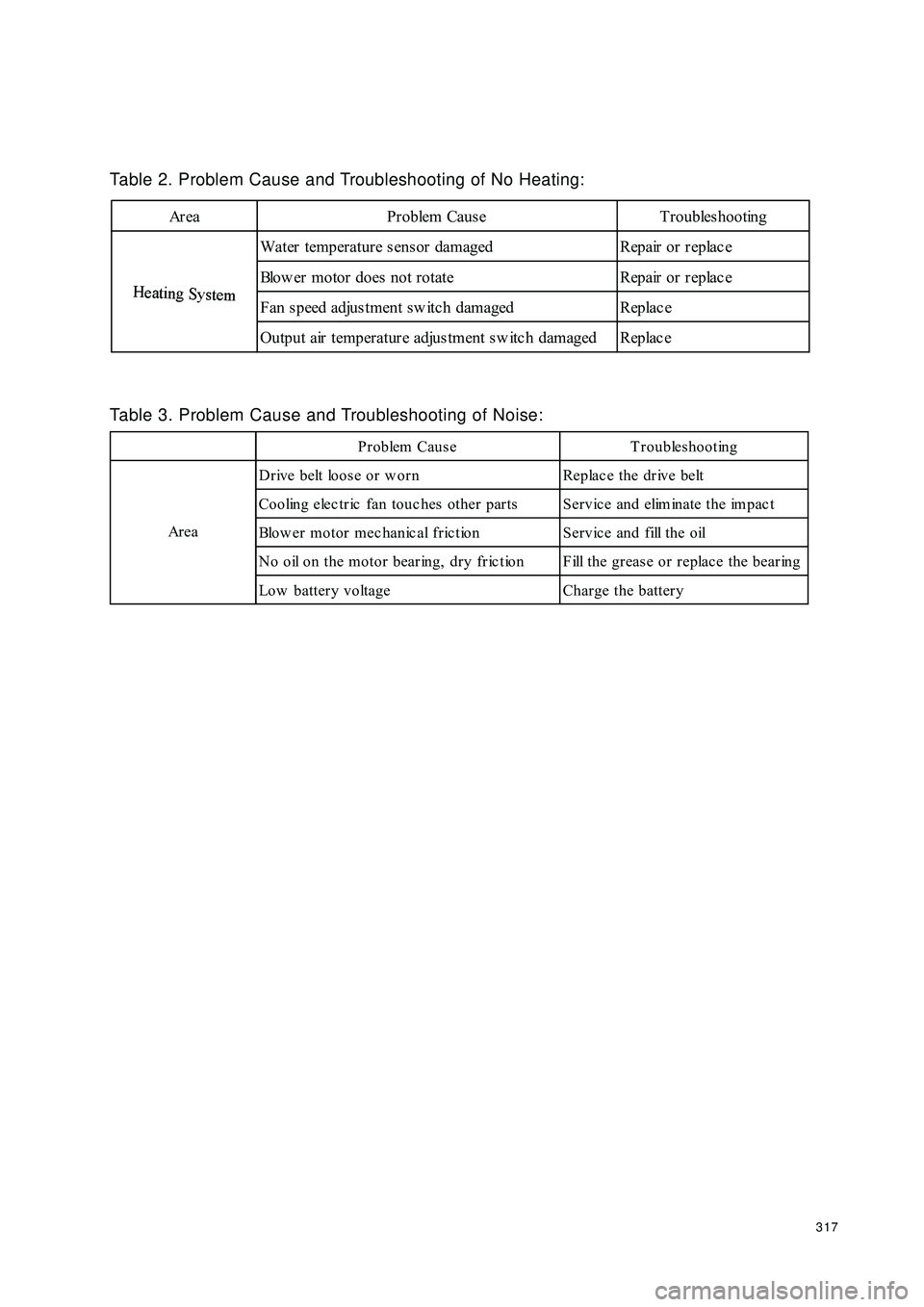
317Table 2. Problem Cause and Troubleshooting of No Heating:Area Problem Cause TroubleshootingH
eat
i
ng
Sy
st
emWater temperature sensor damaged Repair or replac e
Blow er motor does not rotate Repair or replac e
Fan s peed adjus tment sw itc h damaged Replac e
Output air temperature adjustment sw itc h damaged Replac eH
eat
i
ng
Sy
st
emTable 3. Problem Cause and Troubleshooting of Noise:Problem Cause Troubleshooting
Drive belt loose or w orn Replac e the drive belt
Cooling electric fan touc hes other parts Service and eliminate the impac t
Blow er motor mec hanic al fric tion Servic e and fill the oil
N o o il o n t h e m o t o r b e a r in g , d r y f r ic t io n F ill t h e g r e a s e o r r e p la c e t h e b e a r in g
Low battery voltage Charge the battery Ar e a
Page 325 of 392

318Chapter 2 Inside & outside Trim and AccessorySection 1 Configuration Index(I) Outside Trim And Front Accessory1 Door handle 6 Windshield
Front fender
(See the engine hood adjustment)
Front bumper
(See front bumper
r em o v a l/ in s t allat io n )
The engine hood
(See the engine hood
r em o v a l/ in s t a llat io n )
Elec tric outs ide rear view mirror
(See elec tric outs ide rear view
m ir r o r r em o v a l/ in s t allat io n ) 5 Co w l v e n t g r ille 1 0Front mudguard skirt
4 9 Fuel fill port cap 2 Ra d ia t o r g r ill a s s em b ly 7
38
Page 326 of 392

319(II) Outside Trim and Rear AccessoryRear trunk lid
(See rear trunk lid
r em o v a l/ in s t allat io n )
Rear trunk lid inside trim and
accessory
(See rear trunk lid
r em o v a l/ in s t allat io n )
2 Rear w indshield 9 Quarter Window glass
Rear lic ense box Rear door w eatherstrip
(See rear trunk lid
r em o v a l/ in s t allat io n )(See rear door removal/installation)
Rear bumper
(See rear bumper
r em o v a l/ in s t allat io n )
Rear door glass Front door w eatherstrip
(See rear door removal/installation) (See front door removal/installation)
6 Rear mudguard skirt 13 Rear trunk lock
7 Roof garnish 4 11 Rubbing strap
512 1 8 O u t e r d o o r s ill u n d er t h e t r im b o ar d
310
Page 327 of 392

320(III) Front inside trim613
7 Front door power window switc 14Elec tric outs ide rear view mirr or 5 Instrument panel end shield 12 Auxiliary console assembly 3 A/C panel assembl 10
411 1 A- pillar in s ide t r im 8
29
Low er en d s hield as s em b ly
Front row seat Front door insdie trim
Instrument panel assembly
Glove c ompartment as s embly
Steering column coverFront door sill inside trim
Front end of auxiliary c onsole
Page 328 of 392

321(IV) Rear inside trim1 Inner rear view mirror 10 Rear doorinside trim
2 I n t e r io r la m p 1 1 C- p illar u p p er in s id e t r im
Rear seat belt buckle
(See rear seat belt buckle
r e m o v al/ in s t allat io n ) r ear t r u n k
in s id e t r im
4 Sun visor 13 Rear trunk low er trim c over
5 B- p illar u p p er in s id e t r im 1 4 Lo w er r ea r t r im a s s em b ly
Rear s eat
( S ee r ea r s eat r em o v al/ in s t allat io n )
Fr ont s eat belt Rear s eat belt
( See f ront s eat belt
r em o v a l/ in s t a lla t io n )( See Rear s eat belt
r em o v a l/ in s t allat io n )
( See s eat belt ins pec tion) (See s eat belt ins pec tion)
8 B- p illar lo w er in s id e t r im 1 7 Rea r d o o r s ill in s id e t r im
9 Safe handle 18 Carpet & sound insulator 716 3 A- p illar in s id e t r im 1 2
6 Roof ins ide trim 15
Page 329 of 392

322Section 2 Inside & Outside Trim and Accessories Removal and
Installation(I) Front BumperThe structure is as shown in the figure below:
1. Front Bumper 2.Front Bumper Fixed Screw3.Secondary Bumper Assembly Upper Buckle and Plug
4.Mounting Plate Cross Head Counter Sunk Self-tapping Screw5.Mounting Plate Cross Head
Counter Sunk Self-tapping Screw 6.Front Bumper Mounting Bracket to Body Bolt 7.Front Bumper
Mounting Bracket Sub-assembly 8. Secondary Bumper Assembly9.Front Bumper Mounting
Bracket to Secondary Bumper Assembly Bolt 10.Front Bumper Cushion 11.Secondary Bumper
Assembly Lower Buckle and Plug 12.License Mounting Plate Assembly13.Secondary Bumper As-
sembly Lower Connecting Bolt 14.Front Bumper Mounting Plate Seat15.Mounting Plate Seat Bolt
16.Front Bumper Mounting Plate
Page 330 of 392

3231. Front Bumper Removal and Installation
(1) Disconnect the negative (--) terminal cable from the battery. Disconnect fog lamp wire;
(2) Remove the mudguard skirt to front bumper clip;
(3) Remove the attaching bolt of the the front fender and panel and the front bumper sub-assembly;
(4) Remove the front bumper set screw and the clip. Remove the front bumper mounting plate and the
positioning screw of the seat;
(5) Remove the bolt which connecting front bumper mounting bracket with the vehicle body;
(6) Pull the front bumper assembly and the secondary bumper assembly together out of the vehicle body.
Separate the front bumper mounting bracket from the rail, front bumper mounting plate from the front
bumper mounting plate seat;
(7) Remove the front bumper mounting plate seat from the vehicle body;
(8) Remove the secondary bumper assembly and the front bumper mounting bracket sub-assembly;
(9) Remove front bumper mounting plate;
(11)Remove front bumper cushion. Remove the front license plate. Remove the mounting plate assembly;
(12)Remove fog lamp;
(13)The installation is in the reverse order of the removal.
2.Notice For Removal Of The Front Bumper
(1) Pull the front bumper to separate it from the bumper rail.
(2) Uniformly pull it by force to prevent the front bumper mounting plate and seat from damage.
Warning
�