GEELY CK 2008 Workshop Manual
Manufacturer: GEELY, Model Year: 2008, Model line: CK, Model: GEELY CK 2008Pages: 392, PDF Size: 38.86 MB
Page 361 of 392

354Rear door
Rear door Component
1.Rear Door 2.Rear Door Hinges 3.Rear Door Lock And Door Lock Actuator
4.Rear Door Inner Trim Board 5.Power Window Motor 6.Power Window Actuator
7.Door Inside Handle 8.Door Outside Handle 9.Rear Window Glass 10.Quarter Window
11.Window Glass Regulator Run 12.Glass Run13.Quarter Window Weatherstrip
14. Rear Door Weatherstrip A 15.Rear Door Lower Weatherstrip 16.Rear Door Weatherstrip B
17.Rear Door Lock Striker
1.Rear Door Removal/Installation
(1) Disconnect the negative (--) terminal cable from the battery.
(2) Remove the connector.
(3) Remove rear door hinges.
(4) Remove the rear door
(5) The installation is in the reverse order of the removal.
(6) Adjust the rear door. (See Rear door Adjustment)1
2 3
4
5 6
7 8
9 10
12 13
15 11 14 17
16
Page 362 of 392

355Rear Doorinside Trim
Rear Doorinside Trim Component:
1.Rear Doorinside Trim Board Assembly2.Rear Door Lock Inner Handle Assembly
3.Controller
Trim Board 4.Door Handle5.Set Screw
1.Rear doorinside trim board removal/installation
(1) Remove the set screw. (See Figure 5)
(2) Remove the rear door inside trim board assembly.
(3) Disassemble the inside trim board assembly as required
(4) The installation is in the reverse order of the removal.1 2 3 4 5
Page 363 of 392

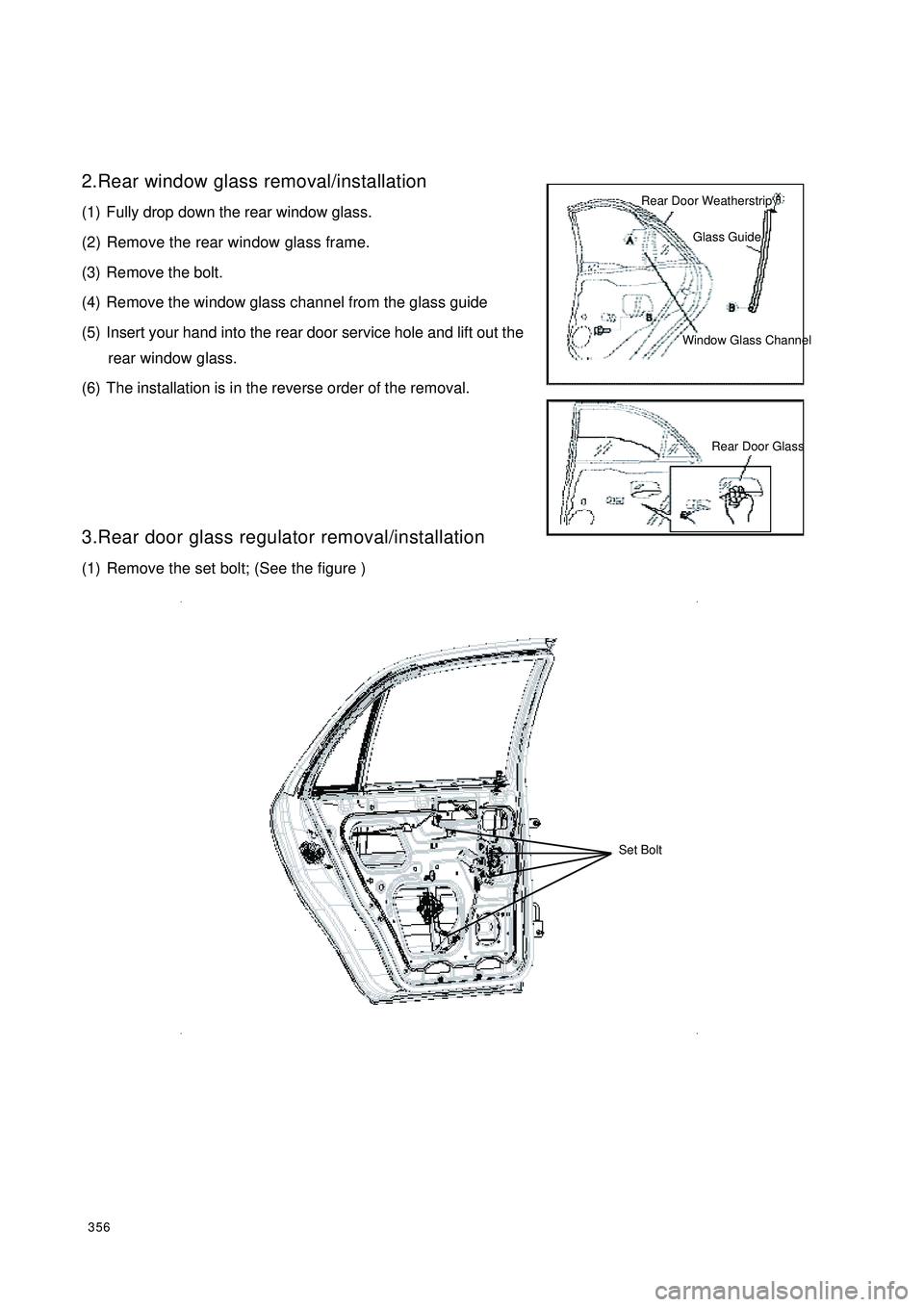
3562.Rear window glass removal/installation
(1) Fully drop down the rear window glass.
(2) Remove the rear window glass frame.
(3) Remove the bolt.
(4) Remove the window glass channel from the glass guide
(5) Insert your hand into the rear door service hole and lift out the
rear window glass.
(6) The installation is in the reverse order of the removal.
3.Rear door glass regulator removal/installation
(1) Remove the set bolt; (See the figure )Rear Door WeatherstripGlass GuideWindow Glass ChannelRear Door Glass Set Bolt
Page 364 of 392

357(2) Take out the rear door glass regulator from the square hole under the door;
4.Rear door lock and door lock actuator removal/in
stallation
(1) Remove the rear door component.
(2) Remove the screw and then remove rear door lock and the
door lock actuator.
(3) The installation is in the reverse order of the removal. Power Window Glass
Regulator Actuator
Rear Door ComponentPower Window Glass
Regulator MotorRear Door Lock Latch
and Lock Motor Screw
Page 365 of 392

358Door Adjustment1. Measure clearance between the front door or the rear door and the vehicle body.
2. Loose the front door or the rear door hinges assembly bolt or door lock striker assembly screw
and reinstall it to the door if the measured result is not as specified in the technical standard.
Clearance
a: 5mm
b: 5mm
c: 4.3mm
d: 4.3mm
e: 3.8mm
f: 4.6mm
3. Tighten the bolt or the screw.
Page 366 of 392

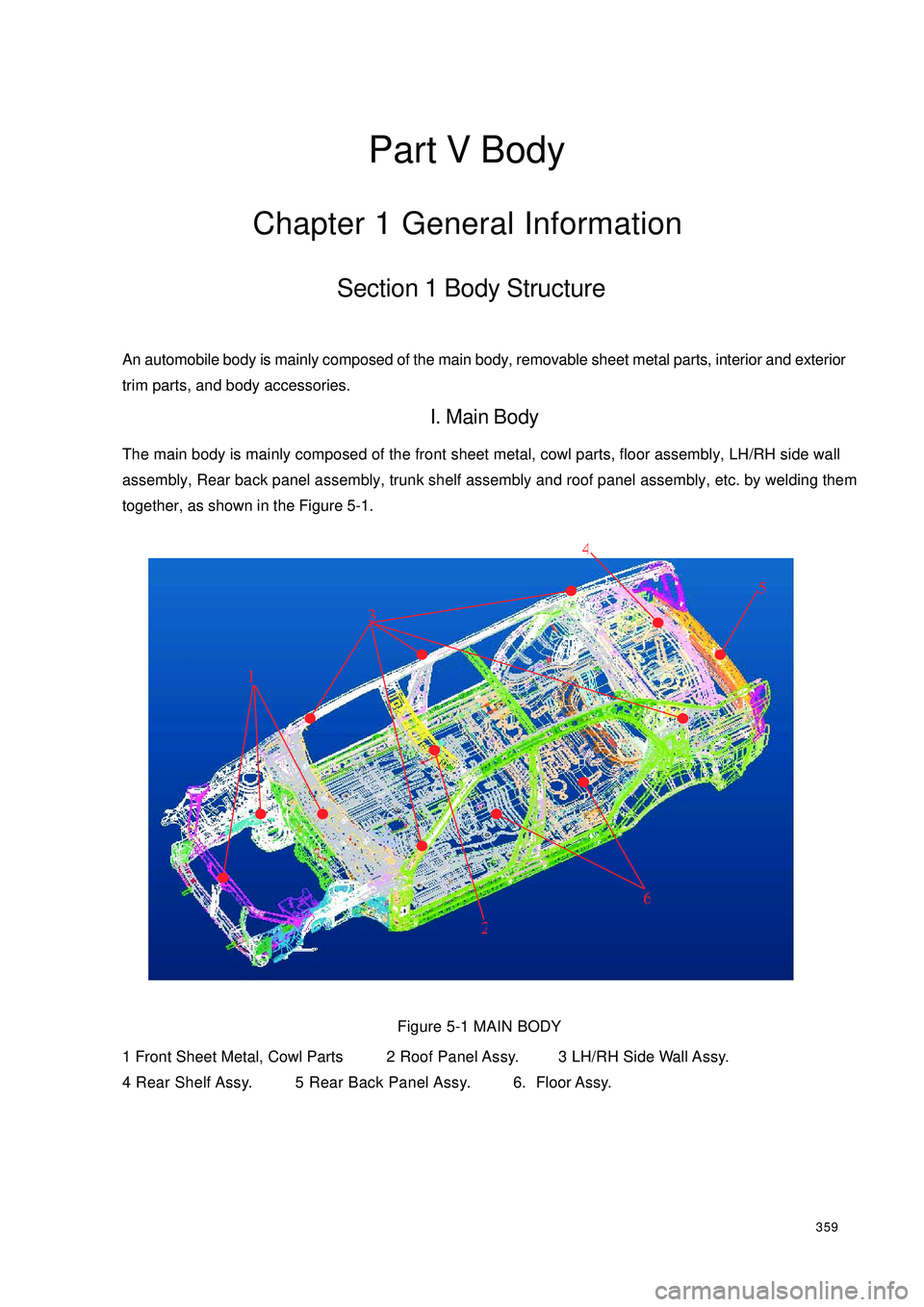
359Part V BodyChapter 1 General InformationSection 1 Body StructureAn automobile body is mainly composed of the main body, removable sheet metal parts, interior and exterior
trim parts, and body accessories.I. Main BodyThe main body is mainly composed of the front sheet metal, cowl parts, floor assembly, LH/RH side wall
assembly, Rear back panel assembly, trunk shelf assembly and roof panel assembly, etc. by welding them
together, as shown in the Figure 5-1.
Figure 5-1 MAIN BODY
1 Front Sheet Metal, Cowl Parts2 Roof Panel Assy. 3 LH/RH Side Wall Assy.
4 Rear Shelf Assy. 5 Rear Back Panel Assy. 6. Floor Assy.
124563
Page 367 of 392

360(I) Front Sheet Metal, Cowl PartsThe main function of the front sheet metal and the cowl parts is forming an engine compartment to supply the
engine and accessories with a protective cover and to absorb the most energy when vehicle encounters
frontal impaction, protecting mud from being splashed by the front wheels, and meeting the requirements of
body design in appearance. It is mainly composed of front cross member assembly, LH/RH front mud guard
and front side member assembly, engine hood front support plate assembly, hood lock bracket assembly,
cowl assembly, cowl upper assembly.
1. Front Cross Member Assembly
The front cross member assembly is mainly composed of the front cross member welding sub-assembly,
front cross member bottom plate assembly, LH/RH side member end plate by welding them together, and its
dismantle diagram as shown in the Figure 5-2.
2. Lh/Rh Front Mudguard And Front Side Member Assembly
LH/RH front mud guard and front side member assembly is mainly composed of LH/RH front mudguards
and LH/RH side members by welding them together.
It is mainly used to mount some mounting brackets such as the engine LH/RH side suspension bracket, LH/
RH front suspension shock absorber bracket, etc. and to mount the LH/RH front fenders.
3. Engine Hood Front Support Plate Assembly
Engine hood front support plate is mainly composed of LH/RH headlamp mounting bracket assembly, hood
front support plate sub-assembly, and LH/RH front support plate reinforcement, by welding them together.
Engine hood front support plate assembly is used to mount radiator, engine hood lock, radiator grille, front
bumper, and headlamp.
4. Engine Hood Lock Bracket Assembly
Engine hood lock bracket assembly is used to mount the engine hood lock, also to strengthen the intensity and
rigidity of the front body by connecting the engine hood front support plate and front cross member.
5. Cowl Assembly
Cowl assembly is mainly composed of cowl inner and outer plate assembly and cowl lower cross member, by
welding them together.
Cowl assembly and front floor, LH/RH front mud guard (LH/RH front pillar), cowl upper baffle is welded
together, which forms a framework with great torsional strength. It generates great resistance to lateral
impact and rolled deformation.
Cowl inner and outer plate assembly is sandwich structure. 3mm of asphalt plate lies in the interlayer, which
is to cut off the noise and heat generated from the engine.
Page 368 of 392

3616. Cowl Upper Assembly
Cowl upper assembly is mainly composed of cowl upper outer plate, cowl upper LH/RH end plate assembly,
instrument panel mounting plate, steering column mounting bracket upper/lower plate, cowl lower inner plate,
ventilator cover, etc., by welding them together.
Figure 5-2 Dismantle diagram of front sheet metal and cowl parts
1 Front Cross Member 2 Hood Lock Bracket Assy. 3 LH/RH Side Member End Plate
4 Engine Hood Front Support Plate Assy. 5 LH/RH Front Cross Member 6. LH/RH Front Mud Guard
7 Front Cross Member Assy. 8 Cowl Inner And Outer Plate Assy. 9 LH/RH Front Mud Guard
Reinforcement 10 Cowl Upper Baffle12 375683910 64Front
Page 369 of 392

362(II) Floor AssemblyFloor assembly is the base of the main body and an important structure component to link with assemblies
and for load transfer and bearing. The vehicle running performance depends on its intensity and rigidity.
Figure 5-3 is the dismantle diagram of the floor parts.
Floor assembly is composed of front floor assembly and rear floor assembly. A protrusile tunnel runs longitu-
dinally in the center of the front floor. The tunnel and the lower floor rail can strengthen its rigidity in
longitudinal direction. The lower space of the tunnel is used to mount components such as transmission shift
pull rod, park brake drawing cable, exhaust pipes with 3-way catalytic converter. Carpet and sound insulator
mat are mounted in the inner side of the compartment. The first and the second cross member, LH/RH side
member and side rails which are on the front floor form a frame structure. It can provide great load-bearing
capacity to assure strict running requirements for body.
Figure 5-3 Decomposition Diagram of Floor Parts
1 LH/RH Front Floor Side Rail 2 Front Floor 3 Front Floor Cross Member 4 LH/RH Floor Side
Member 5 Rear Floor 1st Cross Member 6 LH/RH Rear Floor Side Rail 7 Rear Floor 2nd Cross
Member Assy. 8 Rear Floor2143456 678Front
Page 370 of 392

363 (III) Side Wall AssemblyLH/RH side wall assembly is frame structure. It is mainly composed of parts such as LH/RH front pillar sub-
assembly, LH/RH central pillar reinforcement, LH/RH upper side rail, LH/RH floor side rail outer panel, LH/
RH side wall inner/outer panel...etc., by welding them together. Figure 5-4 is the dismantle diagram.
Figure 5-4 Decomposition Diagram of Quarter Parts
1. LH/RH Front Pillar Inner Plate 2 LH/RH Upper Side Member Front Inner Plate 3 LH/RH Front
Pillar Outer Plate Reinforcement 4 LH/RH Upper Side Member Inner Plate Assy.
5.LH/RH Doorframe Lower Side Member Outer Plate Reinforcement 6 LH/RH Central Pil-
lar Outer Plate Reinforcement 7 LH/RH Rear Wheel House Inner Plate Sub-assy 8 LH/RH Rear
Wheel House Outer Plate Sub-assy 9 LH/RH Side Wall Outer Plate 157926485874293163 Front Left
Right