HONDA INTEGRA 1998 4.G Workshop Manual
Manufacturer: HONDA, Model Year: 1998, Model line: INTEGRA, Model: HONDA INTEGRA 1998 4.GPages: 1681, PDF Size: 54.22 MB
Page 1181 of 1681
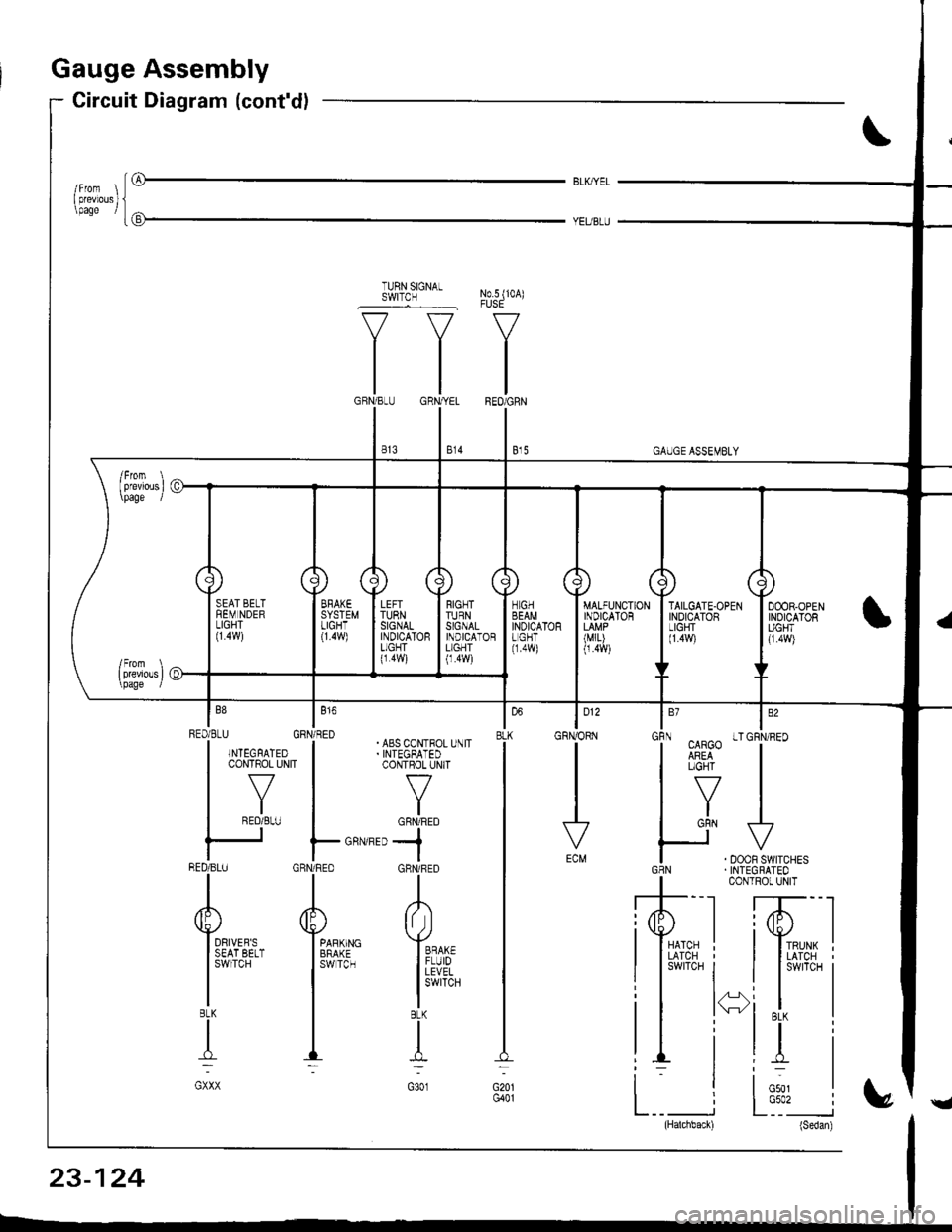
auge Assembly
Circuit Diagram (cont'dl
iG
BLK,IYEL
No.5 (10A)
V
IREO/GRN
I e,s
TURN SIGNALSWITCN
v--=v
tltl
tlGBN/BLIJ GRN,YEL
lltl
I e's I s,o
"i.uv"'T""
H^,J.**.GBN . INTEGRATEO
I coNrRor uNrT
,'T--l ffi--l
lI*ni lI*i
il i*i t i
i. li;, I
L__ i L:'�_" i(Hatchback) (Sedan)
| 012
GRNORN
vECM
louBLK
G20lG401
RIGNTTURNSIGNALINDICATORL]GHT(1.4w)
TAILGATE.OPENINDICATORLIGHT(1.4!9
RED/BLU GBN/RED| | . ABS CoN-FOL U\lTI .NTEGFATED I .INTEGBATED
|
*v^"
|
-'v*
| .roL-" I or*frro
ts Fo.''-,,-jBED/BLU GRN/RED GHNi RED
rrl
AAA
Yu'**- Y*,,r" Y**
l3$i;.?.'' 13ffi3- ll#,
| | l!i,Iib'.
TIT:-_:
GXXX G3O1
23-124
Page 1182 of 1681
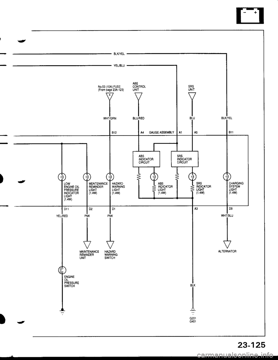
J
BLKYEL
YEUBLU
A8SN0.53 (104) FUSE CONTROLlFrofi page 23A'123) UNIT
VV
II
tltlWHT/GFN BLU/REO
lonWHT€IU
I
I
I
\?
ALTERNATOR
lo'PNK
J
HAZAROWARNINGswtTcH
MENTENANCEREMINDERLIGHT0.4v,/i
lo'PNK
II
I
J
MAINTENANCEREMINDERUNIT
| 011
YEUREO
I
T
P"-:
)-
BLK
I:
G201G401
LOWENGINE OILPFESSUREINDICATORLIGHT0.4w)
23-125
)J
Page 1183 of 1681
1.
2.
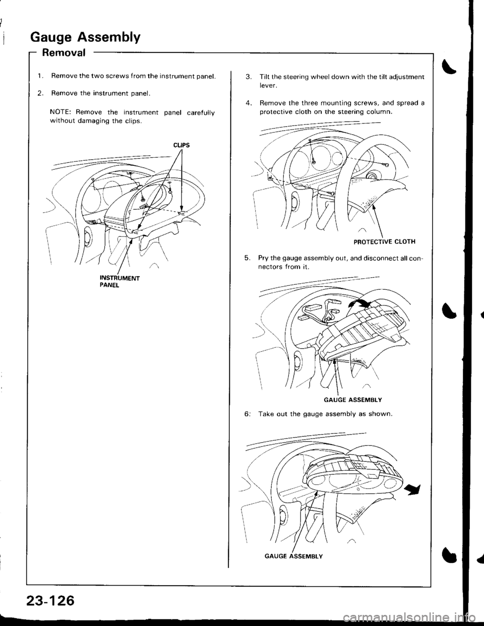
Gauge Assembly
Removal
Remove the two screws from the instrument panel.
Remove the instrument panel.
NOTE: Remove the instrument panel carefully
without damaging the clips.
23-126
3.
5.
Tilt the steering wheel down with the tilt adjustment
lever.
Remove the three mounting screws, and spread a
protective cloth on the steering column.
PROTECTIVE CLOTH
Pry the gauge assembly out, and disconnect all con
nectors from it.
6:
GAUGE ASSEMBLY
Take out the gauge assembly as shown.
GAUGE ASSEMBLY
Page 1184 of 1681
{
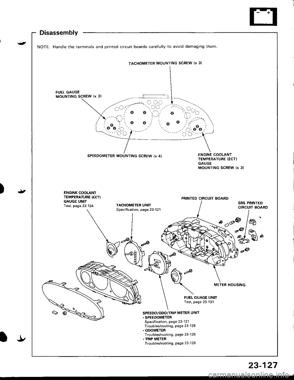
Disassembly
NOTE: Handle the terminals and Drinted circuit boards carelully to avoid damaging them.
FUEL GAUGEMOUNTING SCBEW {x 3l
e
o
SPEEDOMETER MOUNTING SCREW (x 4)ENGINE COOLANTTEMPERATURE {ECT)GAUGEMOUNTING SCREW {x 3}
t)ENGINE COOLANTTEMPERATURE IECTIGAUGE UNITTest, page 23-134TACHOMETEF UNITSpecification, page 23-121
SRS PRINTEDCIRCUIT BOARD
d'dP
METER HOUSTNG
FUEL GUAGE UNITTest, page 23 131
'
/*'
r@/ ror
6rH"
SPEEDO/ODO/TRIP METER UNTT' SPEEDOMETERSpecification, page 23-121Troubleshooting, Page 23_128. ODOMETERTroubleshooting, page 23-128. TRIP METERTroubleshooting, Page 23 128
TACHOMETER MOUNTING SCREW {x 3)
PRINTED CIRCUIT BOARD
It
23-127
Page 1185 of 1681
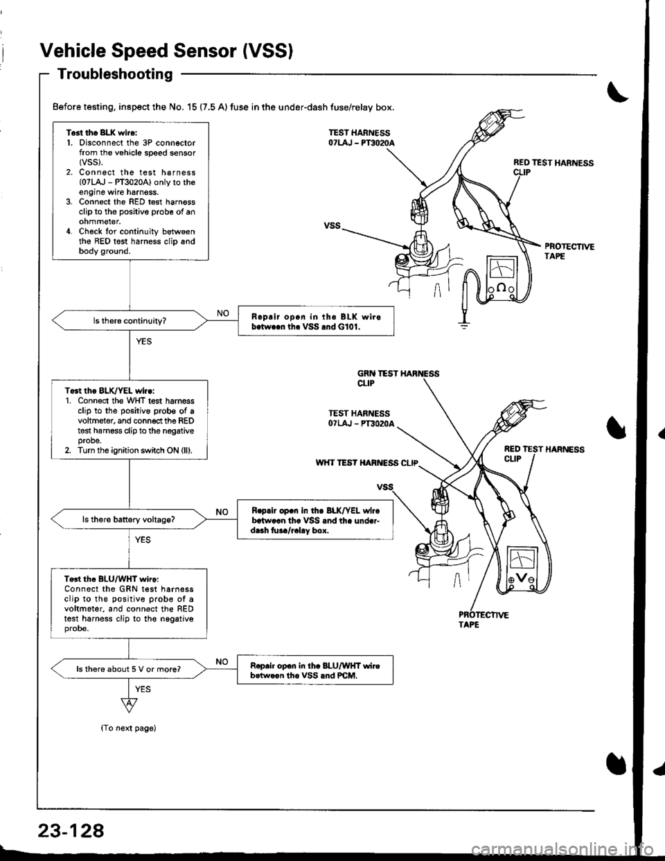
Vehicle Speed Sensor (VSSI
Troubleshooting
{To next page)
REO TEST HARNESS
PBOTECTIVETAPE
Test tho 8LK wiro:1. Disconnect the 3P connectorfrom the vohicle speed sensor(vss).
2. Connect the test harness(07LA,J - PT3020A) only to theengine wire harnoss.3, Connect the RED test harnessclip to the positive probe of anohmmel€r.4. Check for continuity betwoenthe RED test harness clip andbody ground.
Roplir op.n in th. BLK wirob.tw..n tha VSS .nd G101.
To3t thc BLK/YEL wiro:1. Conn6ct th€ WHT test harnessclip to the positive prob€ of avoltmeter, and connect the REDt€st harness clip to the nogativeprobe.2. Turn the ignition switch ON (lll.
R.p.lr op.n In tho BLK/YEL wirebrtw..n th. VSS and th. under-dr.h tu../r.l!y box.
Tort th. BLU/WHT wiro:Connect the GRN test harnessclip to the positive prob€ ot avoltmeter, and connect the REDtest harness clip to the nggatjveprobe.
Roprh op.n in th. 8LU/WHT wireb.tw.on tho VSS lnd PCM.ls there about 5 V or more?
Before testing, inspect the No. 15 (7,5 A) fuse in the under-dash fuse/relay box.
GRN TESTCLIP
TEST HARNESSOTLAJ - PT3O2OA
w'{T TES? HARIVESS CLIP
TAPE
23-128
Page 1186 of 1681
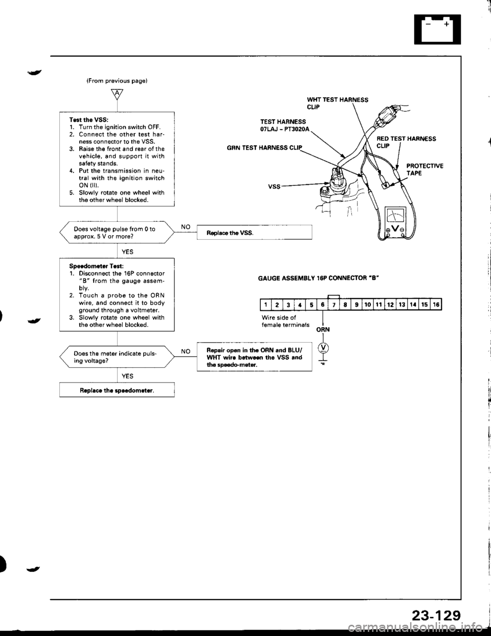
Test tho vss:1. Turn the ignition switch OFF.2. Connect the other test harness connector to the VSS.3. Raise th€ front and roar of thevehicle, and support it withsafety stands.4. Put the transmission in neu-tral with the ignition switchoN flr).5. Slowly rotate one wheel withthe other wheel blocked.
Does voltage pulse from 0 toapprox.5 V or more?
Spocdomatcr Te3t:1. Disconnoct the 16P conngctor"B" from the gauge assem-
2. Touch 8 probe to the ORNwire, and connect it to bodyground through a voltmetor.3. Slowly rotate one wheel withthe other wheel blocked.
Repair open in the ORN and BLU/WHT wire botw.en tho VSS .ndthe soa€do-mster.
Does the meter indicate puls-ing voltage?
{
{
WHT TESTCLIP
TEST HABNESSOTLAJ - PT3O2OA
FED TEST HARNESSCLIPGRN TEST HARNESS CLIP
GAUGE ASSEMBLY 16P CONNECTOR '8"
PROTECTIVETAPE
){
Page 1187 of 1681
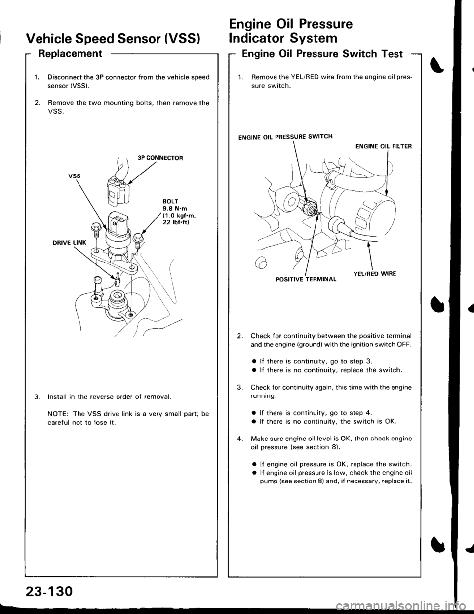
1. Disconnect the 3P connector from the vehicle speed
sensor (VSSl.
2. Remove the two mounting bolts, then remove the
VSS.
3P CONNECTOR
BOLT9.8 N.m(1.O kgf.m,22 tbt,ltl
DRIVE LINK
3.Install in the reverse order of removal.
NOTE: The VSS drive link is a very small part;
careful not to lose it.
DC
Vehicle Speed Sensor (VSS)
Engine Oil Pressure
lndicator System
ReplacementEngine Oil Pressure Switch Test
23-130
E-_
1 . Remove the YEL/RED wire trom the engine oil pres-
sure swlrcn.
ENGINE OIL PBESSURE SWITCH
Check for continuity between the positive terminal
and the engine (ground) with the ignition switch OFF.
a lf there is continuity, go to step 3.
a lf there is no continuity, replace the switch.
Check lor continuity again, this time with the engine
running.
a lf there is continuity, go to step 4.
a lf there is no continuity, the switch is OK.
Make sure engine oil level is OK, then check engine
oil pressure (see section 8).
a lf engine oil pressure is OK, replace the switch.
a lf engine oil pressure is low, check the engine oil
pump (see section 8) and, iI necessary, replace it.
2.
3.
POSITIVE TERMINAL
Page 1188 of 1681
)
{
t.t
t.!
23-131
Fuel Gauge
Gauge Test
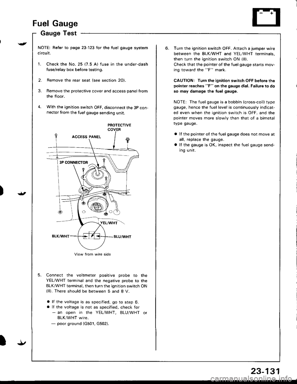
NOTE: Refer to page 23-123 for the fuel gauge system
circuit.
1. Check the No. 25 (7.5 A) fuse in the under-dash
fuse/relay box before testing.
2. Remove the rear seat (see section 20).
Remove the protective cover and access panel from
the tloor.
With the ignition switch OFF, disconnect the 3p con-nector from the fuel gauge sending unit.
3.
4.
5.
PROTECTIVECOVER
Connect the voltmeter positive probe to the
YEL/WHT terminal and the negative probe to the
BLK/WHT terminal, then turn the ignition switch ON(ll). The.e should be between 5 and 8 V.
a lf the voltage is as specified, go to step 6.a lI the voltage is not as specified, check for- an open in the YEL/WHT, BLU/WHT or
BLK/WHT wire.- poor ground (G501, G502).
3P CONNECTOR
View from wire side
6.Turn the ignition switch OFF. Attach a jumper wire
between the BLKMHT and YEL/WHT terminals,
then turn the ignition switch ON {1.,.
Check that the pointer of the fuel gauge starls mov-
ing toward the "F" mark.
CAUTION: Turn the ignition switch OFF before the
pointer reaches "F" on the gauge dial, Failure to do
so may damage the tuel gauge.
NOTE: The fuel gauge is a bobbin (cross-coil) type
gauge, hence the fuel level is continuously indicat-
ed even when the ignition switch is OFF, and thepointer moves more slowlv than that ol a bimetal
rype gauge.
a lf the pointer ol the fuel gauge does not move at
all, replace the gauge.
a It the gauge is OK, inspect the fuel gauge send-
ing unit.
Page 1189 of 1681
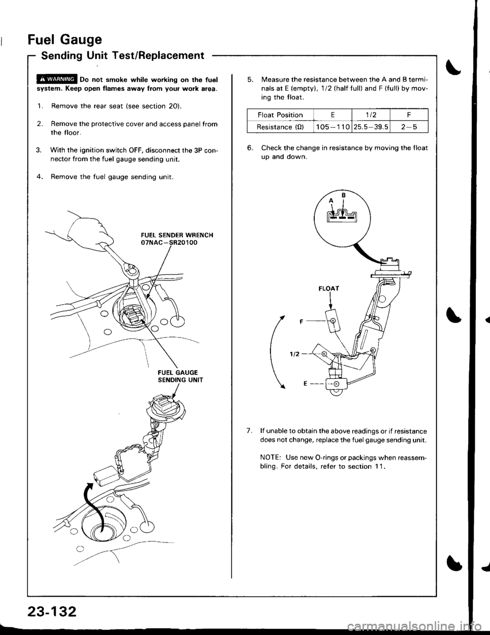
Fuel Gauge
Sending Unit Test/Replacement
@oo not smoke while working on tha fu6l
system. Keep open llames away trom youl work alea.
1. Remove the rear seat {see section 2O}.
2. Remove the protective cover and access panel trom
the floor.
3. With the ignition switch OFF, disconnect the 3P con-
nector from the fuel gauge sending unit.
4. Remove the fuel gauge sending unit.
o
23-132
Float PositionE1t2F
Resistance (Ol105 - 1 1025.5 39.525
5. lreasure the resistance between the A and B termi-
nals at E (empty), l/2(half full) andF{full} bymov-
ing the tloat.
6. Check the change in resistance by moving the float
uo and down.
(
1.lf unable to obtain the above readings or if resistance
does not change, replace the fuel gauge sending unit.
NOTE: Use new O-rings or packings when reassem-
bling. For details, refer to section 1 1.
Page 1190 of 1681
I
Seat Belt Reminder
SystemLow Fuel lndicator
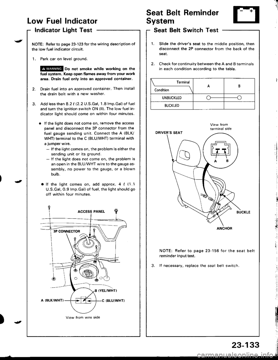
Indicator Light Test
NOTE: Refer to page 23-123 for the wiring description of
the low fuel indicator circuit.
1. Park car on level ground.
@ oo not smoke whilc wolking on the
fuel system. Keep open tlames away from your work
area. Drain fuel only into an approved container.
2. Drain fuel into an approved container. Then install
the drain bolt with a new washer.
3. Add lessthan 8.2 t l2.2U.S.Gal, 1.8 lmp.Gal)of fuel
and turn the ignition switch ON {ll). The low fuel in-
dicator light should come on within lour minutes.
. lf the light does not come on. remove the access
panel and disconnect the 3P connector from the
fuel gauge sending unit. Connect the A (BLV
WHT) terminal to the C (BLU,/WHT) terminal with
a jumper wire.
- lf the Iight comes on, the problem is either the
sending unit or its ground.- lf the light does not come on, the problem is
an open in the BLU/WHT wire to the gauge as-
sembly, no power to the gauge, or a blown
bulb.
a lf the light comes on, add approx.4 ! (1.1
U.S.Gal. O.9 lmp.Gal) of fuel, the light should go
off within four minutes.
I
i
)
SeatSwitchTestBelt
1.Slide the driver's seat to the middle position. then
disconnect the 2P connector from the back of the
seat.
Check tor continuity between the A and B terminals
in each condition according to the table.
NOTE: Refer to page 23-156 for the seat belt
reminder input test,
3. lf necessary, replace the seat belt switch.
Terminal
c""dil----lB
UNBUCKLEDoo
BUCKLED
ANCHOR3P CONNECTOR
23-133