HONDA INTEGRA 1998 4.G Workshop Manual
Manufacturer: HONDA, Model Year: 1998, Model line: INTEGRA, Model: HONDA INTEGRA 1998 4.GPages: 1681, PDF Size: 54.22 MB
Page 541 of 1681
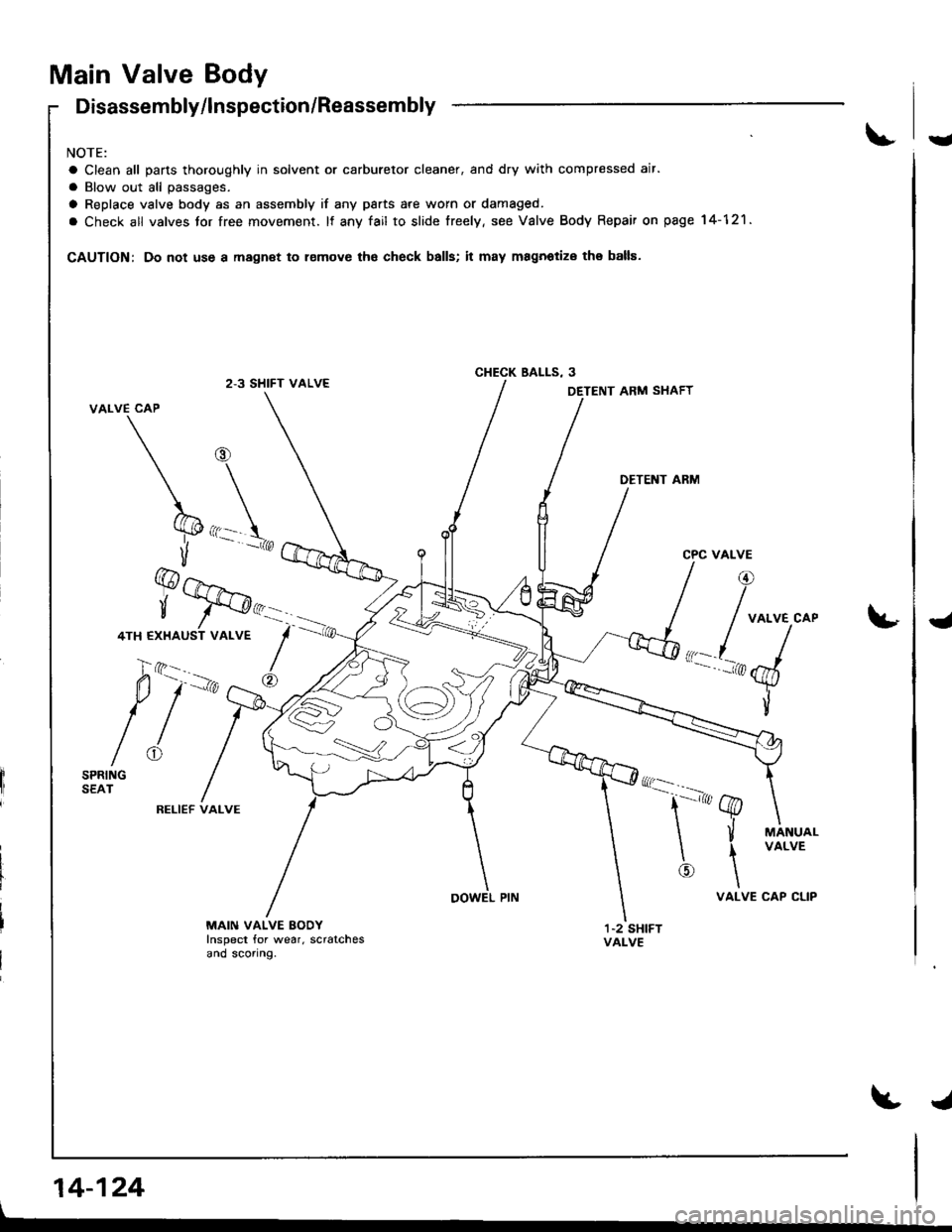
Main Valve Body
Disassembly/lnspection/Reassembly
NOTE:
a Clean all pans thoroughly in solvent or carburetor cleaner, and dry with compressed air.
a Blow out all passages.
a Replace valve body as an assembly if any psrts 8re worn or damaged.
a Check all valves tor free movement. It anv fail to slide freely, see Valve Body Repair on page 14-121.
CAUTION: Do not use a magnet to lemove tho check balls; it may magnoliz€ the balls.
2-3 SHIFT VALVECHECK BALLS. 3
14-124
ARM SHAFT
DETENT ARM
RELIEF VALVE
MAIN VALVE BODYInspect for wear. scratchesand sconng.
Y
I
Page 542 of 1681
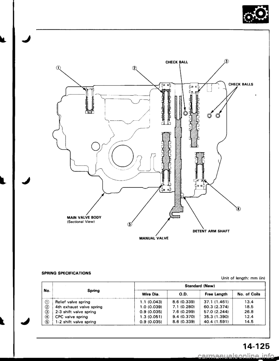
DETENT ARM SHAFT
MANUAL VALVE
SPRING SPECIFICATIONS
\
Unit ot length: mm (in)
No.Spdng
Stsndard {N€w}
Wi.s Dia.o.D.Fro€ LsngthNo. ot Coils
o
@
@
\9
Relief valve spring
4th exhaust valve spring
2-3 shift valve spring
CPC valve spring
1-2 shift valve spring
1 .1 (O.O43)
1 .0 (o.o39)
o.9 (o.o35)
1 .3 (0.O51)
o.9 (o.035)
8.6 (O.339)
7.1 (O.280)
7.6 (O.299)
9.4 {0.370)
8.6 (O.339)
37.1 (1 .461)
60.3 (2.374)
57 .O t2.244].
35.3 (1 .390)
40.4 (1 .591)
1 8.5
zo.6
14.5
14-125
Page 543 of 1681
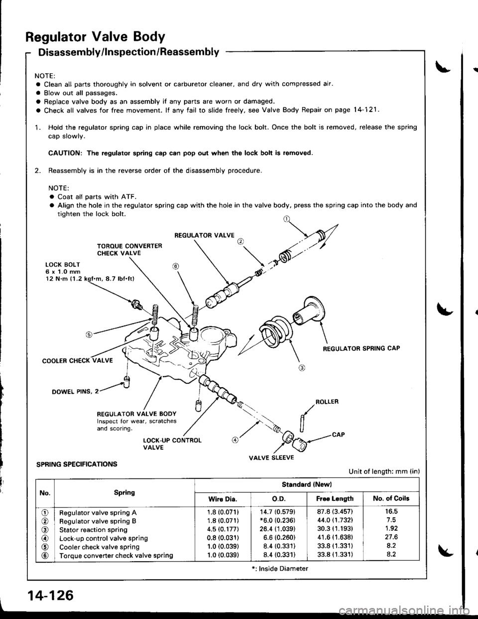
Regulator Valve Body
Disassembly/lnspection /Reassembly
NOTE:
a Clean all parts thoroughly in solvent or carburetor cleaner. and dry with compressed air.
a Blow out all passages.
a Replace valve body as an assembly if any parts are worn or damaged.
a Check all valves for free movement. lf any fail to slide freely, see Valve Body Repair on page 14-121.
1. Hold the regulator spring cap in place while removing the lock bolt. Once the bolt is removed. release the spring
cap slowly.
CAUTION: The regulator sp ng c8p can pop out when the lock bolt is r€moved.
2. Reassembly is in the reverse order of the disassembly procedure.
NOTE:
. Coat all pans with ATF.
a Align the hole in the regulator spring cap with the hole in the valve body, press the spring cap into the body and
tighten the lock bolt.
LOCK BOLT6 x 1.O mm12 N.m 11.2
COOLER CHECK
DOWEL PINS, 2
REGULATOR SPRING CAP
ROLLER
REGULATOR VALVE BODYInspect for wear, scratchesand sconng.
oi.
.. /
,/ i>, ll
,/ "W_-
VALVE SLEEVE
@LOCK-UP CONTROLVALVE
SPRING SPECIFICATIONSUnit of length; mm (in)
No.Spring
Standard {Newl
Wiro Dia.o.D.Froo LongthNo. of Coils
o
@
@
@rA
@
Regulator valve spring A
Regulator valve spring B
Stator reaction spring
Lock-up control valve sprlng
Cooler check valve spring
Torque converter check valve spring
1.8 (0.071)
1.8 (0.071)
4.5lO.177l
0.8 (0.031)
1.0 (0.039)
1.0 (0.039)
14.7 {0.579}*6.0 (0.236)
26.4 (1.039)
6.6 (0.260)
8.4 (0.331)
8.4 (0.331)
87.8 (3.457)
44.0 \1.1321
30.3 (1.1931
41.6 (1.638)
33.8 (1.331)
33.8 (1.331)
to.c
1.92
27.6
8.2
4.2
*: lnside Diameter
, 14-126
!
Page 544 of 1681
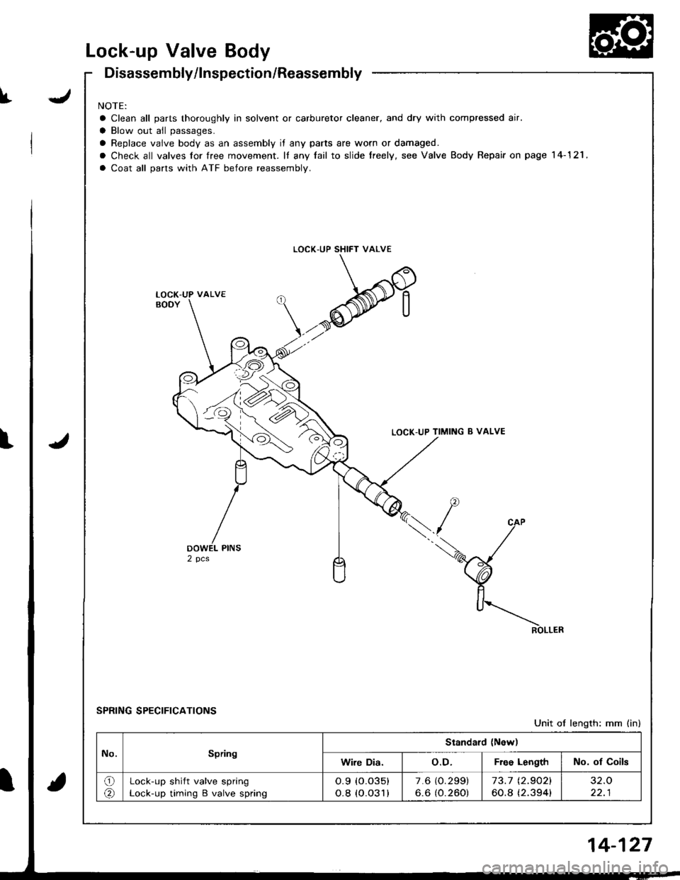
Lock-up Valve Body
JI
Disassembly/lnspection/Reassembly
NOTE:
a Clean all parts thoroughly in solvent or carburetor cleaner, and dry with compressed air.
a Blow out all passages.
a Replace vaive body as an assembly if any parts are worn or damaged.
o Check all valves for free movement. lf any fail to slide freely, see Valve Body Repair on page 14-121 ,
a Coat all parts with ATF before reassembly.
LOCK-UP SHIFT VALVE
LOCK-UP TIMING B VALVE
SPRING SPECIFICATIONS
Unit of length: mm (in)
LOCK-UP VALVE
No.Spring
Standard (New)
Wire Dia.o.D.Free LengthNo. of Coils
o(r\Lock-up shift valve spring
Lock-up timing B valve spring
o.9 (o.o35)
o.8 (o.o31)
7.6 (O.299)
6.6 (O.260)73.7 t2.9021
60.8 {2.394}
32.O
22.1
4-127
Page 545 of 1681
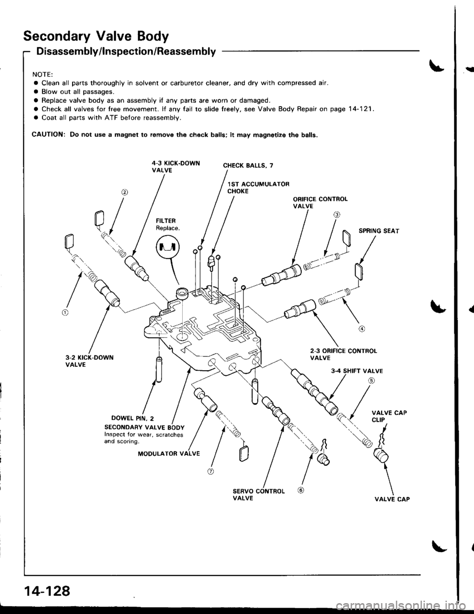
Secondary Valve Body
Disassembly/lnspection/Reassembly
NOTE:
a Clean all parts thoroughly in solvent or carburetor cleaner. and dry with compressed air.
a Blow out all passages.
a Replace valve body as an assembly if any parts are worn or damaged.
a Check all valves for tree movement. lf any fail to slide freely. see Valve Body Repair on page 14-121.
a Coat all parts with ATF belore reassembly.
CAUTION: Do not use a magnet to remove the check balls; it may magnetize the balls.
ORIFICE CONTROLVALVE
2-3 ORIFICE CONTROLVALVE
DOWEL PIN, 2
@
a/\.^fl*..'a
tio.
16
FILTERReplace.
o
\
SECONDARY VALVE BODYInspect for wear, scratchesand sconng.
4 SHIFT VALVE
/i
( / ;fl'J'*'
tq, fr
b
\
\VALVE CAP
l"
@
\
)
@
da')
aMODULATOR VALVE
14-128
i
{
Page 546 of 1681
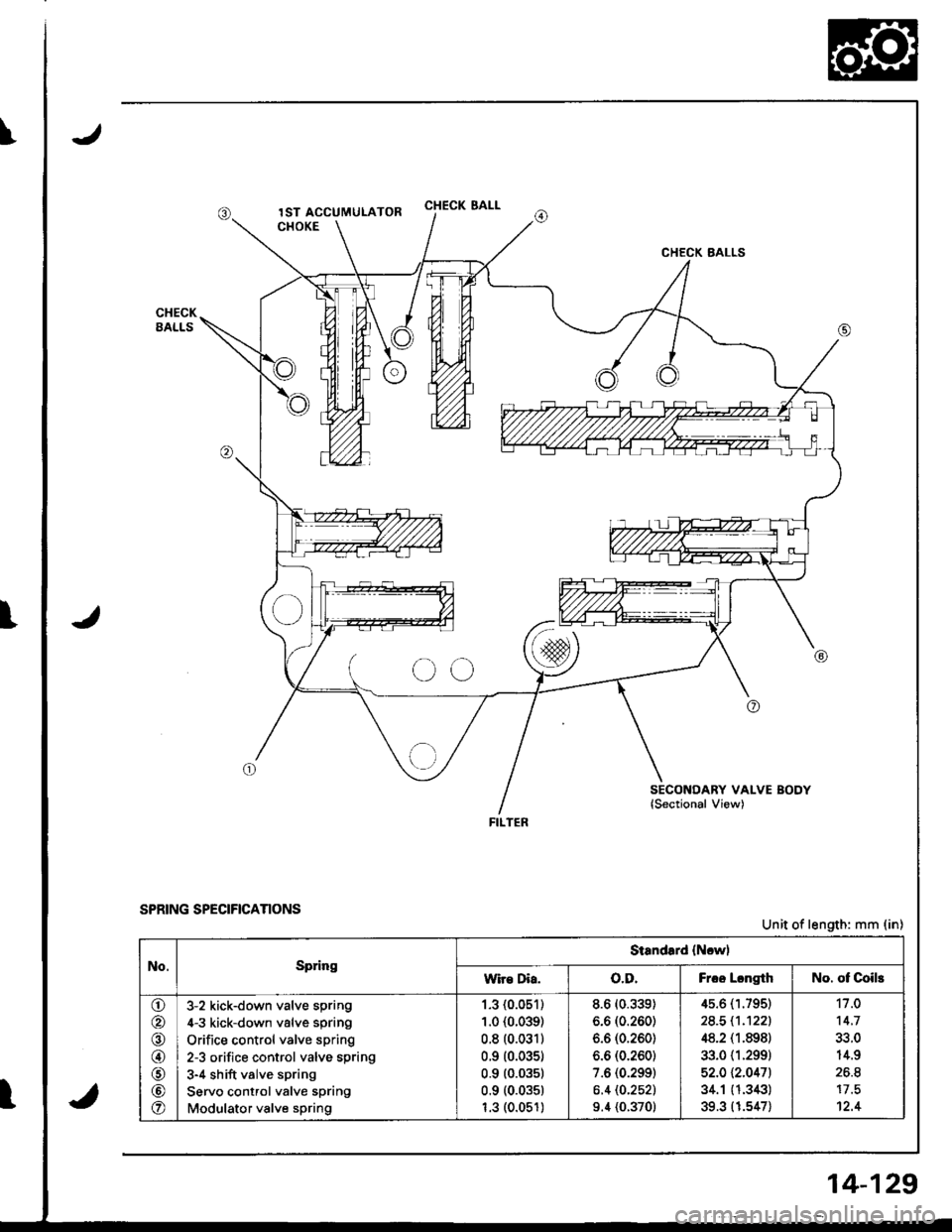
CHECK SALL
CHECK BALLS
SECONDARY VALVE BODYlSectional View)
FILTER
SPRING SPECIFrcANONSUnit of length: mm (in)
No.SpringStandard {Ncwl
wir€ Dia.o.D.Frcc LcngthNo. of Coils
\!-/
o
@
@
o
@
o
3-2 kick-down valve spring
4-3 kick-down valve spring
Orifice control valve spring
2-3 orifice control valve spring
3-4 shift valve spring
Servo control valve spring
Modulator valve spring
1.3 (0.051)
1.0 {0.039)
0.8 (0.031)
0.9 (0.035)
0.9 (0.03s1
0.9 (0.035)
1.3 (0.051)
8.6 (0.339)
6.6 (0.260)
6.6 (0.260)
6.6 (0.260)
7.6 (0.299)
6.4 (0.252)
9.4 (0.370)
4s.6 (1.795)
24.5 11.'t221
48.2 (1.898)
33.0 {1.299)
52.0 \2.0471
34.1 (1.343)
39.3 (1.547)
11 .0
14.7
14.9
26.8
12.4
14-129
Page 547 of 1681
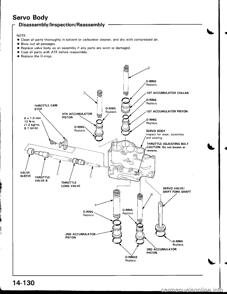
Servo Body
6 x 1.O mm12 N.m{1.2 kgf'm,8.7 tbt.ftl
Disassembly/lnspection/Reassembly
NOTE:
a Clean all parts thoroughly in solvent or carburetor cleaner, and dry with compressed air.
a Blow out all passages.
a Replace valve body as an assembly if any parts are worn or damaged.
a Coat all parts with ATF before reassembly.
a Replace the O-rings.
\9
\l
ll
1ST ACCUMULATOR COLLAR
O.RINGReplace.
1ST ACCUMUI.ATOR PISTON4TH ACCUMULATORPISTON
O.RINGReplace.
Replace.
SERVO BODYInspect for wear, scratchesand sconng.
THROTTLE ADJUSTING BOLTCAUTION: Do not loosen or
VALVE B
--'-'a@':
lll
li
il
14-130
Replace.
{
{a
Page 548 of 1681
I
t
t
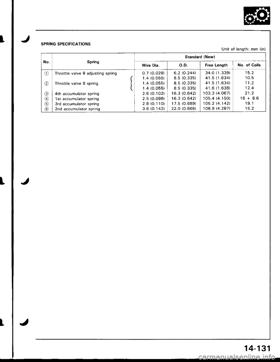
JSPRING SPECIFICATIONS
J
Unit of length: mm (in)
No.Spring
Standard {Newl
Wire Dia.o.D.Free LengthNo. of Coils
o
(r\
o
@
Throttle valve B adjusting spring
Throttle valve B spring I(
4th accumulator spring
1st accumulator spring
3rd accumulator spring
2nd accumulator spring
0.7 10.028)
1.4 {0.055)
1.4 (O.055)
1.4 (0.055)
2.6 (0. r 02)
2.5 (O.098)
2.8 (O.1 10)
3.6 (O.142)
6.2
8.5
8.5
8.5
I o_J
I o.J
17 .5
22.O
"o.244\
1o.33 5)
10.33 5)
1o.33 5)
lo.642)
lo.6421
10.68 9)
lo.866)
34.0 (1.339)
41.5 (1.634)
41.5 (1.634)
41.6 ('1 .638)
103.3 (4.067)
1 05.4 (4. 1 50)
105.2 l'4.142)
108.9 (4.287)
10.5
11.2
12.4
21.2
16 + 8.6
19.1
J
14-131
Page 549 of 1681
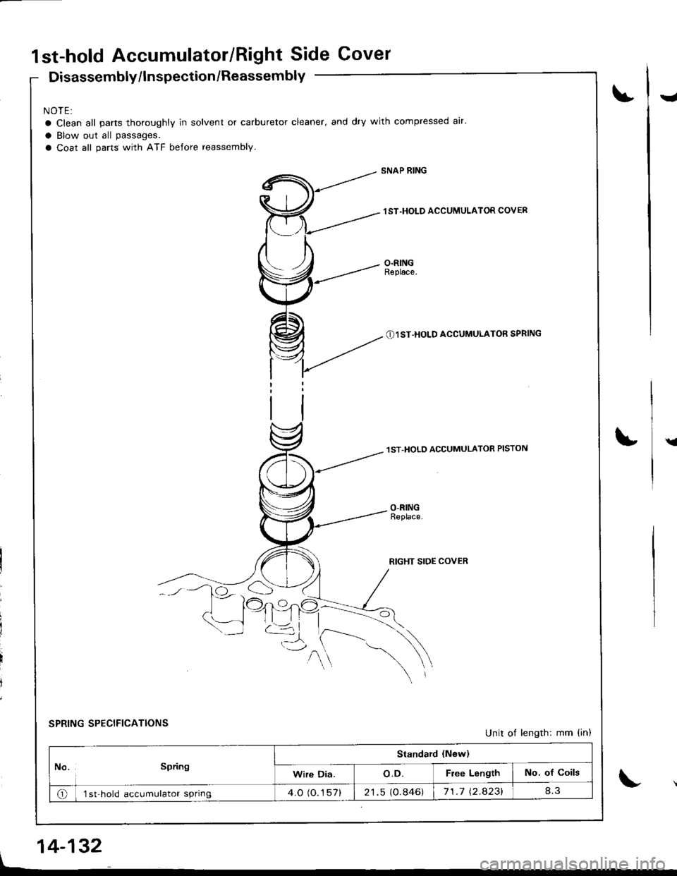
1st-hold Accumulator/Right Side Cover
Disassembly/lnspection /Reassembly
NOTE:
a Clean all parts thoroughly ln solvent or carburetor cleaner, and dry with compressed air.
a Blow out all passages.
a Coat all parts with ATF before reassembly.
rl
SNAP RING
lST.HOLD ACCUMULATOR COVER
O.RINGRephce.
(N1 ST-HOLD ACCUMULATOR SPRING
lST.HOLO ACCUMULATOR PISTON
RIGHT SIDE COVER
ra
\
SPRING SPECIFICATIONS
O
--l
Unit of length: mm {in)
No. Spring
Standard {New}
Wire Dia.o.D.Free LengthNo. of coils
o'lst hold accumulator spring4.O (O.1 57)21.5 (O.846)71.7 t2.a23l
L
14-132
Page 550 of 1681
\
\
\
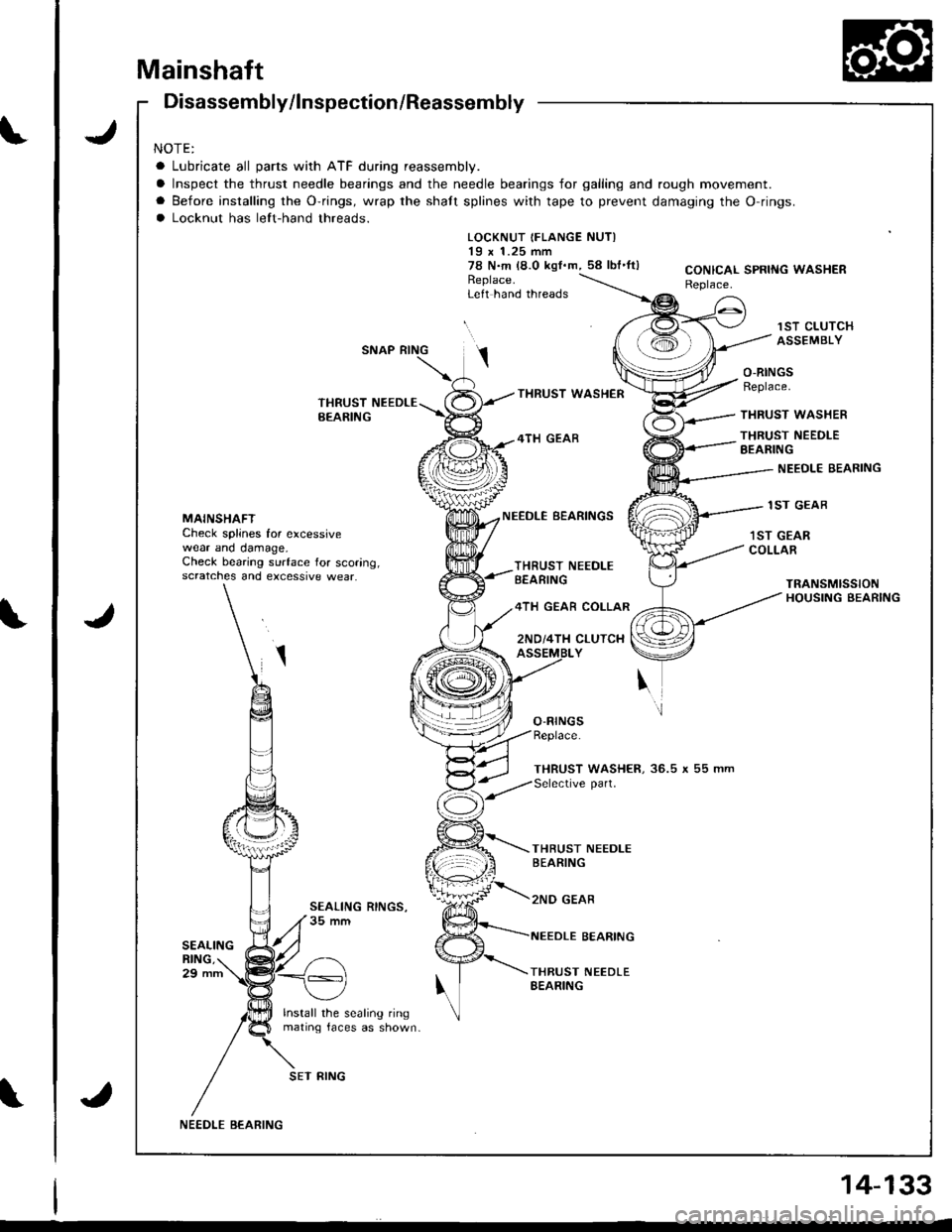
Mainshaft
J
J
Disassembly/lnspection/Reassembly
NOTE:
a Lubricate all parts with ATF during reassembly.
a Inspect the thrust needle bearings and the needle bearings for galling and rough movement.
a Before installing the O-rings, wrap the shatt splines with tape to prevent damaging the O-rings.
a Locknut has left-hand threads.
LOCKNUT IFLANGE NUTI19 x 1.25 mm78 N.m (a.0 kgf.m, 58 lbl'ltlReplace.Left hand threads
THRUST WASI{€R
4TH GEAR
CONICAL SPRING WASHERReplace.
1ST CLUTCHASSEMBLY
O-RINGSReplace.
THRUST WASHER
THRUST NEEDLEEEARING
NEEDLE EEARING
1ST GEABMAINSHAFTCheck splines for excessivewear ano oamage,Check bearing surface for scoring,scratches and excessive wear.
NEEDLE BEARINGS
THRUST NEEDI-EBEARING
4TH GEAR COLLAR
2ND/4TH CLUTCH
BEARING
THRUST NEEDLEBEARING
lST GEARCOLLAR
O-RINGSReplace.
THRUST WASHER, 36.5 x 55 mmSelective part.
THBUST NEEDLEBEARING
2ND GEAR
lnstall the sealing ringmating laces as shown-
SET FING
NE€DLE BEARING
J
14-133