HONDA INTEGRA 1998 4.G Workshop Manual
INTEGRA 1998 4.G
HONDA
HONDA
https://www.carmanualsonline.info/img/13/6069/w960_6069-0.png
HONDA INTEGRA 1998 4.G Workshop Manual
Trending: seats, sunroof, immobilizer, tow bar, lock, ECO mode, CD changer
Page 561 of 1681
Sub-shaft Bearings
Replacement
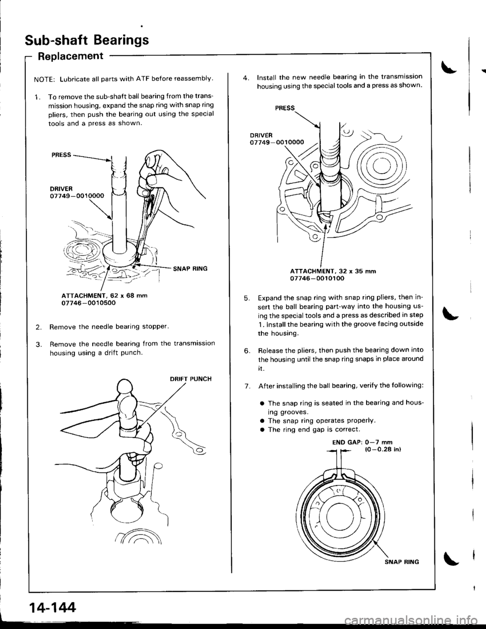
NOTE: Lubricate all parts with ATF before reassembly.
1 . To remove the sub-shaft ball bearing from the trans-
mission housing, expand the snap ring with snap ring
pliers, then push the bearing out using the special
tools and a press as shown.
ATTACHMENT. 62 r 68 mm07746-0010500
Remove the needle bearing stopper.
Remove the needle bearing from the transmission
housing using a drift punch.
DRIFT PUNCH
L
14-144
7A
SNAP RING
Install the new needle bearing in the transmission
housing using the specialtools and a press as shown.
PRESS
ATTACHMENT, 32 x 35 mm07746-0010roo
Expand the snap ring with snap ring pliers, then in-
sert the ball bearing part-way into the housing us-
ing the special tools and a press as described in step
1. Installthe bearing with the groove facing outside
the housing.
Release the pliers, then push the bearing down into
the housing until the snap ring snaps in place around
rt.
After installing the ball bearing, verity the following:
a The snap ring is sealed in the bearing and hous-
ing grooves.
a The snap ring operates Properly.a The ring end gap is correct.
5.
6.
7.
END GAP: 0-7 mm
Page 562 of 1681
I
\
T
Clutch
lllustrated Index
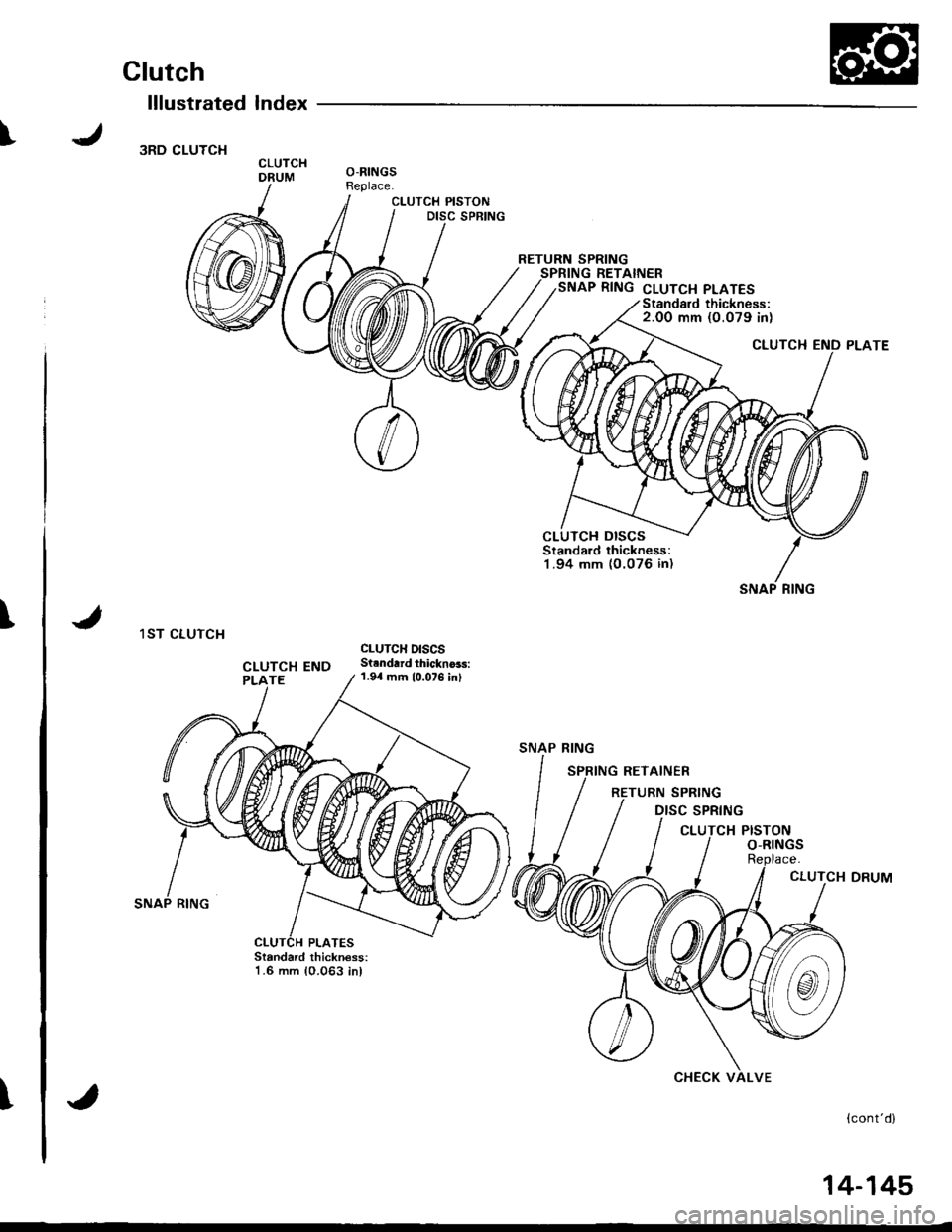
3RD CLUTCH
1ST CLUTCH
CLUTCH PISTONDISC SPRING
CLUTCHDRUMO-RINGSReplace.
RETURN SPRINGSPRING RETAINERSNAP RING cLUTcH PLATES
Standard thickness:1.6 mm 10.063 inl
{cont'd}
CLUTCH DISCSStandard thickness:1 .94 mm (O.076 in)
SNAP RING
CLUTCH END
SNAP RING
SPRING
CHECK VALVE
14-145�
Page 563 of 1681
Glutch
lllustrated lndex
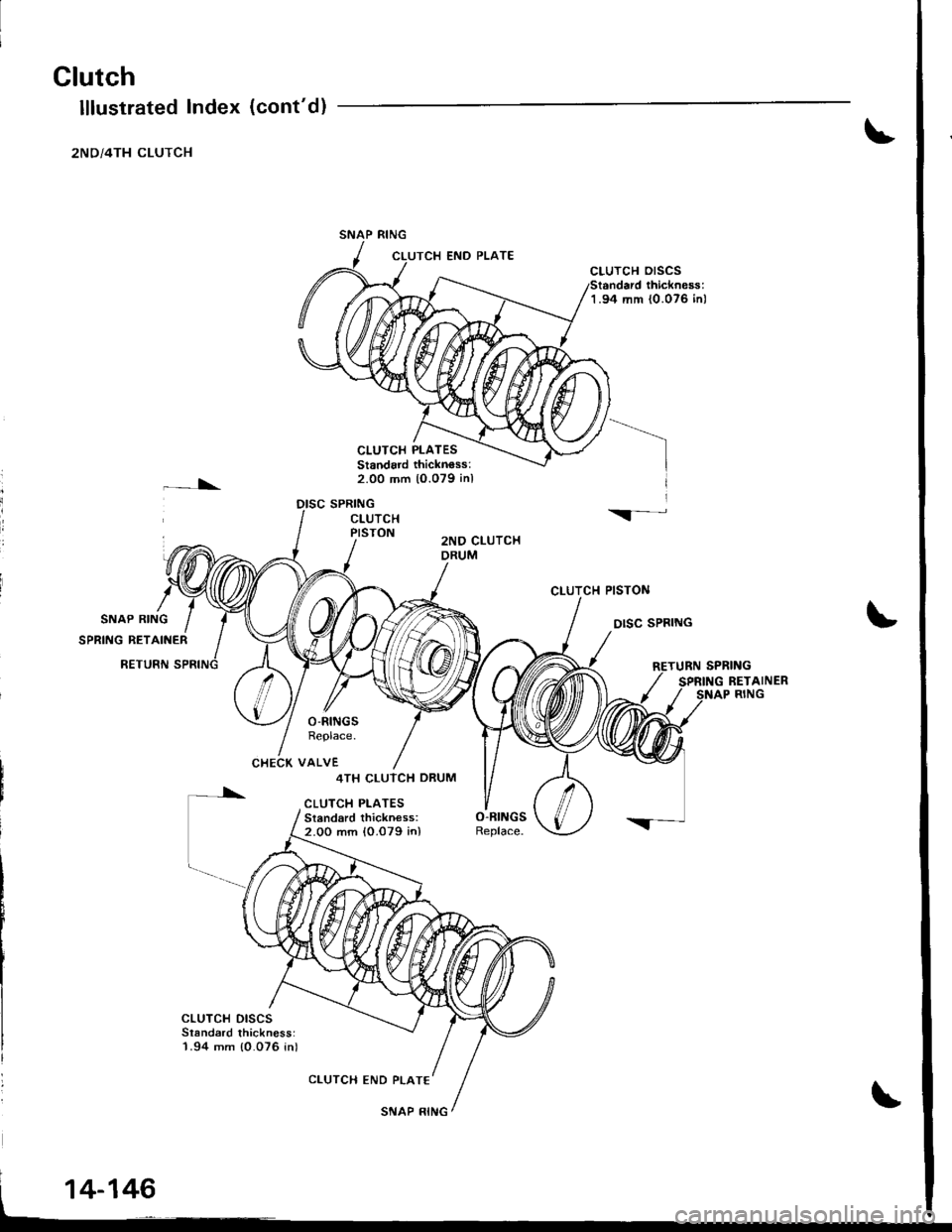
2ND/4TH CLUTCH
\
CLUTCH PLATESStandard thicknoss:2.00 mm 10.079 inl
DISC SPRING
CLUTCH OrSCS
1.94 rr|m {0.076 inl
CLUTCTI PISTON
DISC SPBING
(cont'd)
END PLATE
I
il
\-CLUTCHPISTON2NO CLUTCHDRUM
O-RINGSReplace.
CHECK VALVE
[*
cLuTcH DrscsSlandard thickness:1.94 mm {0.076 in)
4TH CLUTCH DRUM
CLUTCH PLATESSi.ndard thickness:2.00 mm {0.079 in)
CLUTCH END PLATE
14-146
SNAP RING
Page 564 of 1681
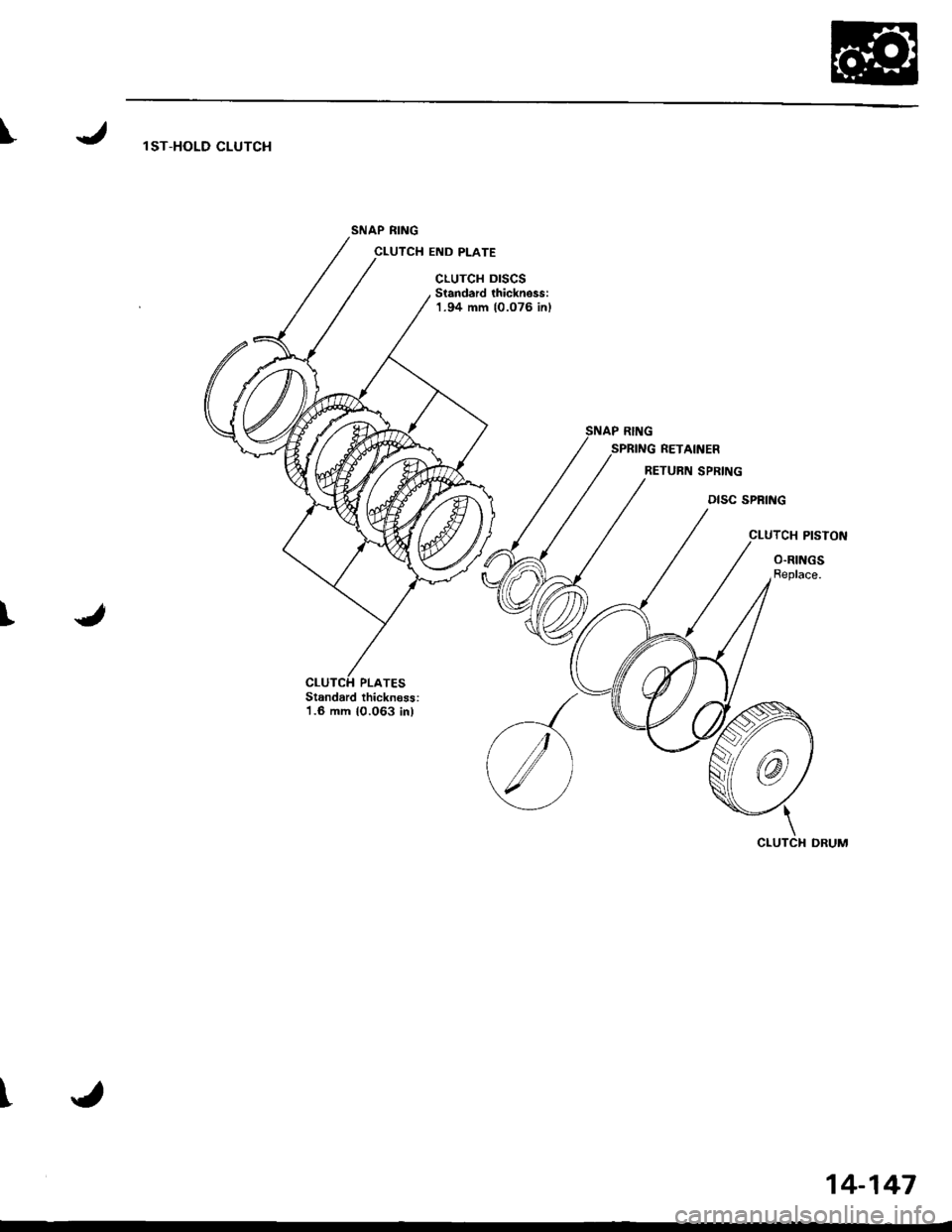
\l ST-HOLD CLUTCH
SNAP RING
CLUTCH END PLATE
cLuTcH DrscsStandard thickness:1.94 mm {0.076 inl
SPRING RETAINER
RETURN SPRING
DISC SPRING
CLUTCH PISTON
O.RINGSReplace.
t
Standard thicknoss:1.6 mm 10.063 in)
l'
14-147
Page 565 of 1681
Clutch
!
Disassembly
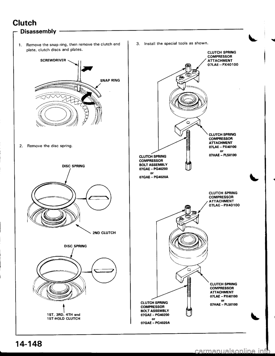
1. Remove the snap ring, then remove the clutch end
olate, clutch discs and Plates
SCREWDRIVER
SNAP RING
2. Remove the disc spring.
2ND CLUTCH
I
I'tsT, 3RO, 4TH andlST.HOLD CLUTCH
DISC SPRING
DISC SPRING
14-148
3. Install the special tools as shown.
CLU'CH SPRINGCOMPRESSORBOLT ASSEMBLY07GAE - PG,O200olO'GAE - PG4I}2OA
CI-UTCH SPRINGCOMPRESSORBOLT ASSEMBLY07GAE - PG40200otOTGAE - PG4O2OA
CLUTCH SPRINGCOMPRESSORATTACHMENT07LAE -PX40100
CLUTC}I SPRINGCOMPRESSORATTACHMENT07LAE - PX0100ot07HAE - P150100
CLUTCH SPRINGCOMPRESSORATTACHMENT07LAE-PX40100
CLUTCH SPRINGCOMPRESSORATTACHMENT07LAE - PX(}Iq)ol07HAE - P150100
Page 566 of 1681
I
T
)
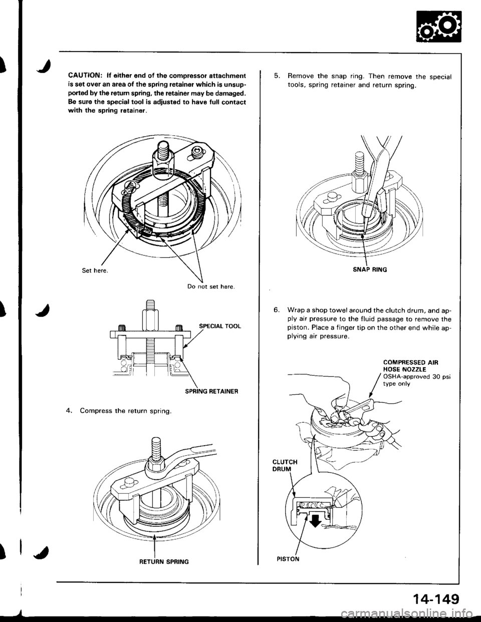
CAUTION: lf either end of the comoressor attachment
is set over an area of the spring letainsr which is unsup-
portod by the retum spring, the retainer may be damaged.
Be sur6 the special tool is adiusted to have full contact
with the spring ietainel,
RETAINER
4. Compress the return spring.
Do not set here.
RETURN SPRING
)
14-149
5.Remove the snap ring. Then remove the specialtools, spring retainer and return spring.
Wrap a shop towelaround the clutch drum, and ap-ply air pressure to the fluid passage to remove thepiston. Place a finger tip on the other end while ap,plying air pressure.
COMPRESSED AIRHOSE NOZZLEOSHA-approved 30 psi
CLUTCH
SNAP RING
PISTON
Page 567 of 1681
Glutch
Reassembly
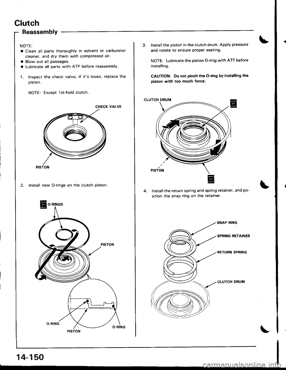
NOTE:
a Clean all parts thoroughly in solvent or carburetor
cleaner, and dry them with compressed alr.
a Blow out all passages.
a Lubricate all parts with ATF belore reassembly.
1. Inspect the check valve; if it's loose, replace the
prston.
NOTE: Except 1sr-hold clutch
CHECK VALVE
PISTON
14-150
3. Installthe Diston in the clutch drum. Apply pressure
and rotate to ensure proper seating.
NOTE: Lubricate the piston O-ring with ATF before
installing.
CAUTION: Do not pinch tho O-ring by installing the
piston with too much force'
CLUTCH DRUM
Installthe return spring and spring retainer. and po-
sition the snap ring on the retaine..
CLUTCH DRUM
Page 568 of 1681
I
t
I
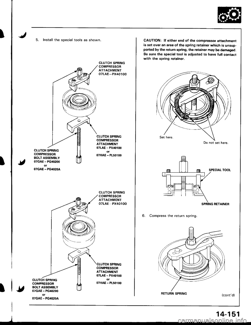
5. Install the sDecial tools as shown.
CLUTCH SPRINGCOMPRESSORBOLT ASSEMBLY07GAE - PG40200olOTGAE - PG4.I'zOA
CLUTCH SPRINGCOMPRESSORBOLT ASSEMBLY07GAE - PG40200
OTGAE - PGIO2OA
CLUTCH SPRINGCOMPRESSORATTACHMENToTLAE -PX40100
CLUTCH SPRINGCOMPRESSORATIACHMENT07LAE - PX40100o107HAE - PL50100
CLUTCH SPRINGCOMPRESSORATTACHMENTOTLAE PX4OlOO
SPRINGCOMPRESSORATTACHMENT07LAE - PX40100ol07HAE - PL50100
l
CAUTION: lf either end of th6 compreaso. attachmentis set over an area of the spring lstainer which is unsuo-ported by the retum spring, the retainer may b€ damaged.Be su?e the special tool is adiusted to have full contacrwith the spring retainer.
SPECIAL TOOL
RETAINER
6. Compress the return spring.
Do not set here.
RETURN SPRING
14-151
Page 569 of 1681
Clutch
Reassembly {cont'd)
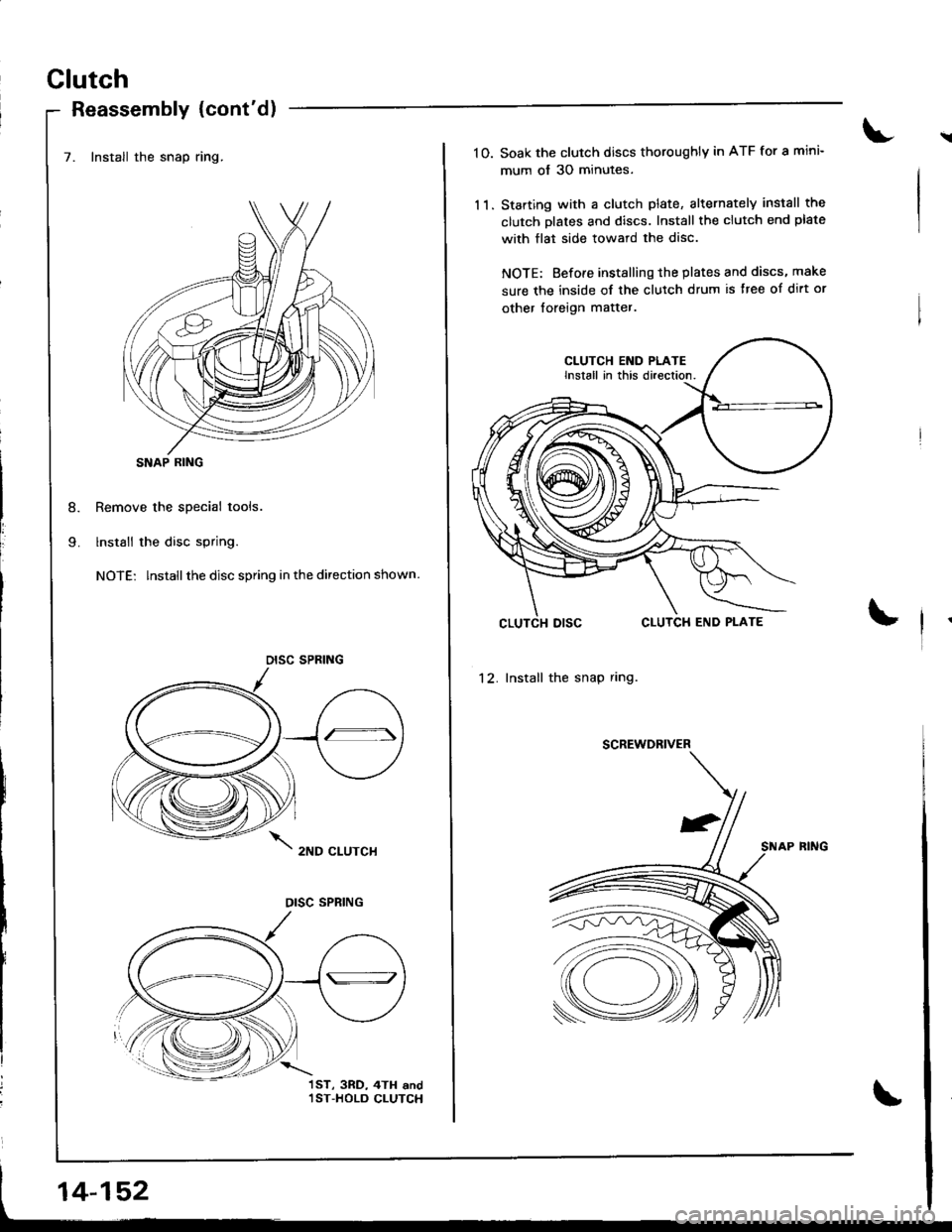
7. Install the snap ring.
Remove the special tools.
lnstall the disc spring.
NOTE: lnstallthe disc spring in the direction shown.
2ND CLUTCH
j
I
SNAP RING
DISC SPRING
OISC SPRING
1ST, 3RD, 4TH and,IST-HOLD CLUTCH
14-152
\10. Soak the clutch discs thoroughly in ATF for a mini-
mum of 30 minutes.
11. Starting with a clutch plate, alternatelY install the
clutch Dlates and discs. Install the clutch end plate
with flat side toward the disc.
NOTE: Before installinq the plates and discs, make
sure the inside of the clutch drum is ttee of dirt or
other loreign matter.
CLUTCH END PLATEInstall in this direction.
12. Install the snap ring.
SCREWDRIVER
SNAP FING
Page 570 of 1681
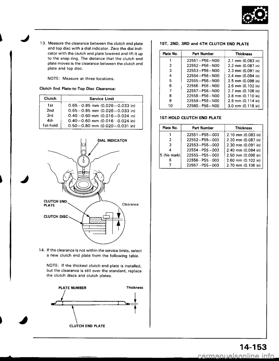
1 3. Measure the clearance between the clutch end olate
and top disc with a dial indicator. Zero the dial indi-
cator with the clutch end plate lowered and lift it up
to the snap ring. The distance that the clutch endplate moves is the clearance between the clutch endplate and top disc.
NOTEi Measure at three locations.
Clutch End Plate-to-ToD Disc Clearance:
1 4. lf the clearance is not within the service limits, selecta new clutch end plate from the following table.
NOTE: lf the thickest clutch end plate is installed,but the clearance is still over the standard. replacethe clutch discs and clutch plates.
PLATE NUMEERThickness
ClutchSeNice Limit
lst
2nd
3rd
4th
l st-hold
O.65 -O.85 mm (0.026-O.033 inl
O.65-0.85 mm (0.026 - 0.033 in)
O.40-0.60 mm {O.016-O.O24 in)
O.40-0.60 mm (O.O16 O.O24 in\
O.5O-O.8O mm (O.O2O-O.O31 in)
CLUTCX ENO PLATE
14-153
1ST, 2ND, 3RD and 4TH CLUTCH END PLATE
.lST.HOLD CLUTCH END PLATE
Plate No.Pan Numb€rThickn6ss
I
2
3
4
5
6
7
8
I
10
22551-P56-N00
22552,P56-N00
22553-P56-N00
22554-P56 -N00
22555 -P56- N00
22556 P56 -N00
22557 -P56 - N00
22558 P56-N00
22559-P56-N00
22560-P56- N00
2.1 mm (0.083 in)
2.2 mm (0.087 in)
2.3 mm {0.091 in)
2.4 mm (0.094 in)
2.5 mm (0.098 in)
2.6 mm {0.102 in)
2.7 mm i0.106 in)
2.8 mm (0. 1 10 in)
2.9 mm {0.114 in)
3.0 mm {0.1 18 in)
Plate No.Pan NumborThickness
I
2
3
4
5 (No mark)
6
7
22551-PS5-003
22552 - PS5-003
22553- PS5,003
22554- PS5 -003
22555 PS5-003
22556-PSs 003
22557- PS5-003
2.10 mm (0.083 in)
2.20 mm (0.087 inl
2.30 mm {0.091 in)
2.40 mm {0.094 in)
2.50 mm (0.098 in)
2.60 mm (0.102 in)
2.70 mm (0. 106 in)
Trending: fuel pressure, light, oil temperature, child seat, Ground location, oil dipstick, ZC engine

