HONDA INTEGRA 1998 4.G Workshop Manual
Manufacturer: HONDA, Model Year: 1998, Model line: INTEGRA, Model: HONDA INTEGRA 1998 4.GPages: 1681, PDF Size: 54.22 MB
Page 531 of 1681
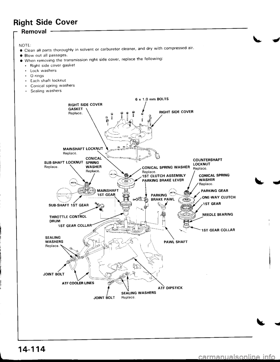
Right Side Cover
Removal
NOTE:
a Clean all parts thoroughly in solvent or carburetor cleaner' and dry with compressed alr'
a Blow out all Passages.
a When removing the transmission right side cover, replace the following:
. Right side cover gasket
. Lock washers. O rings. Each sha{t locknut
. Conical spring washers
. Sealing washers
RIGHT SIDE COVER
GASKETBeplace.
J
mm BOLTS6x1.0
,c
B,
MAINSHAFTReplace.LOCKNUT
RIGHT SIDE COVER
CONICAL SPRING WASHER
COUNTERSHAFTLOCKNUTSUB-SHAFT LOCKNUTReplace.
CONICALSPRINGWASHERReplace.Replace.1ST CLUTCH ASSEMBLY
PARKING BRAKE LEVERCONICALWASHERReplace.
SPRING
J
\-_7
SUB-SHAFT 1
PARKING GEAR
ONE-WAY CLUTCH
1ST GEAR
NEEOLE BEARING
1ST GEAR COLLAR
SEALINGWASHERSReplace.
JOINT BOLT
otPsTtcK
SEALING WASHERSReplace.
t
'::-Pf.a
THROTTLE CONTROLDRUM
1ST GEAB
ATF COOLER LINES
'. .)
14-114
I
Page 532 of 1681
I
t
I
1.
2.
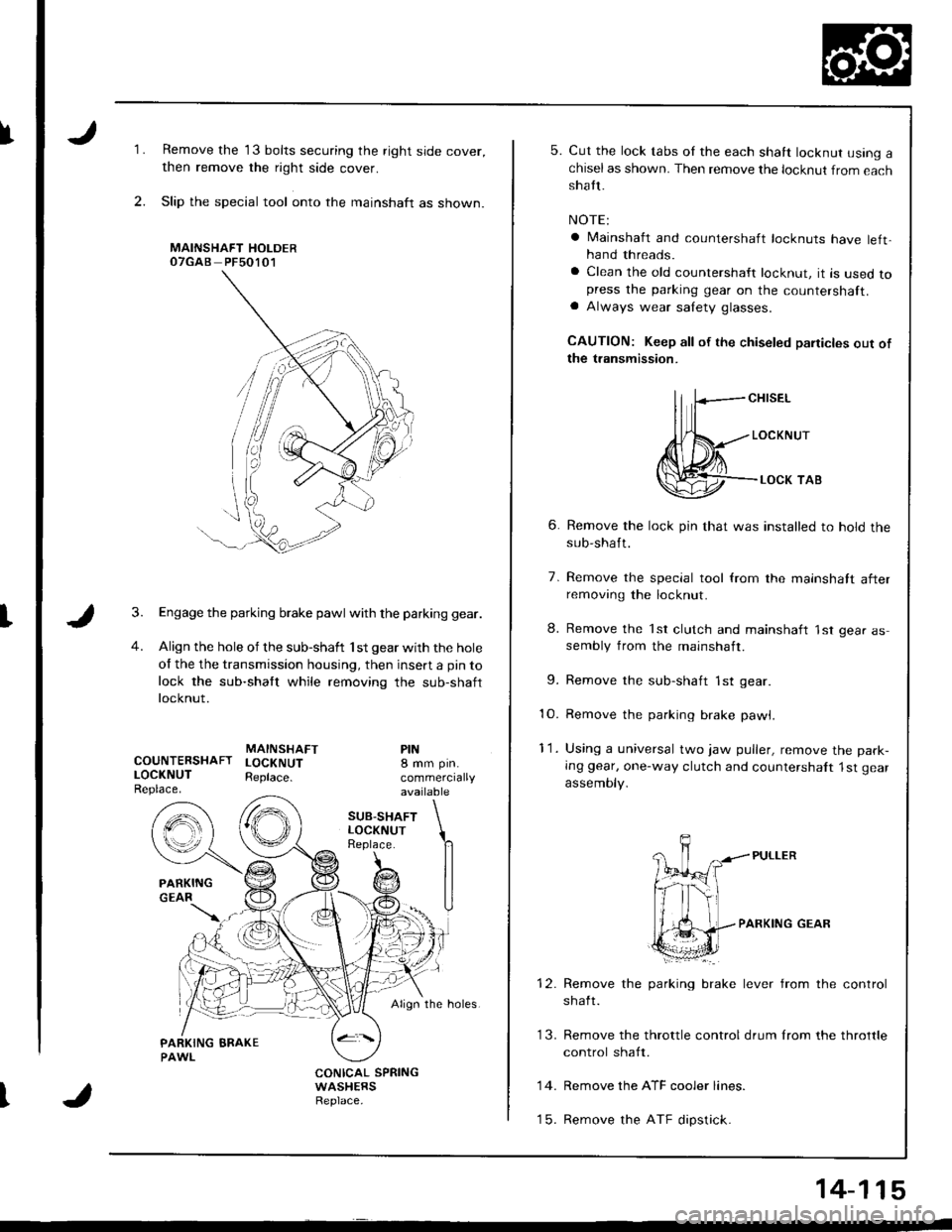
Remove the 13 bolts securing the right side cover,
then remove the right side cover.
Slip the special tool onto the mainshaft as shown.
MAINSHAFT HOLDEROTGAB PFsO1O1
Engage the parking brake pawl with the parking gear.
Align the hole of the sub-shaft 'lst gear with the hole
of the the transmission housing, then insert a pin to
lock the sub-shaft while removing the sub-shaft
locknut.
MAINSHAFTCOUNTERSHAFT LOCKNUTLOCKNUT Reptace.Replace.
PIN8 mm pin.
commerciallyavailable
SUB.SHAFTLOCKNUTReplace.
Align the holes.
CONICAL SPRINGWASHERSReplace.
5. Cut the lock tabs oI the each shaft locknut using achiselas shown. Then remove the locknut from eachshatt.
NOTE:
a lvlainshaft and countershaft locknuts have left,hand threads.
a Clean the old countershaft locknut, it is used topress the parking gear on the countershaft.a Always wear salety glasses.
CAUTION: Keep all of the chiseled paiticles out ofthe transmission.
ll fcH,sEL
Jl{*---,o"*",r
@--.**,o,
6. Remove the lock pin that was installed to hold thesub-shaft.
7. Remove the special tool from the mainshatt afterremoving the locknut.
8. Remove the 'lst clutch and mainshaft 'lst gear assembly from the mainshaft.
9. Remove the sub-shaft 1st gear
10. Remove the parking brake pawl,
11. Using a universal two jaw puller, remove the park-
Ing gear, one-way clutch and countershalt 1st gear
assemoty.
PARKING GEAR
brake lever from the controlRemove the parking
shaft.
Remove the ATF cooler lines.
Remove the ATF dipstick.
13. Remove the throttle control drum lrom the throttle
control shaft.
14.
t5.
14-115
Page 533 of 1681
Transmission Housing
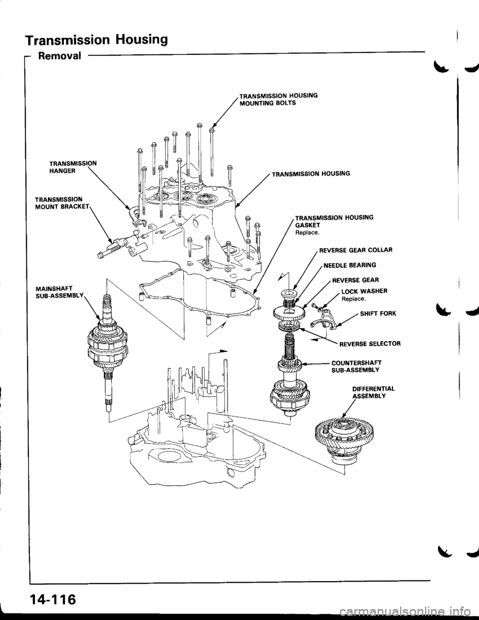
Removal
J
TRANSMISSION HOUSING
MOUNTING BOLTS
TRANSMISSION HOUSING
TRANSMISSION HOUSING
GASKETReplace.
REVERSE GEAR COLLAB
NEEDLE BEARING
REVERSE GEAR
MAINSHAFTSU8-ASSEMBLY
, 14-116
LOCX WASITEFReplace.
4
REVERSE SELECTOR
COUNTERSHAFTSUB.ASSEMELY
DIFFERENTIALASSEMBLY
J
Page 534 of 1681
fNOTE:
a Clean all parts thoroughly in solvent or carburetor
cleaner and dry with compressed air.a Blow out all passages.
a When removing the transmission housing, replace the
tollowing:. Transmission housing gasket. Lock washer
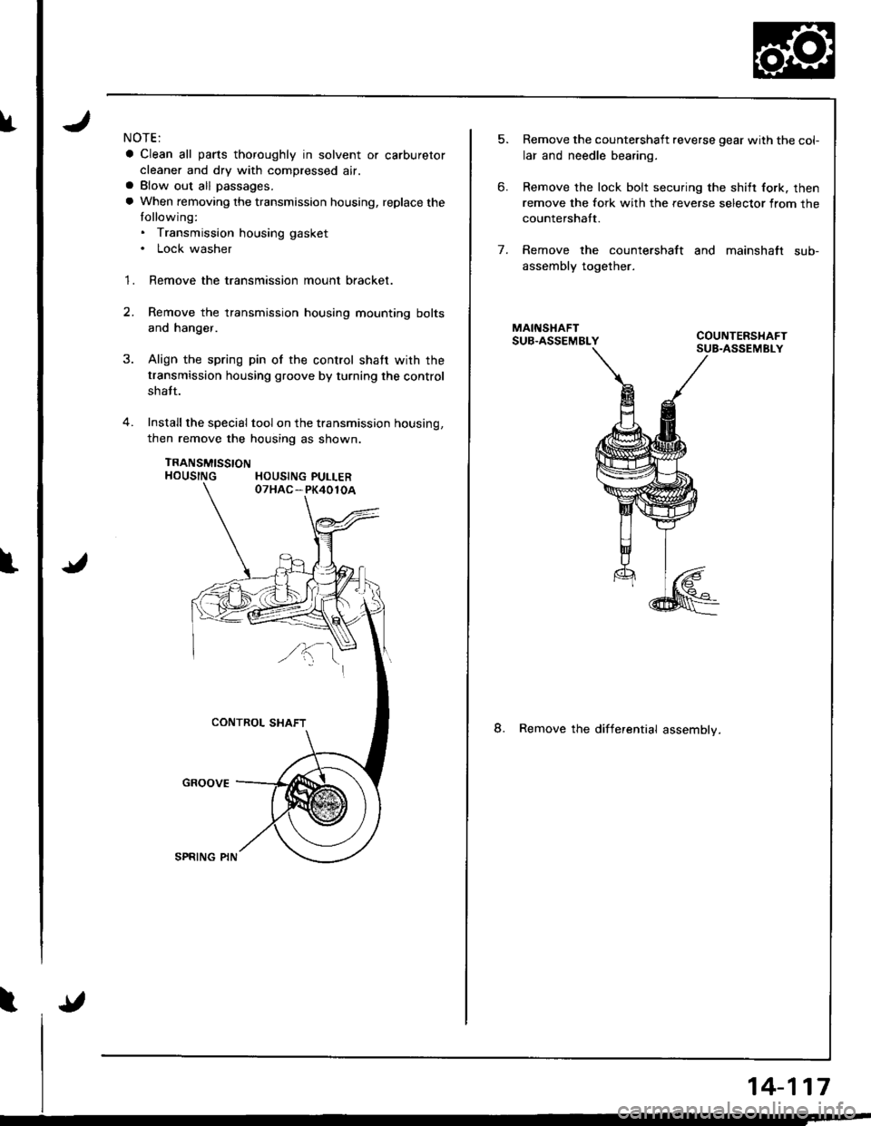
1. Remove the transmission mount bracket.
2.Remove the transmission housing mounting bolts
and hanger.
Align the spring pin of the control shatr wirh the
transmission housing groove by turning the control
shatt.
Install the special tool on the transmission housing,
then remove the housing as shown.
TRANSMISSTONHOUSING HOUSING PULLER
5.
6.
Remove the countershaft reverse gear with the col-
lar and needle bearing.
Remove the lock bolt securing the shilt fork. then
remove the fork with the reverse selector from the
countershatt.
Remove the countershaft and mainshaft sub-
assembly together.
8. Remove the differential assemblv.
7.
14-117
Page 535 of 1681
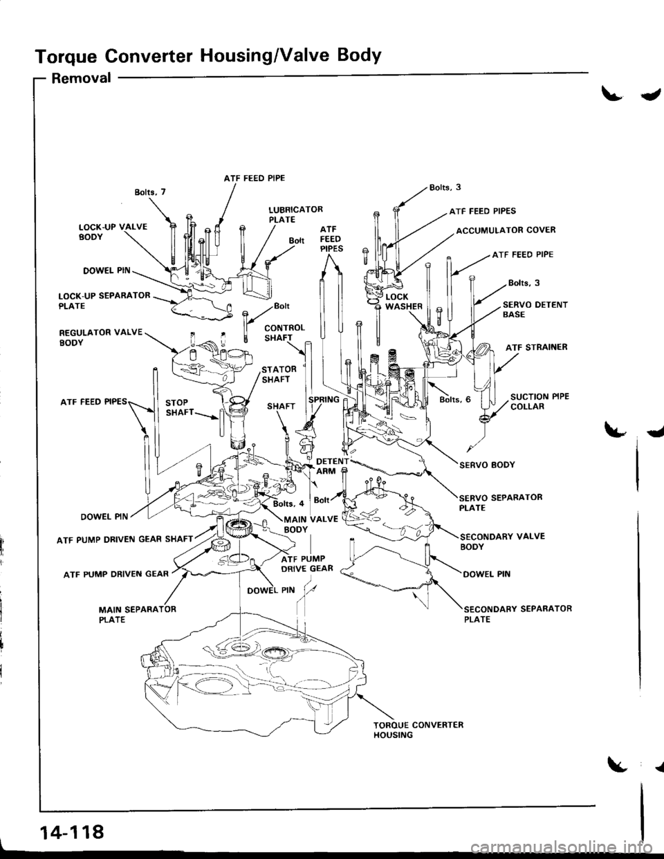
Torque Converter Housing/Valve Body
Removal
t
LUBRICATORPLATEATF FEED PIPES
ACCUMULATOR COVER
ATF FEEO PIPE
Bolrs,3
ATF
Bott FEEDPIPES
DOW€I- PIN
LOCK-UP SEPARATORPLATE
REGULATOR VALVEEODY
SERVO DETENTSASE
ATF STRAINER
LOCKWASHER
ATF FEED
DOWEL PIN
ATF PUMP DRIVEN GEAR SHAFT
ATF PUMP ORIVEN GEAR
-
SEPARATOR
.a
ATF FEED PIPE
, ./"o"
ll coNrRoL
E Sl{AF-r
ATOR
PLATE
_ro-rr!_
Page 536 of 1681
I
l"
I
J
NOTE:
a Clean all parts thoroughly in solvent or carburetor
cleaner and dry with compressed air.
a Blow out all passages.
a When removing the valve body replace the lollowing:. O-rings. Lock washers
1 . Remove the ATF feed pipes from the servo body, ser-vo detent base, accumulator cover, lock-up valve
body and main valve body.
2. Remove the three bolts securing the ATF strainer
and servo detent base, then remove the strainer
and detent base.
3. Remove the three bolts securing the accumulator
cover, then remove the accumulator cover.
4. Remove the six bolts securing the servo body. then
remove the servo body and separator plate.
5. Remove the one bolt securing the secondary valvebody, then remove lhe secondary valve body andseparator plate.
6. Remove the eight bolts securing the lubricator plate
and lock-up valve body, then remov€ th€ lubricator
plate. Iock-up valve body, and separator plate.
7. Remove the one bolt securing the regulator valve
body, then remove the regulator valve body.
8. Remove the stator shaft and stop shaft.
9. Remove the detent spring from the detent arm, then
remove the control shaft from the torque converter
housrng.
1O. Remove the detent arm and detent arm shatt from
the main valve body.
1 'l . Remove the four bolts securing the main valve body,
then remove the main valve body.
'I2. Remove the ATF pump driven gear shatt, then re-
move the ATF pump gears.
13. Remove the main separator plate with two dowel
pins.
15.
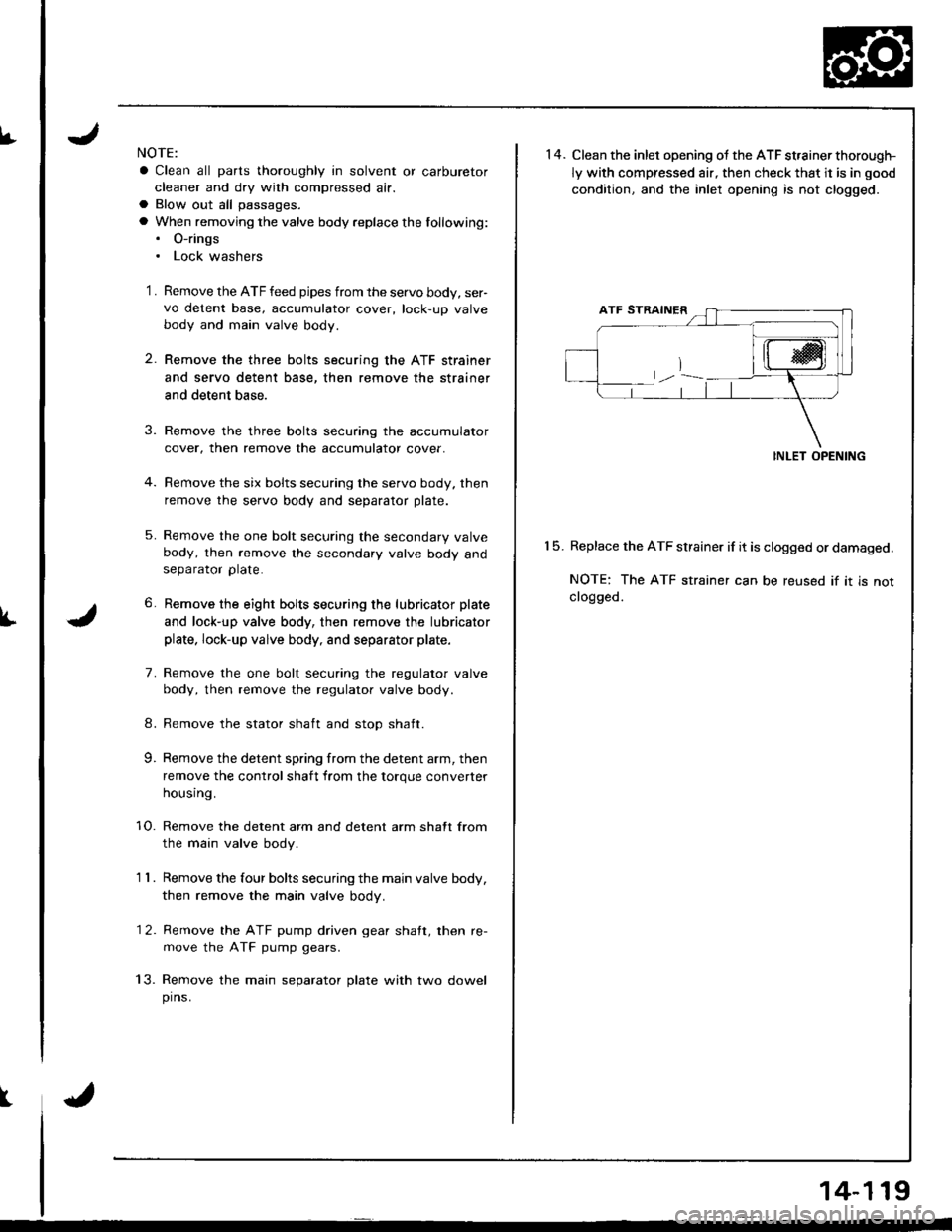
14. Clean the inlet opening ot the ATF st,ainer thorough-
ly with compressed air, then check that it is in good
condition. and the inlet opening is not clogged.
INLET OPENING
Replace the ATF strainer if it is clogged or damaged.
NOTE: The ATF strainer can be reused if it is notclogged.
14-119
Page 537 of 1681
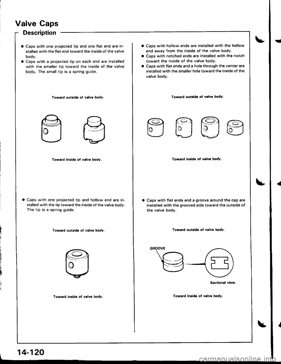
Valve Caps
Description
a Caps with one projected tip and one flat end are in-
stalled with the flat end toward the inside oJ the valve
body.
a Caps with a proiected tip on each end are installed
with the smaller tip toward the inside of the valve
body. The small tip is a spring guide.
Toward outsid6 ot v6lvo body.
Toward insido of valvo bodv.
Caps with one projected tip and hollow end are in-
stalled with the tip toward the inside of the valve body.
The tip is a spring guide.
Tow6.d outsid€ ot valvo bodY.
Tow6rd in3id6 ol valvo bodv.
, 14-120
CaDs with hollow ends are installed with the hollow
end away from the inside of the valve body.
Caps with notched ends are installed with the notch
toward the inside ot the valve body.
Caps with tlat ends and a hole through the center are
installed with the smaller hole toward the inside of the
valve body.
Toward ouGida ol valvo body.
Efla
Toward in.ldo ot valve bodY.
Caps with tlat ends and a groove around the cap are
installed with the grooved side toward the outside of
the valve bodv.
Toward oulrlda of valve bodv.
"-\"h
,a\
v{9
Sociiohal viow.
Toward insido ot v.lvo body.
I
{
Page 538 of 1681
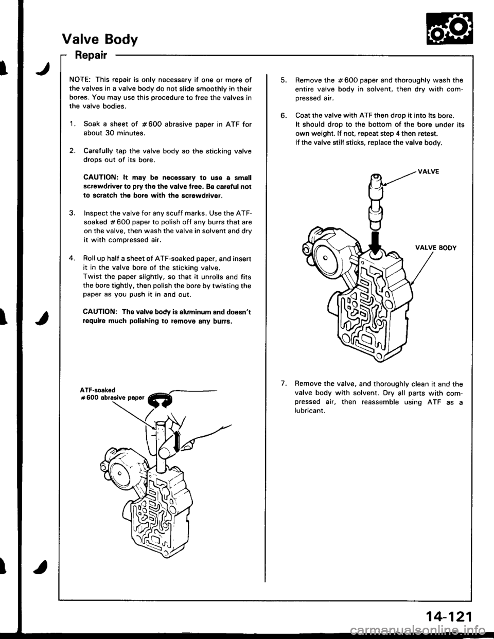
NOTE: This repair is only necessary if one or more of
the valves in a valve body do not slide smoothly in their
bores. You may use this procedure to free the valves in
the valve bodies.
1. Soak a sheet of # 600 abrasive DaDer in ATF for
about 30 minutes.
2. Caretully tap the valve body so the sticking valve
drops out of its bore.
CAUTION: lt may be necessary to use a small
scrawdriv6r to pry the the valve f.66. Bs caloful not
to sciatch th€ bole with th6 scrowdriver.
Remove the #600 paper and tho.oughly wash the
entire valve body in solvent, th€n dry with com-
pressed air.
Coat the valve with ATF then droD it into its bore.
It should droD to the bottom of the bore under its
own weight. lf not, repeat step 4 then retest.
lf the valve still sticks, replace the valve body.
InsDect the valve for anv scuff marks. Use the ATF-
soaked # 600 paper to polish ofl any burrs that are
on the valve. then wash the valve in solvent and drV
it with compressed air,
Roll up halt a sheet ot ATF-soaked paper, and insert
it in the valve bore of the sticking valve.
Twist the paper slightly, so that it unrolls and fits
the bore tightly. then polish the bore by twisting thepaper as you push it in and out.
CAUTION: The valvs body is aluminum and doesn't
require much polishing ro lomovo any bulla.
VALVE BODY
7.Remove the valve. and thoroughly clean it and the
valve body with solvent. Dry all parts with com-pressed air, then reassemble using ATF as alubricant.
Valve Body
Repair
14-121
Page 539 of 1681
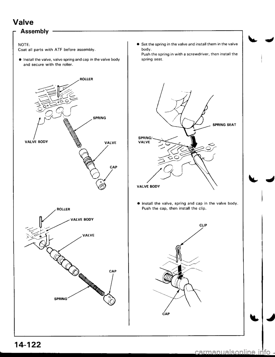
Valve
Assembly
NOTE:
Coat all parts with ATF before assembly.
a Install the valve, valve spring and cap in the valve body
and secure with the roller.
VALVE BODY
VALVE
14-122
Ia Set the spring in the valve and installthem in the valve
oooy.
Push the spring in with a screwdriver, then installthe
spnng seat.
SPRING SEAT
VALVE EODY
Install the valve, spring and cap in the valve body.
Push the cap, then install the clip.
Page 540 of 1681
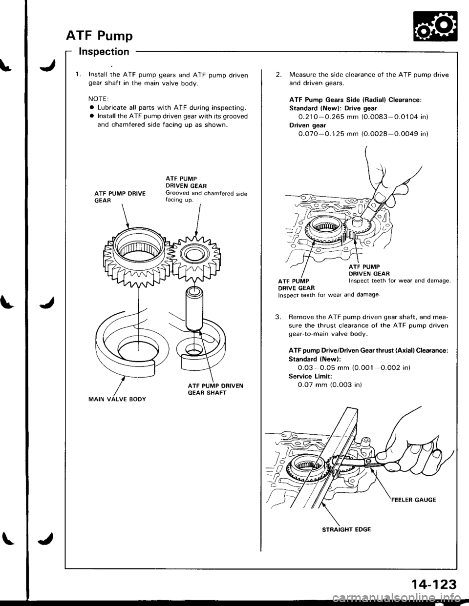
ATF Pump
Inspection
't.Install the ATF pump gears and ATF pump drivengear shaft in the main valve body.
NOTE:
a Lubricate all parts with ATF during inspecting.
a Installthe ATF pump driven gear with its grooved
and chamfered side facing up as shown.
2.Measure the side clearance of the ATF pump drive
and driven gears.
ATF Pump Gears Side {Radial} Clearance:
Standald (Newl: Drive geal
O.21O 0.265 mm (O.O083 O.O104 in)
Dfiven geal
0.07O 0.1 25 mm (O.O028 O.0049 in)
ATF PUMPDRIVEN GEARGrooved and chamfered sidefacing up.
ATF PUMPDRIVE GEAR
ATF PUMPDRIVEN GEARInspect teeth for wear and damage,
lnspect teeth for wear and damage-
3. Remove the ATF pump driven gear shatt, and mea-
sure the thrust clearance oI the ATF pump driven
gear-to-main valve body.
ATF pump Drive/Driven Gearthlust (Axiall Clearance:
Standard lNew):
0.O3-0.05 mm (0.0O1 0.002 in)
Selvice Limit:
O.O7 mm {0.003 in)
STRAIGHT EDGE
14-'|,23