HONDA INTEGRA 1998 4.G Workshop Manual
Manufacturer: HONDA, Model Year: 1998, Model line: INTEGRA, Model: HONDA INTEGRA 1998 4.GPages: 1681, PDF Size: 54.22 MB
Page 821 of 1681
Doors
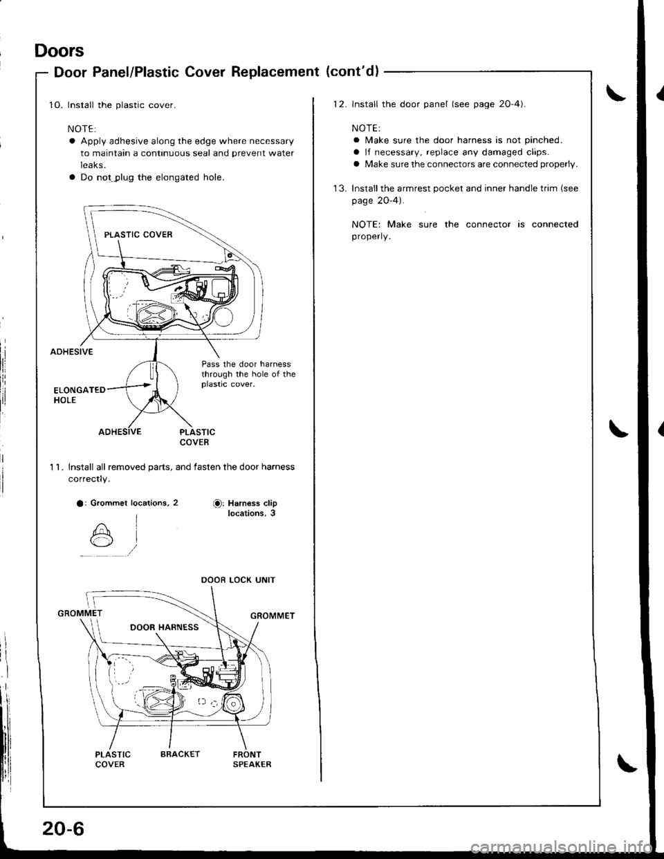
Door Panel/Plastic Cover Replacement (cont'dl
1O. Install the plastic cover.
NOTE:
a Apply adhesive along the edge where necessary
to maintain a continuous seal and prevent water
leaks.
a Do notJ)lug the elongated hole.
AOHESIVE
:
Pass the door harnessthrough the hole of theplastic cover.
PLASTICCOVEB
1 l� Install all removed oarts, and fasten the door harness
correctly.
a: Grommet locations, 2Or Harness cliplocations,3
GROMMET
PLASTICCOVERFRONTSPEAKER
DOOR LOCK UNIT
20-6
ARACKET
12. lnstall the door panel (see page 2O-4).
NOTE:
a lMake sure the door harness is not pinched.
a lf necessary, replace any damaged claps.
a Make sure the connectors are connected properly.
'13. Inslallthe armrest pocket and inner handle trim (see
page 2O-4).
NOTE: Make sure the connector is connected
properly.
Page 822 of 1681
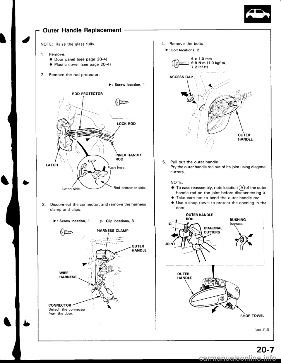
Outer Handle Replacement
NOTE: Raise the glass fully.
1. Remove:
a Door panel (see page 2O-4)
a Plastic cover (see page 20 4)
2. Remove the rod protector.
>: Screw localion, 1
INNER HANDLEROD
Push here.
Lalch srde.Rod protector side.
3. Disconnect the connector, and remove the harness
clamp and clips.
>: Screw location, 1
CONNECTORDetach the connector{rom the door.
8OD PFOTECTOR
4. Remove the bolts.
>: Bolt locations, 2
6 x 1.0 mm9.8 N.m {1.0 ksf m.1 .2 thl.tt)
5.Pull out the outer handle.
Pry the outer handle rod out of its joint using diagonal
cuners.
NOTE:
a To ease reassembly, note location @of the outer
handle rod on the joint before disconnecting it.a Take care not to bend the outer handle rod.
a Use a shop towel to protect the opening in the
door.
BUSHINGReplace.
h
SHOP TOWEL
(cont'd)
20-7
Page 823 of 1681
Doors
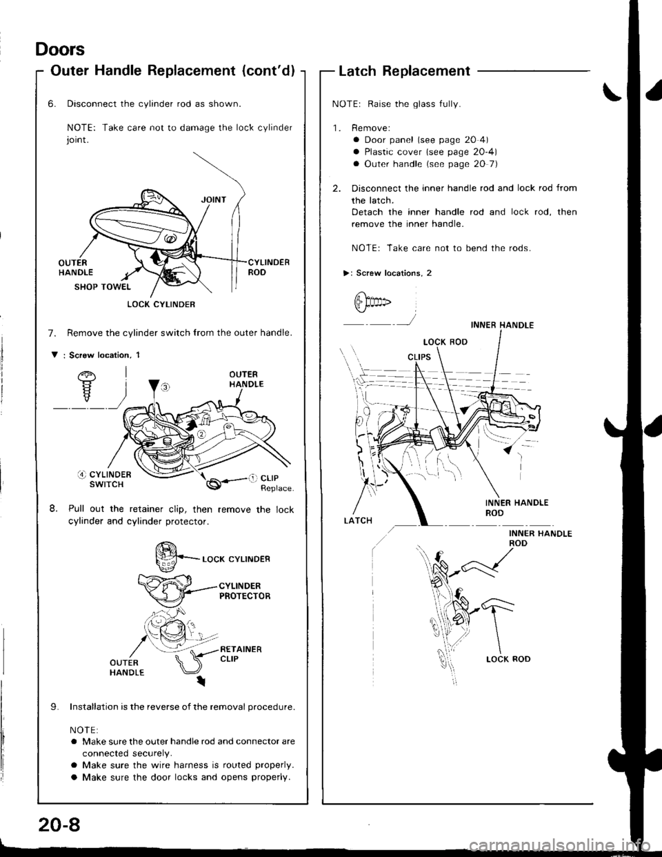
Outer Handle Replacement (cont'dlLatch Replacement
NOTEr Raise the glass fully.
'1. Remove:
a Door panel (see page 20 4)
a Plastic cover lsee page 20-4)
a Outer handle (see page 20 7)
2. Disconnect the inner handle rod and lock rod from
the latch.
Detach the inner handle rod and lock rod, then
remove the inner handle.
NOTE: Take care not to bend the rods.
>: Screw locations, 2
@t" ,
J
INNER HANDLEROD
INNER I{ANDLE
-1"'-
\
\LOCK ROD
)
INNER HANDLEROD
6.
8.
Disconnect the cylinder rod as shown.
NOTE: Take care not to damage the lock cylinder
joint.
OUTERHANDLECYLINDERROD
7.
V
SHOP TOWEL
Remove the cylinder switch lrom the outer handle.
: Scrsw location, 1
OUTERHANDLE
i4) cYLtNDERswtTcH
Pull out the retainer clip, then
cylinder and cylinder protector.
LOCK CYLINDER
li) clrPReplace
S*-.o"* .YLTNDER
CYLINDERPROTECTOR
RETAINERCLIP
Installation is the reverse of the removal procedure.
NOIE:
a Make sure the outer handle rod and connector are
connected securely.
a Make sure the wire harness is routed properly.
a Make sure the door locks and opens properly.
20-8
Page 824 of 1681
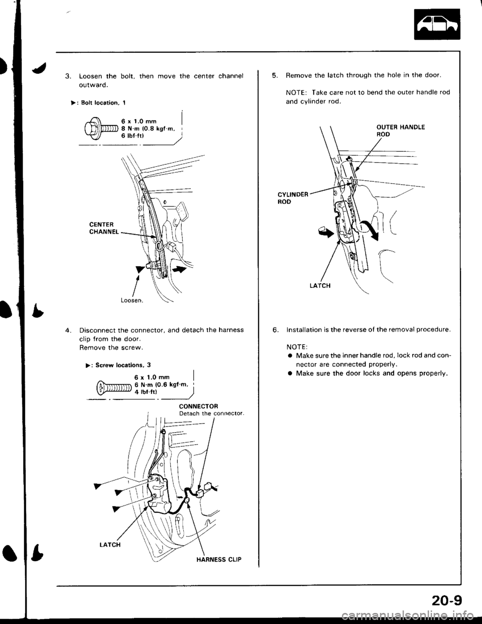
3. Loosen the bolt, then move the center channel
outward.
>: Bolt location, 1
6 x 1.0 mm8Nm {0.8kglm, I"*'l____)
CENTERCHANNEL
4.Disconnect the connector, and detach the harness
clip from the door.
Remove the screw,
>: Screw locations, 3
6x1.0mm IfiNrrlr
nr 6 N m (0.6 kgfm '
law iw.r,i )
CONNECTORDetach the connector.
5. Remove the latch through the hole in the door.
NOTE: Take care not to bend lhe outer handle rod
and cylinder rod.
CYLINDERROD
6. lnstallalion is the reverse of the removal procedure.
NOTEI
a Make sure the inner handle rod, lockrodandcon-
nector are connected properly.
a Make sure the door locks and opens properly.
20-9
Page 825 of 1681
Doors
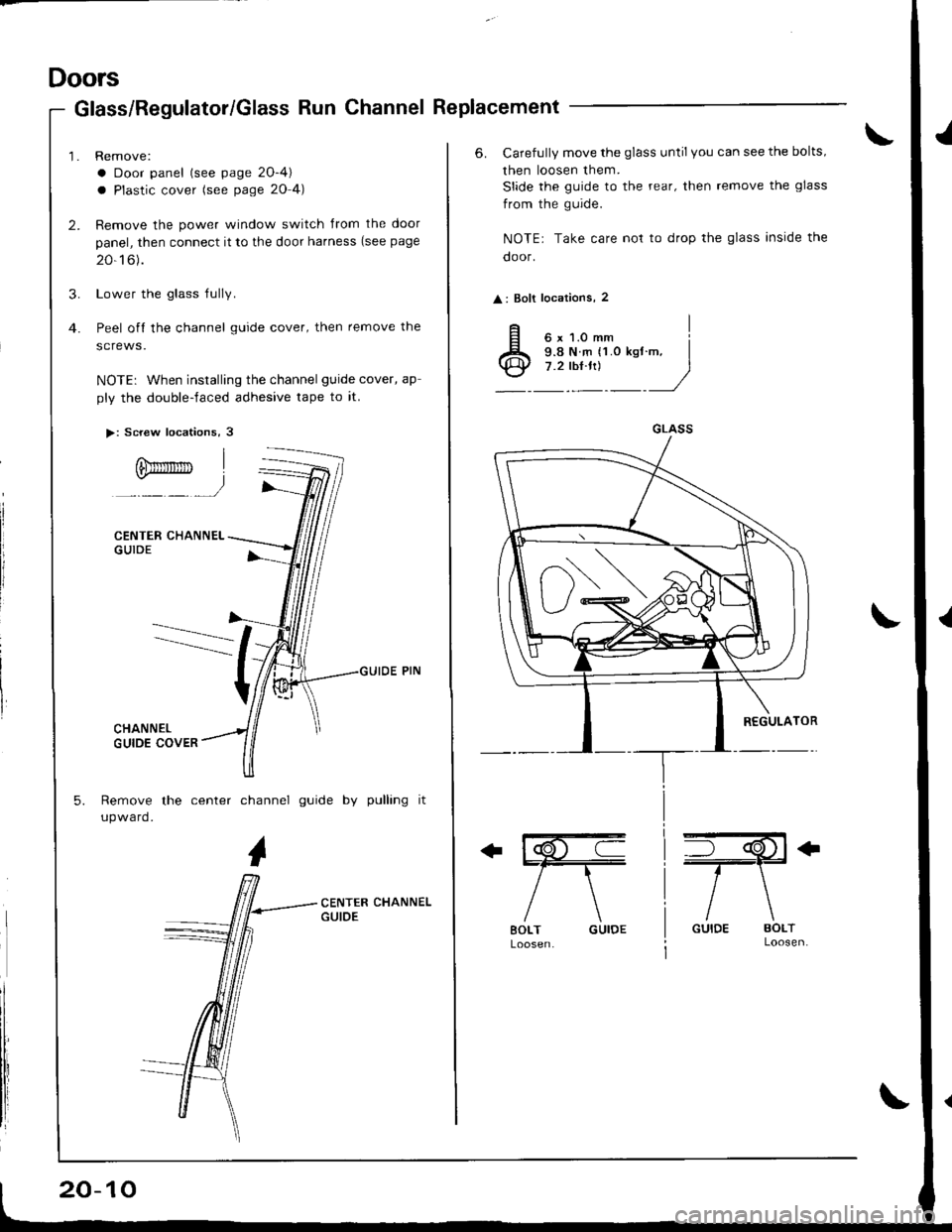
Glass/Regulator/Glass Run Channel Replacement
Remove:
a Door panel (see page 2O-4)
a Plastic cover (see page 20 4)
Remove the power window switch Jrom the door
panel, then connect it to the door harness (see page
20-16).
Lower the glass Iully.
Peel off the channel guide cover, then remove the
screws.
NOTE: When installing the channel guide cover, ap
ply the double-faced adhesive tape to it.
>: Screw locations, 3
CENTER CHANNELGUIDE
Remove the center channel guide by pulling it
upward.
Ofimnrrrn
20-10
6. Carefully move the glass until you can see the bolts,
then loosen them.
Slide the guide to the rear, then remove the glass
from the guide.
NOTE: Take care not to drop the glass inside the
door.
: Bolt locations, 2
ffi
/\
BOLT GUIDE
+il€+
/\
GUIDE BOLTLoosen.
GLASS
Page 826 of 1681
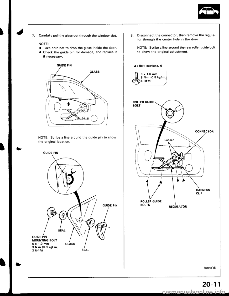
)7.Carefully pull the glass out through the window slot.
NOTE:
a Take care not to drop the glass inside the door.
a Check the guide pin for damage, and replace it
it necessary.
NOTEr Scribe a line around the guide pin to show
the original location.
GUIDE PIN
GUIDE PINMOUNTING BOLT6 r 1.0 mm3 N.m lO.3 kgl m,2 tbf.trl
GUIDE PIN
GUIDE PIN
SEAL
20-11
Disconnect the connector, then remove the regula-
tor through the center hole in the door.
NOTE: Scribe a line around the rear roller guide bolt
to show the original adiustment.
: Bolt locations, 6
6x1.0mmI N.m {0.8 kgf m6lbt.ftl
REGULATOR
(cont d)
Page 827 of 1681
Doors
Glass/Regulator/Glass Run Channel Replacement (cont'd)
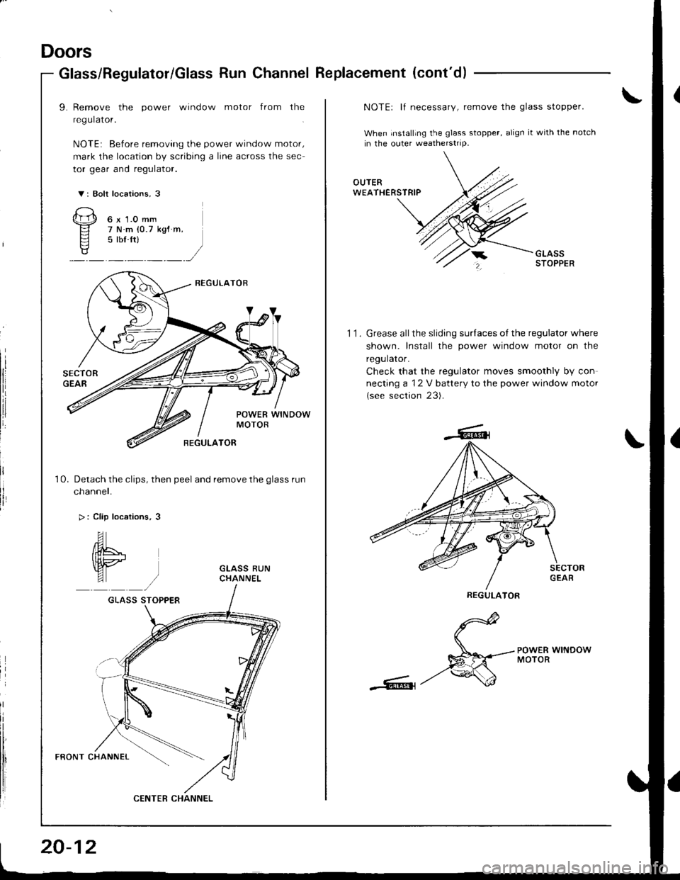
9. Remove the power window motor from the
regulator.
NOTE: Before removing the power window motor,
mark the location by scribing a line across the sec
tor gear and regulator.
V: Bolt locations, 3
Qp o"r.o--
El 7Nm(0.7ksf m.
Fl 5 lbf ftls?/:,/
Detach the clips, then peel and remove the glass run
cnanner.
> : Clip locations, 3
10.
GLASS STOPPER
FRONT CHANNEL
CENTEB CHANNEL
20-12
11.
NOTEr lf necessary, remove the glass stopper.
When installing the glass stopper, align it with the notch
in the outer weatherstrip.
Grease allthe sliding surlaces of the regulator where
shown. Install the power window motor on the
regulator.
Check that the regulator moves smoothly by con
necting a 12 V battery to the power window motor
(see section 23).
d
S*--.--;HERwrNDow
-Rt-/'
REGULATOR
Page 828 of 1681
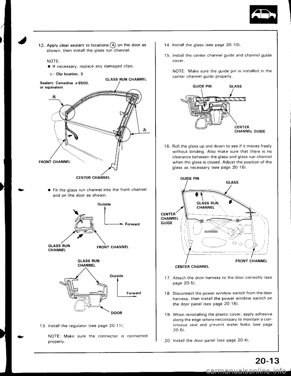
12. Apply clear sealant to locations @ on the door as
shown, then install the glass run channel.
NOTEI
a lf necessary, replace any damaged clips
>: Clip locarion, 3
Fit the glass run channel into the front channel
and on the door as shown.
Outside
CENTER CHANNEL
I
\.-, I
lffi, I/{ - ll r- Forward
rlc€\
/, \
nro.r(r" ,*), ""o**..CHANNEL
GLASS RUNCHANNEL
Outside
l---.*',
Install the regulator (see page 2O 11).
NOTE: Make sure the conneclor is connected
properly.
't 3.
20-13
14.
t3,
to.
Install the glass (see page 20 1Oi.
lnstall the center channel guide and channel guide
cover.
NOTE: Make sure the guide pin is installed in the
center channel guide properly.
GUIDE PINGLASS
CHANNEL GUIDE
Roll the glass up and down to see iI it moves freely
without binding. Also make sure that there is no
clearance between the glass and glass run channel
when the glass is closed. Adjust the position of the
glass as necessary lsee page 20 16).
GUIDE PINGLASS
CENTERCHANNELGUIOE
17.
18.
CENTEB CHANNEL
Attach the door harness to the door correctly (see
page 20 5).
Disconnect the power window switch from the door
harness, then install the power window switch on
the door panel (see page 20 16).
19. When reinstalling the plastic cover, applY adhesive
along the edge where neccessary to malntaln a con-
tinuous seal and prevent waler leaks (see page
20 6).
20. Install the door panel (see page 20 4).
GLASS RUNcxlrurutL \..
Er
FRONT CHANNEL
Page 829 of 1681
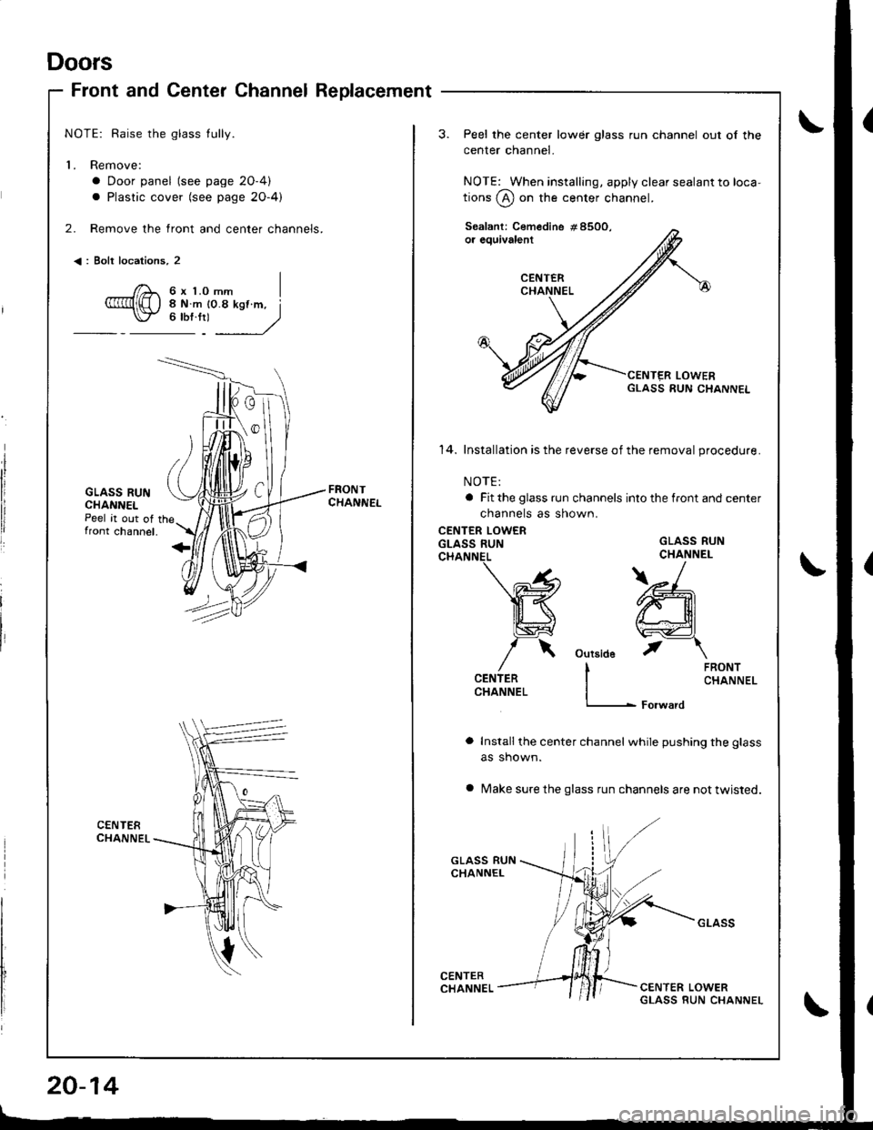
Doors
Front and Center ChannelReplacement
NOTE: Raise the glass tully.
L Remove:
a Door panel (see page 2O-4)
a Plastic cover (see page 2O-4)
2. Remove the front and center channels.
<: Bolt locations, 2
6xLomm I
GLASS RUNCHANNELPeel it out offront channel.
14. Installation is the reverse of the remova I procedure.
NOTE:
a Fit the glass run channels into the front and center
channels as shown.
CENTER LOWERGLASS RUN
Installthe center channel while pushing the glass
as shown.
Make sure the glass run channels are not twisted.
Peel the center lower glass run channel out of the
center channel.
NOTE: When installing, apply clear sealant to loca-
tions @ on the center channel.
GLASS RUNCHANNEL
)_
ffiil
\wdJ
outsid6 t-\
I FRONT
I CHANNEL
L- Forward
20-14
Page 830 of 1681
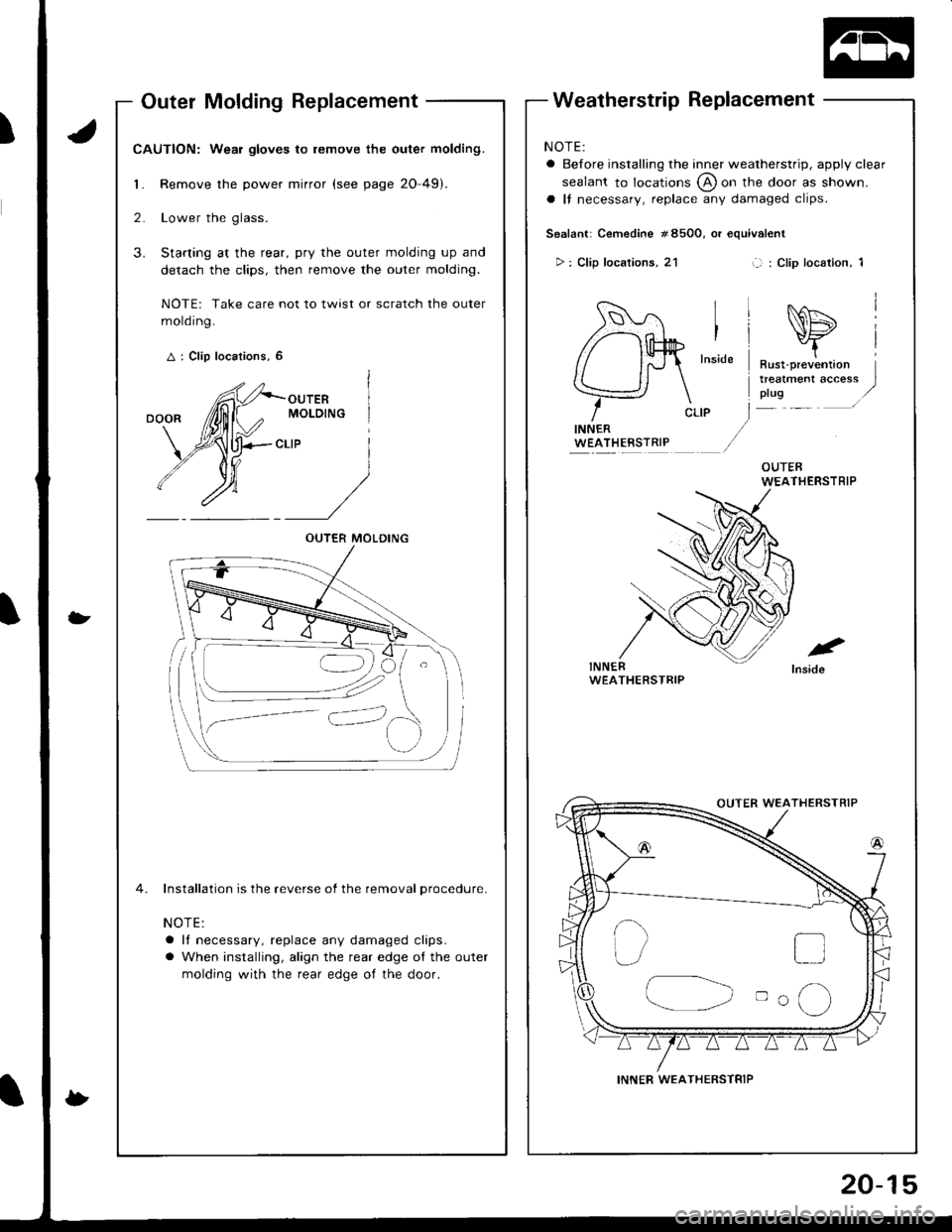
Outer Molding Replacement
CAUTION: Wear gloves to remove the outer molding.
1. Remove the power mirror (see page 20-49).
2. Lower the glass.
3. Starting at the rear, pry the outer molding up and
detach the clips, then remove the outer molding.
NOTE: Take care not to twist or scratch the outer
mold ing.
A : Clip locations, 6
OUTERMOLDING
CLIP
4. Installation is the reverse of the removal procedure.
NOTE:
a It necessary, replace any damaged clips.
a When installing, align the rear edge ot the outer
molding with the rear edge of the door.
OUTER MOLDING
i ---.-__
i--,'
NOTE:
a Before installing the inner weatherstrip, apply clear
sealant to locations @ on the door as shown.
a It necessary, replace any damaged clips.
Sealant: Cemedine #8500, or equivalent
>: Clip locations, 21L l : Clip location, 1
.e
Inside
INNERWEATHERSTRIP
WEATHERSTRIP
DD
oo(,)
INNER WEATHERSTRIP