HONDA INTEGRA 1998 4.G Workshop Manual
Manufacturer: HONDA, Model Year: 1998, Model line: INTEGRA, Model: HONDA INTEGRA 1998 4.GPages: 1681, PDF Size: 54.22 MB
Page 851 of 1681
Doors
Glass/Regulator/Center Glass Guide Replacement (cont'dl
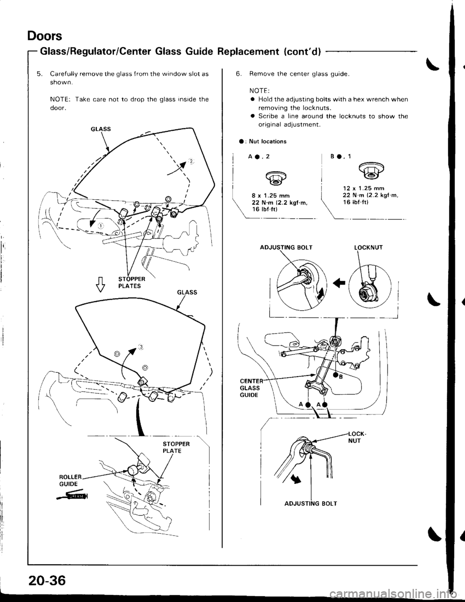
5. Carefully remove the glass Jrom the window slot as
shown.
NOTE: Take care not to drop the glass inside the
door.
x
ST
20-36
6. Remove the center glass guide.
NOTE:
a Hold the adiusting bolts with a hex wrench when
removing the locknuts.
o Scribe a line around the locknuts to show the
original adjustment.
a: Nut locations
aa.2B O, 1
12 x 1 .25 mm
v1'j-
LOCKNUT
,t^
(S)t
Y-l
[ ,"*.
22 N.m (2.2 ksf.m,
Vuloru,__
Page 852 of 1681
>: Bolt locations
l>A.4 >8.2
d|63il;o,ilIu'- *,@
i6pl-".
- 6rbr.ftr _!
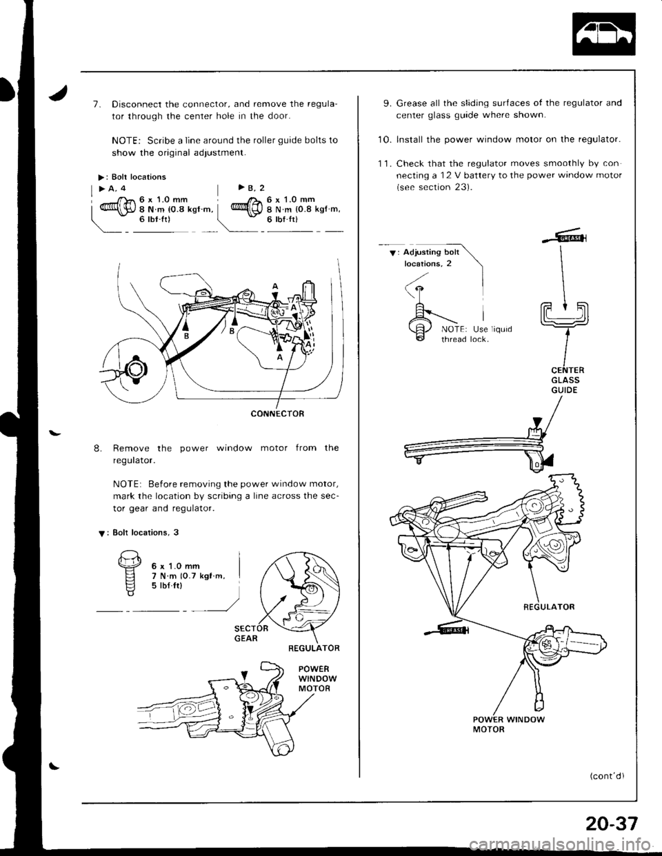
7. Disconnect the connector, and remove the regula'
tor through the cenler hole in the door.
NOTE: Scribe a line around the roller guide bolts to
show the original adlustment-
8. Remove the power window motor from the
regulator.
NOTE: Before removing the power window motor,
mark the location by scribing a line across the sec-
tor gear and regulator.
V: Bolt locations, 3
POWERwlNDowMOTOR
CONNECTOR
REGULATOR
9. Grease all the sliding surlaces of the regulator and
center glass guide where shown.
10. lnstall the power window motor on the regulator.
'l 1. Check that the regulator moves smoothly by con
necting a I2 V battery to the power window motor
(see section 23).
V: Adjusting bolt Ilocations,2 \l
\
\L
I ''II
A---- |
\H./ NOTE: Use liqurd@ thread lock.
fFtSlL!=-2
t
ICENTERGLASSGUIDE
MOTOR
(cont dI
20-37
Page 853 of 1681
Door
Glass/Regulator/CenterGlassGuide
Replacement (cont'd)
'12. Roll the glass up and down to see if it moves freely
without binding. Also make sure that there is no
clearance between the glass and weatherstrip when
the glass is closed. Adjust the position of the glass
as necessary (see page 20 40;.
Attach the door harness to the door correctly
page 2O-33).
Disconnect the power window switch from the
harness.
(see
14.door
When reinstalling the plastic cover, apply adhesive
along the edge where neccessary to maintain a con-
tinuous seal and prevent water leaks (see page
20 33).
16. lnstall the door panel {see page 2O-32).
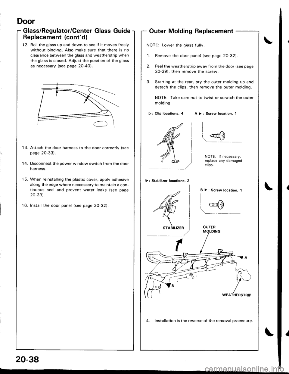
Outer Molding Replacement
\NOTE: Lower the glass fully.
'1. Remove the door panel (see page 2O-32).
2. Peelthe weatherstrip away from the door (see page
2O-39i, then remove the screw.
3. Starting at the rear, pry the outer molding up and
detach the clips, then remove the outer molding.
NOTE: Take care not to twist or scratch the outer
molding.
>i Clip locations, 4 A > : Screw location, 1
>: Stabilizo. locstions, 2
.0s{0
\�-
NOTEi lf necessary,replace any damagedclrps.
I ): Screw location. 1
_,f"\tjru{ 1i)
\__ -
OUTER
4. lnstallation is the reverse of the removal Drocedure.
20-38
l-
1
Page 854 of 1681
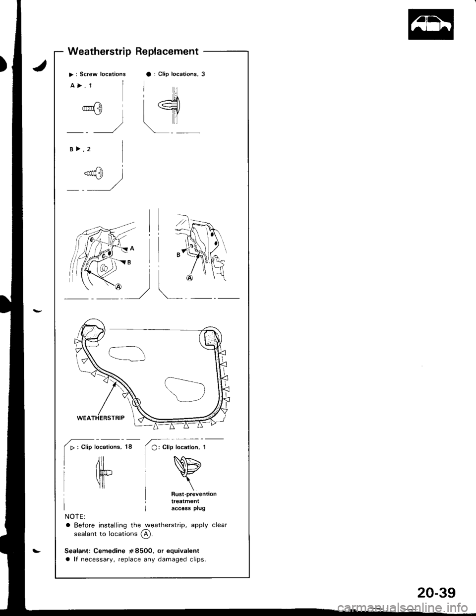
Weatherstrip Replacement
>: Scr€w locationsa : Clip locations, 3
iI
L.:5\
l-fl
!l
a>,1
B>,2
.rf@
NOTE:
a Before installing the weatherstrip, apply clear
sealant to locations @.
Sealant: Cemedine #8500. or equivalent
a It necessary, replace any damaged clips.
*/]"l
tA
;, I
l
IW
[^_]
locations.
/il
Itr"r tl
18
20-39
Page 855 of 1681
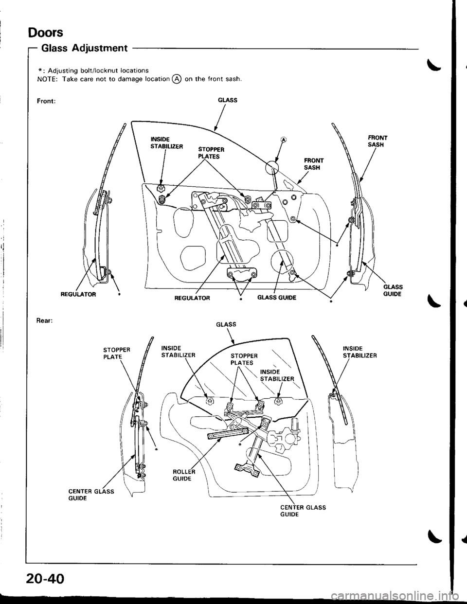
Doors
Glass Adjustment
\*: Adjusting bolt/locknut locations
NOTE: Take care not to damage location @ on the front sash.
\
INSIDESTABILIZEB
\
20-40
r---
GLASS
GLASS GUIDE
GLASS
\
,"a,o'a t \STABILIZER
\../ \
Page 856 of 1681
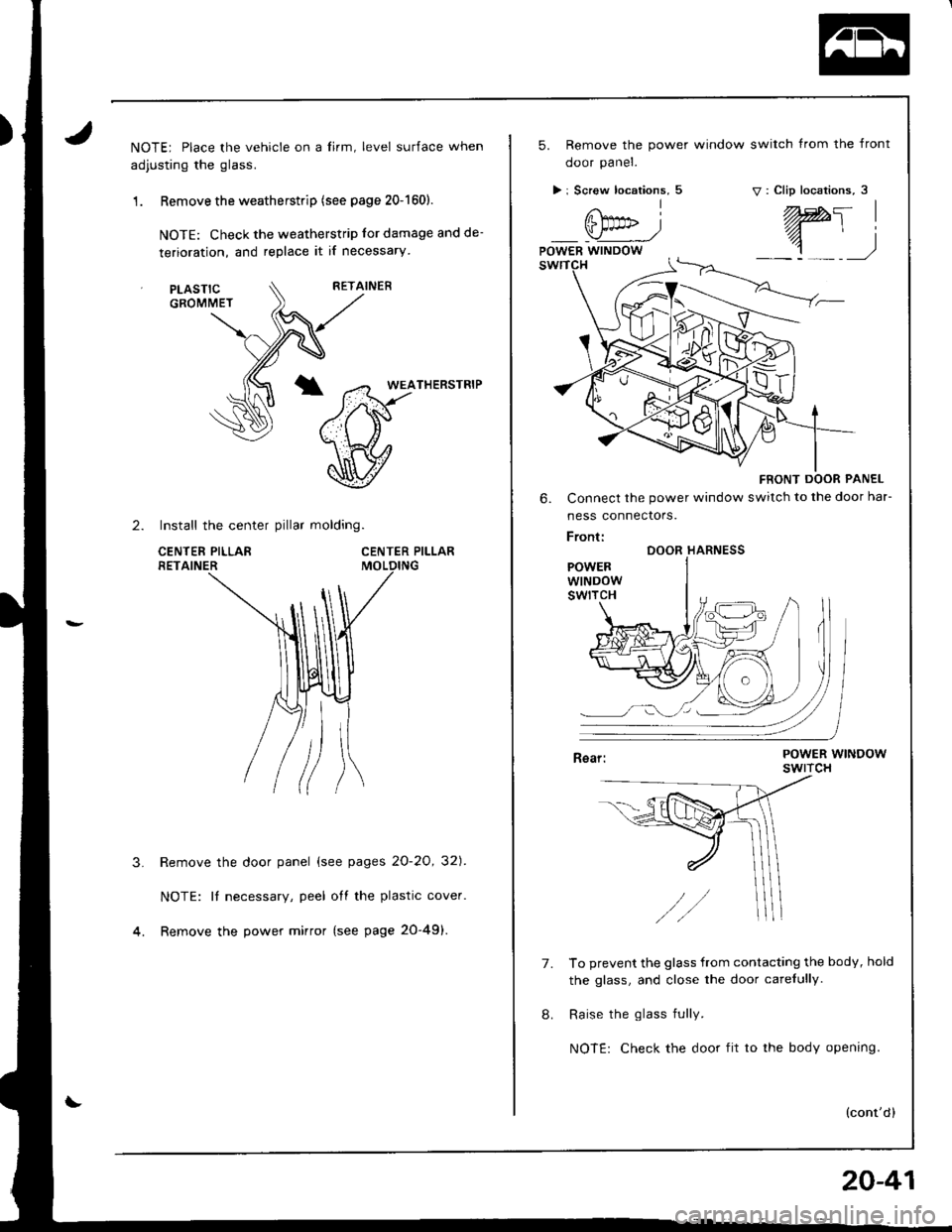
NOTE; Place the vehicle on a lirm, level surface when
adjusting the glass.
1 . Remove the weatherstrip (see page 20-1601.
NOTE: Check the weatherstrip lor damage and de-
terioration, and replace it if necessary
RETAINER
*T5FrHERsrR'P
\v
CENTER PILLAR
2. Install the center pillar molding.
CENTEF PILLARRETAINER
PLASTICGROMMET
3.Remove the door panel (see pages 2O-2O, 32]'.
NOTE: It necessary, peel off the plastic cover.
Remove the power mirror (see page 20-49).
5. Remove the power window switch from the front
ooor paner.
> i Screw locations, 5v: Clip locations, 3
FRONT DOOR PANEL
6. Connect the power window switch to the door har-
ness connectors.
Front:DOOR HARNESS
POWERWINDOWswtrcH
7.To prevent the glass from contacting the body, hold
the glass, and close the door carefully.
Raise the glass fully.
NOTE: Check the door fit to the body opening.
(cont'd)
20-41
Page 857 of 1681
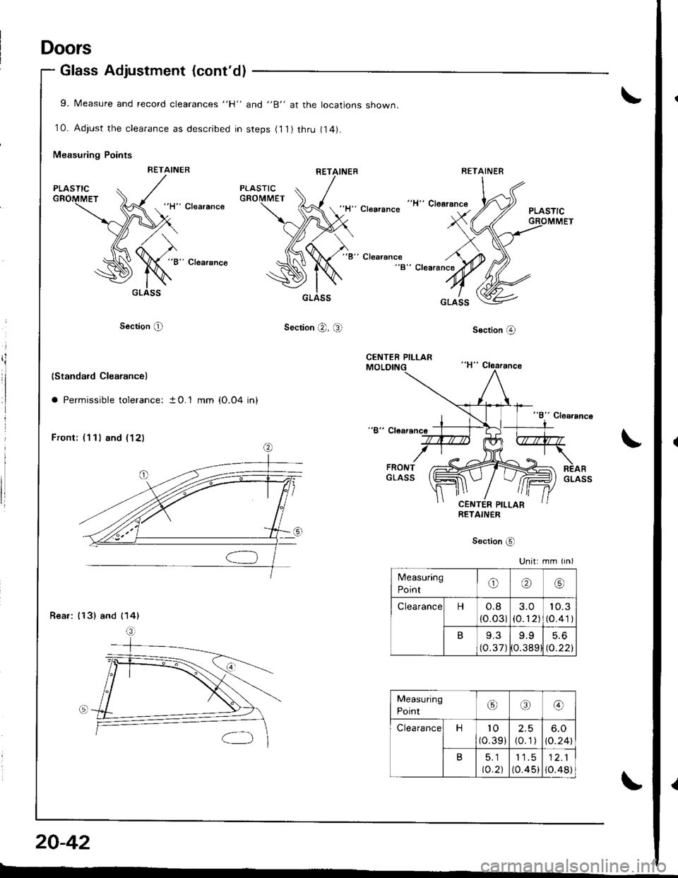
Doors
Glass Adjustment (cont'dl
9. Measure and record clearances "H" and "B" at the locations shown.
10. Adjust the clearance as described in steps (11) thru r4).
Measuring Points
RETAINER
"ll" Clearance'Clearance
"B" Clearsnce"B" Clearance
Section O
GLASS
Section @, Ql
RETAINEBRETAINER
20-42
"B" Clearance
"H" Clearance
socrion @
GLASSGLASS
(Standard Clearance)
a Permissible tolerance: t 0.1 mm (O.04 in)
Front: (111 and ( 121\
Rear: (13) and (141
Unit: mm iin)
Measuring
Pointo(r\\9
Clearancet-l0.8(o.03)3.O
1o.12)
10.3
(o.41)
B9.3(0.37 )
9.9
0.389
5.6
to.22l
Measuring
Point,6€)
Clearancen'to
(0.39 )
2.5
10.1)
6.O
\o.241
B5_l
to.2J
11.5(o.45)12.1
{o.48)
L---
{
Page 858 of 1681
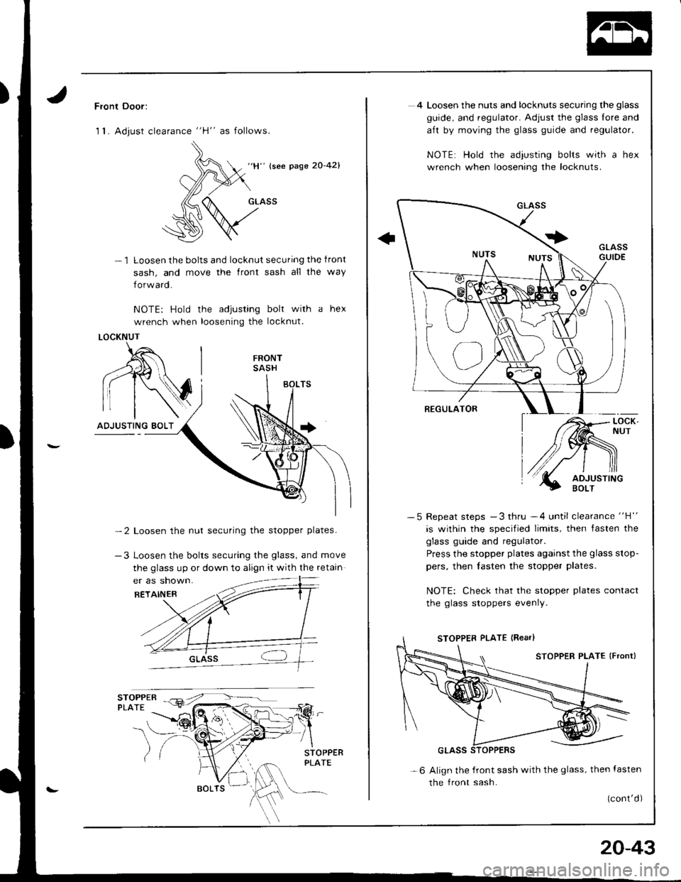
Front Door:
1 1. Adjust clearance "H" as follows.
-1
" {see page 20-42}
Loosen the bolts and locknut securing the front
sash, and move the front sash all the way
forw ard.
NOTE: Hold the adjusting bolt with a hex
wrench when loosening the locknut.
-2 Loosen the nut securing the stopper plates.
-3 Loosen the bolts securing the glass, and move
the glass up or down to align it with the retain
STOPPER €-r7 -\---
PLATE lErt-:<'7--
LOCKNUT
4 Loosen the nuts and locknuts securing the glass
guide, and regulator. Adjust the glass lore and
aft by moving the glass guide and regulator.
NOTE: Hold rhe adjusting bolts with a hex
wrench when loosening the locknuts.
-5 Repeat steps -3 thru -4 until clearance "H"
is within the specified limits, then tasten the
glass guide and regulator.
Press the stopper plates against the glass stop-
pers, then fasten the stopper plates.
NOTE: Check that the stopper plates contact
the glass stoppers evenly.
- 6 Align the front sash with the glass, then lasten
the front sash.
(cont'd)
20-43
Page 859 of 1681
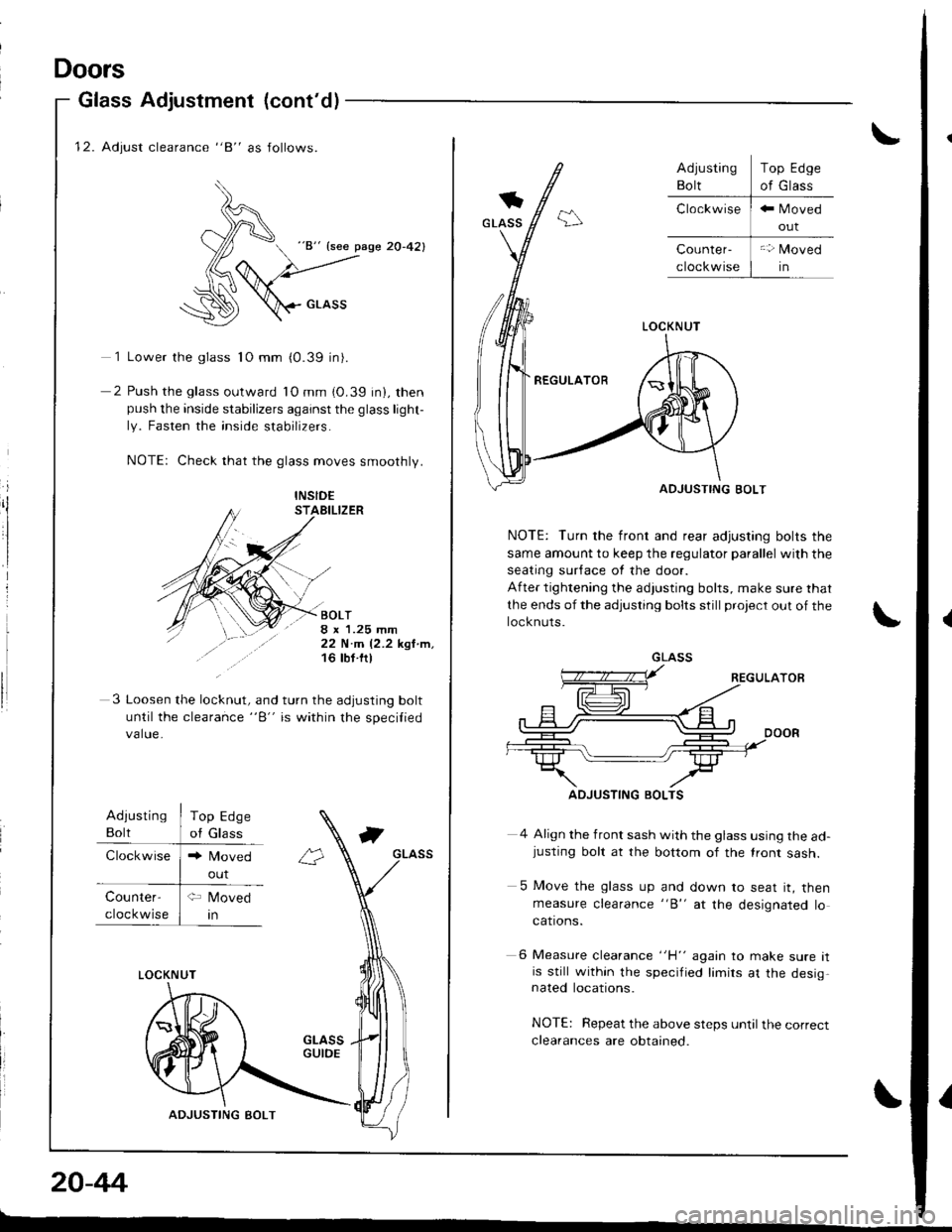
12. Adjust clearance "8" as follows.
)^
d "8" {see pase 20-42}
(6
:\D \crnss
1 Lower the glass 1O mm (0.39 in).
2 Push the glass outward lO mm (0.39 in), thenpush the inside stabilizers against the glass light-
ly. Fasten the inside stabilizers.
NOTE: Check that the glass moves smoothly.
i
ilINSID€STAEILIZER
BOLT8 x 1.25 mm22 N.m 12.2 kgl.m,16 tbt ftl
3 Loosen the lo"knrt, "nd turn the adjusting bolt
until the clearance "B" is within the specilied
value.
Adiusting
Bolt
Clockwise
Top Edge
of Glass
Counter-
cloc kwise
LOCKNUT
ADJUSTING BOLT
20-44
Doors
Glass Adjustment (cont'd)
out
\
LOCKNUT
REGULATOR
ADJUSTING BOLT
NOTE: Turn the front and rear adjusting bolts the
same amount to keep the regulator parallel with the
seating sur{ace ot the door.
After tightening the adjusting bolts, make sure that
the ends of the adjusting bolts still project out of the
locknuts.
4 Align the front sash with the glass using the ad-justing bolt at the bottom of the lront sash.
5 Move the glass up and down to seat it, thenmeasure clearance "B" at the designated locations.
6 Measure clearance "H" again to make sure itis still within the specified limirs at the desig,nated locations.
NOTE: Repeat the above steps until the correct
clearances are obtained.
Top Edge
of Glass
GLASS
ADJUSTING BOLTS
I
Page 860 of 1681
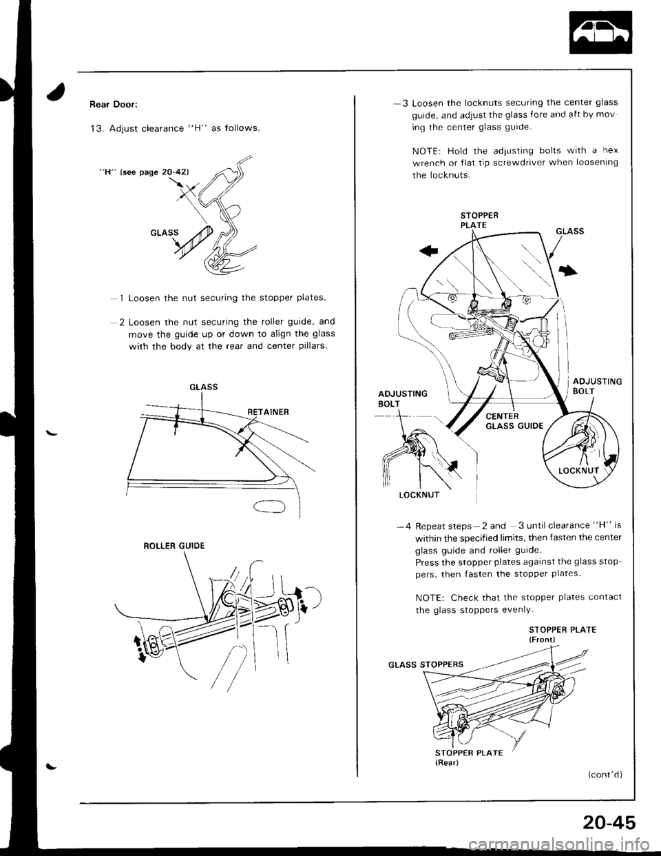
Rear Door:
13. Adjust clearance "H" as lollows.
"H" {see page 20-42)
1 Loosen the nut securing the stopper plates.
2 Loosen the nut securing the roller guide, and
move the guide up or down to align the glass
with the body at the rear and center pillars.
GLASS
ROLLER GUIDE
LOCKNUT
3 Loosen the locknuts securing the center glass
guide, and adiust the glass Jore and aft by mov
ing the center glass gurde.
NOTE| Hold the adiLrsting bolts with a hex
wrench or flat tip screwdriver when loosening
the locknuts.
STOPPERPLATE
-4 Repeat steps 2 and 3 until clearance "H" is
within the specified limits, then fasten the center
glass guide and roller guide.
Press the stopper plates agarnst the glass stop
pers, then fasten the stopper plates.
NOTE: Check that the stopper plates contact
the glass stoppers evenlY.
STOPPEB PLATE{Front)
(cont'd )
20-45